Significance
This paper covers aspects of the dynamics of fluids that are of central importance for (i) the origin of planetary and astrophysical magnetism, and (ii) the determination of stable magnetic field configurations used in thermonuclear fusion reactors like the tokamak. The technique of magnetic relaxation also has implications for the theory of tight knots, an emerging field of research with applications in polymer physics and molecular biology. The final section on slow viscous flows has relevance for the design of micro- and nanofluid devices, and for the understanding of mixing processes in chemical engineering and in geophysics.
Keywords: vortex dynamics, turbulent dynamo, energy of knots, corner eddies, chaos
Abstract
Helicity is, like energy, a quadratic invariant of the Euler equations of ideal fluid flow, although, unlike energy, it is not sign definite. In physical terms, it represents the degree of linkage of the vortex lines of a flow, conserved when conditions are such that these vortex lines are frozen in the fluid. Some basic properties of helicity are reviewed, with particular reference to (i) its crucial role in the dynamo excitation of magnetic fields in cosmic systems; (ii) its bearing on the existence of Euler flows of arbitrarily complex streamline topology; (iii) the constraining role of the analogous magnetic helicity in the determination of stable knotted minimum-energy magnetostatic structures; and (iv) its role in depleting nonlinearity in the Navier-Stokes equations, with implications for the coherent structures and energy cascade of turbulence. In a final section, some singular phenomena in low Reynolds number flows are briefly described.
This inaugural article, although long delayed, is now fortuitously quite timely for various reasons. First, helicity in fluid dynamics is a measure of the knottedness and/or linkage of the vortex lines of a flow (1), invariant under ideal-fluid Euler evolution. Knotted vortices were first conceived by Lord Kelvin (then Sir William Thomson) in 1868 (2), but have only recently been unambiguously observed: a vortex in the form of a trefoil knot has been generated in a remarkable experiment by Kleckner and Irvine (3) by means of an ingenious technique that can in principle be adapted to generate vortices of arbitrarily linked or knotted form. The possible existence of knotted vortices is therefore no longer a matter of mere speculation!
Second, helicity has long been known to be of crucial importance in turbulent dynamo theory—the theory of the spontaneous growth of a magnetic field in a conducting fluid in turbulent motion. The associated chirality of the flow is responsible for the α-effect (4), which is a crucial ingredient of the dynamo process in stars and planets. The von Karman sodium (VKS) experiment (5) developed in France over the last decade has at last provided convincing evidence for a turbulent dynamo mechanism that undoubtedly involves this α-effect in conjunction with differential rotation and strong diffusive processes.
Third, the process of magnetic relaxation of a knotted magnetic flux tube in a perfectly conducting fluid under the topological constraint of invariant helicity leads in a natural physical way to the concept of the energy spectrum of knots and links (6). The minimum energy configurations obtained by this procedure are, with certain qualifications, essentially the same as the ideal or tight knot configurations introduced by Katritch et al. (7) which minimize the length-to-diameter ratio of knotted tubes. Tight knots have found wide application in polymer physics and molecular biology, as discussed in recent workshops of the Isaac Newton Institute for Mathematical Sciences (8, 9), and huge progress has been made in determining all tight configurations for links and knots up to 9 and 10 crossings, respectively (10). In particle physics, a striking correlation has been noted between the knot/link energies and the mass/energies of glueballs in the quark–gluon plasma (11); the subject has perhaps come full circle since the time of Kelvin!
The time is therefore ripe to review some of the salient features of these and related phenomena in which helicity plays a central role, and I take this welcome opportunity to do so. I include also, at the suggestion of a referee of this article, a section on certain structures that can arise in flows that are dominated by viscosity, and that nevertheless exhibit structures of nontrivial topology.
Historical Background
Consider the flow of an ideal barotropic fluid, i.e., one whose viscosity is negligible and in which the pressure p is functionally related to the density ρ, i.e.,  . Let
. Let  be the velocity field in such a fluid, and let
  be the corresponding vorticity field. In one of the great classic papers of fluid mechanics, Helmholtz (12) proved that if such a fluid flows under the influence of conservative body forces, then the vortex lines of the flow are transported with the fluid, with conservation of the flux of vorticity across any Lagrangian surface element. This property (often described as “frozen field”) is encapsulated in the vorticity equation
Ten years later, Kelvin (2) recognized that any links or knots in vortex lines should, in these circumstances, persist, at least for so long as the flow field remains differentiable. (This persistence is by no means guaranteed for all time: the possible development of singularities of vorticity within a finite time starting from smooth initial conditions is still an open problem of great current challenge.) It was this realization that led Kelvin to propose his bold but ill-fated vortex theory of atoms, in which he sought to identify the stable elements, hydrogen, helium, lithium, and so on, with a succession of knots and links of increasing complexity, and to explain the spectral properties of the elements in terms of the frequencies of vibration of these elemental knotted and linked structures. Unfortunately for Kelvin, his subsequent extensive investigations (2) revealed that even quite elementary vortical flows in ideal or nearly ideal fluids are unstable. The instability of any rectilinear shear flow whose velocity profile has a point of inflection is prototypical; this indeed may be seen as one of the root causes of the phenomenon of turbulence.
For a localized vorticity distribution  in a fluid of infinite extent, the helicity of the associated flow is defined by
 |
the integral being over all space. This integral is, like energy, an invariant of the Euler equations of ideal fluid flow, and its physical interpretation is that it provides a measure of the degree of knottedness and/or linkage of the vortex lines of the flow (1). It is also a measure of the lack of mirror symmetry of the flow (see below), which is why it is appropriate to denote it with the non–mirror-symmetric script character ℋ.
That this result lay hidden for nearly a century following the discoveries of Helmholtz and Kelvin is quite remarkable. I came on the result from seeking to interpret an analogous result of Woltjer (13) in the context of magnetohydrodynamics (MHD). Let  be a localized magnetic field in a perfectly conducting fluid, with vector potential
  , i.e.,
  . The evolution equation for B is
which bears immediate comparison with [1]. Indeed, by analogy with the result of Helmholtz, it can be easily deduced from [3] that the magnetic lines of force (the B lines) are similarly frozen in the fluid (14). Woltjer (13) showed that the integral that we now know as “magnetic helicity,” namely
 |
is an invariant of Eq. 3. It is also gauge invariant. It was through struggling to understand the physical significance of this invariant that I stumbled on its topological interpretation: it is (as now seems perfectly obvious) simply a measure of the degree of linkage of the B-lines which is conserved by virtue of the frozen-in property. It was then a small step to exploit the analogy between [1] and [3], and to infer that ℋ must be likewise conserved whenever conditions are such that the vortex lines are frozen in the flow. These conditions are threefold: (i) the fluid must be inviscid, (ii) the flow must be either barotropic or incompressible, and (iii) the forces acting upon the fluid must be conservative.
I published my 1969 paper (1) in ignorance of two prior publications. In 1961, Betchov (15) had recognized the possible significance of the mean helicity  in turbulent flow (and had indeed used this terminology), but he gave no hint of the all-important invariance of ℋ under Euler evolution. In the same year, coincidentally, Moreau (16) did discover the invariance of ℋ, and deserves great credit for this. My independent discovery came eight years later, but I went somewhat further in recognizing its relationship with the magnetic helicity invariant (of the ideal MHD equations) and with the cross-helicity invariant of ideal MHD,
 |
which similarly admits topological interpretation associated with the conserved flux of vorticity across any open orientable surface bounded by a closed B-line. I also gave examples of various steady solutions of the Euler equations having nonzero helicity.
It should be noted that, since  is the scalar product of a pure vector u and a pseudovector ω, helicity is a pseudoscalar, i.e., it changes sign under a change from a right- to a left-handed frame of reference. It is a measure of the chirality, or handedness, or lack of mirror symmetry of the flow. The streamlines of the flow are locally like helices, and if the frame of reference is right-handed, these helices are right- or left-handed according as
  .
.
Knotted Vortex Tubes
For two linked but unknotted vortex tubes of circulations  and
and  inside each of which the vortex lines are unlinked closed curves, it is not difficult to show that the helicity is
  , where n is the Gauss linking number of the two tubes, and the sign + or − is chosen according to whether the linkage is right- or left-handed.
For a single knotted tube of circulation Γ whose axis is in the form of a knot K, say, the situation is more complicated. We may suppose that the vortex lines within such a tube are all closed curves lying on a family of tori, each torus being of course knotted in the form of the same knot K. The innermost member of this family is the axis C of the tube; let s represent arclength measured along C from some point of this curve. Consider the ribbon  whose boundaries are the curve C and any other vortex line in the tube. We suppose that the tube is uniformly twisted, in the sense that each such ribbon has the same integer number
  of turns relative to the the Frenet triad of unit vectors
  on C;
on C;  , which may be described as the internal twist of the tube, is well defined only if there are no inflection points on C, i.e., no points where the curvature
  vanishes.
The writhe  of C is defined by
 |
an integral that is convergent despite the dangerous appearance of the denominator. Further, if  is the torsion of C, then the twist
  of the ribbon
  is given by
where
 |
It is known (17–19) that, under continuous deformations of the ribbon,  ; also (20) that the helicity of the vortex tube is given by
a formula that provides a very natural bridge between the invariant ℋ of the Euler equations and the equally well-established invariant  of differential geometry.
Under continuous deformation of the tube,  and
and  vary continuously, subject to
  . However, if the curve C passes through an inflectional configuration at time
  say, i.e., if
  at some point
  at this instant, then the Frenet triad flips through an angle π about the tangent vector t at this point and instant; the net effect, as shown in ref. 20, is that
  jumps by
  and
and  has a compensating jump of
  . In this way, writhe can be converted to internal twist, as in the process illustrated schematically in Fig. 1. At a certain point during the process illustrated, the central curve C passes through an inflectional configuration, enabling the unit jump in internal twist.
Fig. 1.
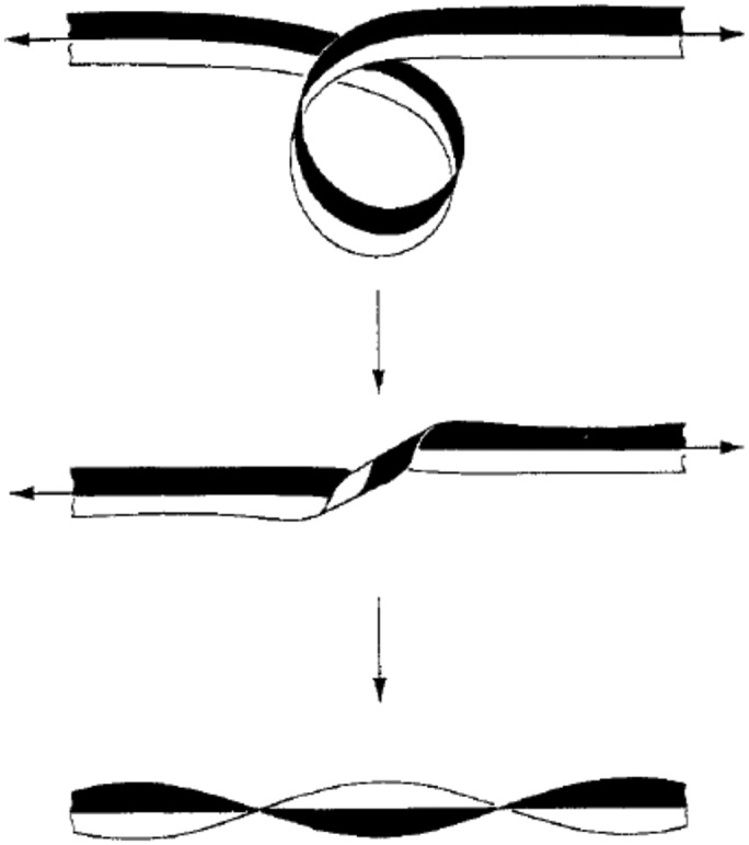
Conversion of writhe to internal twist; during this deformation,  decreases continuously from 1 to 0, and
  increases continuously from 0 to 1; the central curve passes at some instant through an inflectional configuration, and at this instant
  decreases by unity and
  increases from 0 to 1. [Reproduced with permission from ref. 20 (Copyright 1992, The Royal Society).]
For many years, the possible existence of knotted vortices has been a matter of speculation. For, just as (barring singularities) a knotted vortex retains its knotted form in perpetuity in an ideal fluid, so it is impossible to create a knotted vortex from an initially unknotted vorticity distribution in an incompressible fluid without the agency of viscosity, which is in principle capable of inducing the type of vortex reconnection necessarily associated with the change of vortex topology. Such speculation has however been laid to rest through the experiment of Kleckner and Irvine (3), who have succeeded in generating a vortex in the form of a trefoil knot. They have done this by skillful fabrication (using a 3D printer) of a knotted airfoil which can be jerked into motion in a tank of water, shedding a vortex from its sharp trefoil-knotted trailing edge. This vortex has to propagate across the airfoil, and this is achieved again by appropriate airfoil design, the result being that the knotted vortex can separate from the generating mechanism, and continue to evolve freely as it propagates downstream. The water is seeded with small bubbles which are attracted to the core of the vortex where the pressure is minimal, making this core clearly visible.
As might have been expected (except perhaps by Kelvin during his vortex atom period!) the trefoil vortex is unstable, and initially well-separated parts of the tube come into close coincidence in a time of order  , where l is, say, the mean radius of curvature of the vortex when initially formed, and Γ its circulation. As explained by Kleckner and Irvine, this comes about because the inner turns of the trefoil tend to propagate more rapidly that the outer turns where the curvature is less. Because of the threefold symmetry of the original trefoil, this actually produces three pairs of nearly antiparallel but slightly skewed strands of vorticity, each pair being stretched by the induced velocity gradient. It appears that reconnection occurs at these three locations, the trefoil then converting into two unlinked vortex rings. The initial writhe helicity is destroyed during this reconnection process; whether it reappears as twist helicity in either or both emerging rings is still a matter of controversy.
Magnetic Relaxation
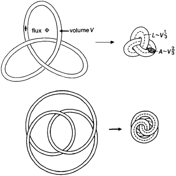
The concept of stable (as opposed to unstable) knotted structures is on firmer ground in the context of magnetic flux tubes. Consider such a tube in the form of a knot K carrying magnetic flux Φ. Consider the thought experiment (conceived by Zel’dovich according to Arnol’d) (21) in which such a tube is released in an incompressible, perfectly conducting but viscous fluid initially at rest. The Lorentz force manifests itself as Maxwell tension in the tube, which in general causes its length L to decrease. As it does so, it evolves according to [3], and its topology and the flux Φ are therefore conserved. The volume V of the tube is also conserved because the fluid is incompressible, and so the average cross-sectional area  must increase as L decreases.
As the contraction proceeds, the magnetic energy M is converted to kinetic energy which is dissipated by viscosity. However, M has a positive lower bound determined by the helicity  (21):
(21):
where  is a constant (with the dimensions of length) proportional to the scale of the initial field distribution. The existence of a strictly positive lower bound has been proved for any field of nontrivial topology, even if the helicity is zero (22). This is essentially because the shrinking of any closed field line to a point necessarily involves infinite stretching of any trapped field, whether that field has zero net flux or not. The Whitehead link and the Borromean rings are frequently cited in this context (23).
For any nontrivial topology, the magnetic energy must therefore ultimately attain a nonzero minimum, given on dimensional grounds (6) by
Here,  is a dimensionless function of the dimensionless helicity parameter h. This minimum-energy function characterizes the knot K, different knots having different minimum-energy functions. The minimum-energy state is attained only when viscous dissipation ceases, i.e., when the fluid again comes to rest; hence this is a magnetostatic equilibrium described by a balance between Lorentz force and pressure gradient:
Remarkably therefore, with the reservations noted below, we may assert that, for arbitrary initial topology of a field B that is localized and of finite energy, there exists a minimum energy magnetostatic state having the same prescribed topology. In particular, for a flux tube in the form of an arbitrary knot K, there exists such a state, which is evidently stable (being of minimum energy), the fluid being assumed perfectly conducting.
Here, three notes of caution are needed. First, it seems inevitable that the topological constraint bites only when the knot tightens to such an extent that it really makes contact with itself; this process is illustrated for the trefoil knot in Fig. 2. In the tightened state, the field obviously exhibits tangential discontinuities (i.e., current sheets) over any area where this contact occurs. The mapping that takes the initial field to the final relaxed field is not then a homeomorphism; all one can say is that the relaxed field is topologically accessible from the initial field, being obtained from it by the action of a smooth velocity field (isotopy) that dissipates a finite amount of energy during the whole relaxation process (24).
Fig. 2.
Relaxation of the trefoil knot to a tight minimum-energy state; two representations of the knot are shown ( and
and  , upper and lower, respectively) indicating the existence of two distinct minimum-energy states. [Reproduced with permission from ref. 6 (Copyright 1990, Macmillan Magazines Ltd.).]
Second, again as indicated in Fig. 2, for a given knot K and a given value of the twist parameter h, more than one tight state may be possible, each being a local minimum with respect to frozen-field perturbations. We may therefore in general envisage a spectrum of such states, which may be ordered in increasing energy, the ground state being that with lowest energy.
Third, if h is large, then the strong component of field in planes perpendicular to C tends to contract the cross-section, rather than allowing it to expand; however the tube is then subject to kink instability introducing writhe at the expense of internal twist. Even the unknot is subject to this instability and may be expected to be highly contorted in its minimum energy state when h is large.
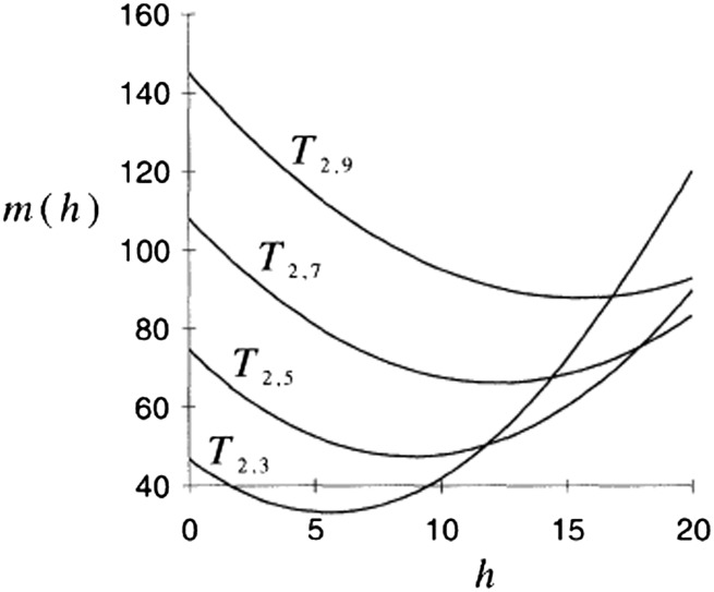
The function  has been computed (Fig. 3) for a set of right-handed torus knots (25) under the simplifying assumptions that (i) the tube cross-section is circular and uniform along its length and (ii) no kink instability occurs. In each case the curve has a minimum for a nonzero value of h, reflecting the fact that these knots are chiral; and the minimum
  increases with n, i.e., with increasing knot complexity, as might be expected. If the assumption of uniform circular cross-section is removed, these minimum energy curves will all be displaced downward presumably by a fairly small amount. Kink instability will lower them further when h is large, by an amount as yet undetermined.
Fig. 3.
Minimum-energy curves  for torus knots
  for
for  . [Reproduced with permission from ref. 25 (Copyright 1995, The Royal Society).]
Helicity and the Dynamo Problem
Nowhere is helicity more important than in the context of the spontaneous generation of magnetic fields in conducting fluids in turbulent motion, i.e., MHD dynamo action. A dramatic breakthrough took place in 1966 through the work of the Potsdam group, Steenbeck et al. (4), who discovered what is generally known as the “α-effect,” namely the appearance of a mean current parallel to a mean magnetic field, where the mean is an average over scales large compared with the scale of the energy-containing eddies of the turbulence. The essential mechanism is indicated schematically in Fig. 4: a rising twisting blob of fluid [evidently a localized velocity field characterized by nonzero helicity—a “cyclonic event” in Parker’s much earlier terminology(26)] distorts and twists an ambient magnetic field so that a current, here antiparallel to the field, is apparently generated. One must imagine such events distributed randomly in space and in time, and use appropriate averaging techniques to provide a convincing demonstration of this effect. In effect, in homogeneous isotropic turbulence, a mean electromotive force ℰ is generated with an expansion of the form
where B is here the mean field, u and b are the fluctuating parts of the velocity and magnetic fields, and the coefficients  are determined solely by the statistical properties of the turbulence and the resistivity of the fluid. The first term is the α-effect, while β (positive unless conditions are artificially contrived) may be interpreted as a turbulent diffusivity.
Fig. 4.
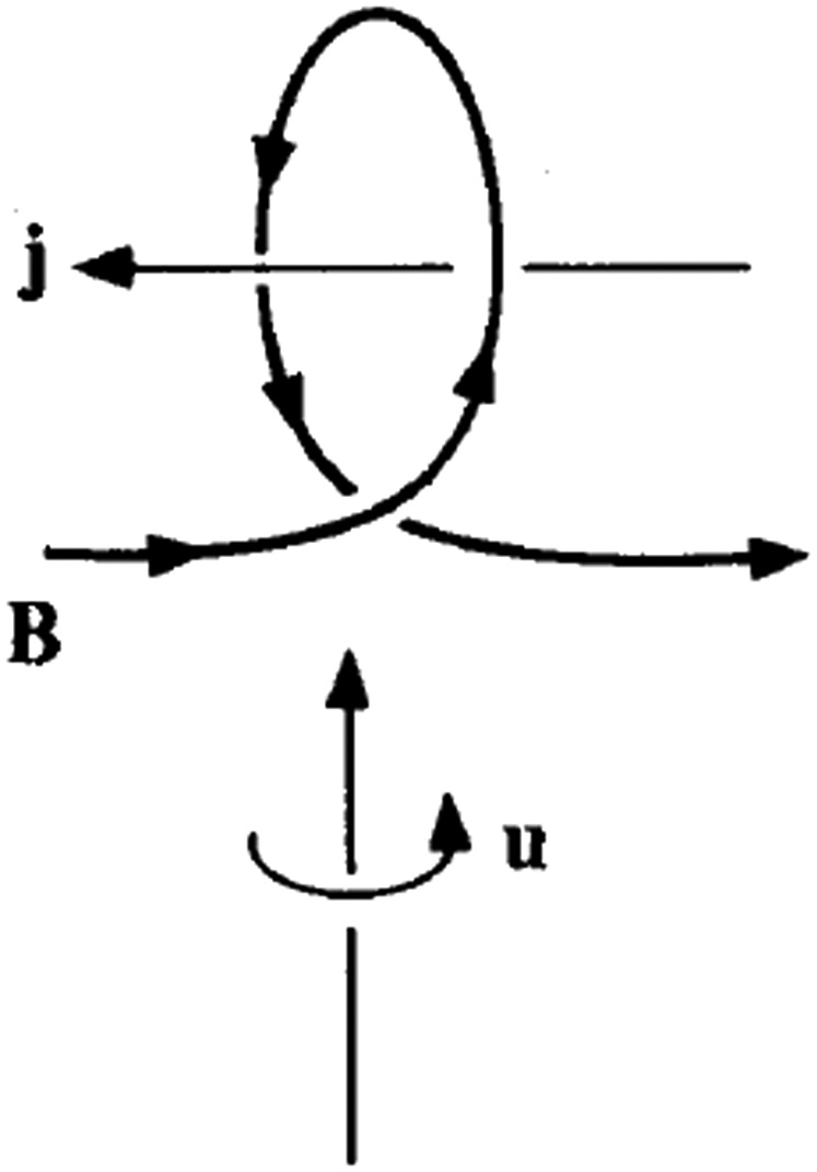
The essential mechanism of the α-effect.
I discussed this mean-field electrodynamics at length in my 1978 monograph (27), and it would be inappropriate to elaborate on this here. It is enough to note that, since ℰ is a pure vector, whereas B is a pseudovector, the coefficient α is, like helicity, a pseudoscalar, and is therefore nonzero only if the turbulence is chiral, i.e., lacks reflection symmetry. When the magnetic Reynolds number of the turbulence is small, i.e., for large fluid resistivity η, the magnetic field responds in a quasistatic manner to the fluctuating velocity field, and there is then a well-established relationship between α and the helicity spectrum function  of the turbulence:
 |
Introducing a vector potential a for u such that  and
and  , this result may be written equivalently (cf. ref. 28, equation 3.58) as
 |
This formula relates α to the mean linkage, not of the vortex lines, but of the streamlines of the velocity field, a fact that has not, to my knowledge, been noted previously. With the inclusion of the α-effect, the induction equation for the mean field B becomes
 |
and, on a sufficiently large scale, the first term on the right-hand side always dominates. It is obvious from this equation that any field of Beltrami structure satisfying
will grow like  , with growth rate
positive provided  and
and  is small, i.e., provided the scale of B is sufficiently large. The growing field has helicity
which has the same sign as α. This behavior is dramatic: it implies that, in general, homogeneous turbulent motion in a conducting fluid medium of sufficiently large extent will always give rise to spontaneous growth of a large scale magnetic field. This growth will continue until the Lorentz force  is strong enough to react back upon the turbulence, modifying it in such a way as to lead to saturation.
In realistic planetary or astrophysical contexts, there are of course many significant complications, associated with boundary conditions, anisotropy, inhomogeneity, nonstationary character of the turbulence, and mean-flow effects. However, the destabilizing α-effect is nearly always present, sometimes in disguised form, and is of crucial significance for explaining the ubiquity of magnetic fields on the cosmic scale. I regard the development of mean-field magnetohydrodynamics, as initiated by Steenbeck et al. (4), as one of the greatest achievements in turbulence research of the past half century. Nearly all subsequent research on the origins of planetary and astrophysical magnetism has taken the mean-field approach and the α-effect as a natural starting point.
An additional mechanism in almost all planetary and stellar dynamo contexts is the presence of differential rotation arising from conservation of angular momentum in convecting rotating systems. This ω-effect generates the toroidal field from the poloidal field, whereas the α-effect drives toroidal current (anti)parallel to the toroidal field, thus (in conjunction with ohmic diffusion) regenerating the poloidal field. This dual process, described as the “ dynamo” is, in one form or another, responsible for the geomagnetic field.
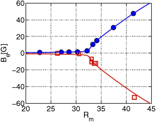
A major experimental achievement has been the reproduction of this process under laboratory conditions (5). In this VKS experiment at the Commissariat à l’Energie Atomique site in Cadarache (France), a turbulent helical flow is generated by two counter rotating propellers immersed in liquid sodium in a cylindrical copper container. These generate a mean flow with differential rotation, and superposed turbulence which presumably inherits helicity as well as energy from its interaction with the mean flow. As the magnetic Reynolds number  based on the rotational speed of the propellers is increased, a critical value
  is reached above which a magnetic field grows spontaneously on the scale of the container from an initially low level (Fig. 5). The field grows until the quadratic Lorentz force is strong enough to react back upon the turbulence, presumably suppressing the α-effect. The growing field can be of either polarity, consistent with the invariance of the MHD equations under the substitution
  . This is a supercritical bifurcation, although one of rather unusual structure. The dynamo is almost certainly of
  type; certainly it depends on the influence of the turbulence, for without this, the flow is axisymmetric and dynamo action is then known to be impossible (29).
Fig. 5.
Dynamo action in the VKS experiment; measurements of azimuthal field component when propellers counter-rotate in non-scooping direction (blue circles), or scooping direction (red squares); in either case field can grow with either polarity, consistent with  symmetry of MHD equations. The blue and red curves are best fit to Bθ ∼ (Rm-32)0.77 above the bifurcation threshold.[Reproduced with permission from ref. 5 (Copyright 2009, AIP Publishing).]
There is however one feature of the experiment that is not yet well understood. Dynamo action occurs when the propellers are made from soft iron, but not when they are made from copper. When dynamo action occurs, the iron itself becomes magnetized, and this evidently helps the dynamo process. It seems likely that the same type of dynamo will function with propellers of copper (whose conductivity is comparable with that of liquid sodium) but at a significantly higher value of  than attained in the VKS experiment (which unfortunately has now been decommissioned).
Several other ambitious experiments are however under development with a view to a more realistic simulation of the geodynamo in a spherical geometry; for an informal discussion of these experiments, from which results are eagerly awaited, see ref. 30.
Analogous Euler Flows and Coherent Structures
There is a further potent analogy between magnetostatic equilibria described by the equations
and the steady Euler equations when written in terms of vorticity,
where h is the Bernoulli “head.” The analogy here is evidently between the variables
where  is an arbitrary reference pressure. The analogy implies that, if by any means (e.g., magnetic relaxation) we find a solution of the magnetostatic Eq. 20, then (provided the boundary conditions also correspond) we have simultaneously found a corresponding solution of the steady Euler equations. Note that current sheets in the magnetostatic solutions translateto vortex sheets in the steady Euler solutions.
Interesting although this is, we cannot push the analogy too far, because it applies only to the steady states, but not to the stability of these states when perturbed. As already remarked, the magnetostatic equilibria found by the relaxation process are stable under ideal conditions (being minimum-energy states). However, the analogous Euler flows are not minimum-energy states with respect to perturbations compatible with the unsteady Euler equations. These perturbations, known as “isovortical,” respect the frozen-in character of the vorticity field (which here is not the analog of the magnetic field). A sufficient condition for the stability of steady Euler flows is that the kinetic energy should be either maximal or minimal with respect to isovortical perturbations (31). It has been shown however (32) that this condition is rarely satisfied for fully 3D flows, and that such flows are therefore definitely prone to instability. Indeed the presence of vortex sheets almost ensures that such flows will be subject to Kelvin–Helmholtz instability localized near these sheets.
Consider now a turbulent flow, governed by the unsteady Navier–Stokes equation in the form
 |
and suppose that in some regions within the turbulence the helicity density  is maximal or near maximal, so that u is nearly parallel to
  . Then in such regions the nonlinear term
  of (23) is small, so that a reduction in the nonlinear cascade of energy to smaller scales is to be expected. Thus, it would appear that the main effect of helicity in turbulent flow should be to inhibit this (Kolmogorov) cascade; and indeed the flow structures in regions where
  is near maximal should for this reason tend to persist coherently in time; they are thus good candidates as the coherent structures of turbulence, about which much has been written (see, for example, ref. 33).
One might therefore expect some anticorrelation between helicity density  and the local rate of dissipation of turbulent kinetic energy. However, direct numerical simulation of homogeneous turbulence (34) has shown no such anticorrelation; see also ref. 35 for experimental measurement of helicity density. A difficulty here is that, as recognized in ref. 34,
  is not Galilean invariant (although its space average is), so care is needed to choose the most appropriate frame of reference in identifying coherent structures.
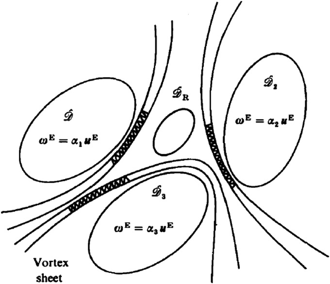
However that may be, the idealized picture of turbulence (24) sketched in Fig. 6 may have some merit: coherent structures in which  is near maximal make grazing contact on vortex sheets which are subject to Kelvin–Helmoltz instability; the resulting spiral wind-up of these sheets is the essential mechanism whereby transfer of energy to smaller scales occurs. This instability leads to the formation of concentrated vortices which are stretched and progressively thinned down to the Kolmogorov scale at which dissipative reconnection, much as in the idealized experiment of ref. 3, can destroy mean-square vorticity. Although speculative, this appealing scenario may perhaps provide continuing motivation for computational and experimental investigation.
Fig. 6.
Idealized structure of turbulent flow: coherent structures, each of near-maximal helicity, are separated by vortex sheets which are each subject to Kelvin–Helmholtz instability. [Reproduced with permission from ref. 24 (Copyright 1985, Cambridge University Press).]
Slow Viscous Flows: Some Topological Surprises
In slow viscous flows (i.e., those for which the Reynolds number  is very small, where U and L are characteristic velocity and length scales of the flow), inertia forces are negligible in a first approximation; such flows are quasistatic and are described by the Stokes equations
where  , the dynamic (as opposed to kinematic) viscosity. Taking the curl of this equation, the vorticity satisfies Laplace’s equation
If the velocity is prescibed on the fluid boundary in a manner compatible with the incompressibility of the fluid, then it is well known that the resulting Stokes flow is unique, and dissipates kinetic energy at a lower rate than any other kinematically possible flow satisfying the same boundary conditions. It might be thought that such flows, being solutions of the simple linear system (24), should have a correspondingly simple structure with little topological complexity. The following three problems, with which I have been involved, may serve to show that this is by no means always the case.
Corner Eddies.
Any 2D flow may be described by a streamfunction  , the velocity field being then
  , and the vorticity
  . Eq. 25 immediately shows that ψ satisfies the biharmonic equation
The topology of a 2D flow may be best described in terms of the maxima and minima of ψ, each determining the center of an eddy, anticlockwise or clockwise, respectively. The first surprise is that, for flow in a bounded region, the number of such eddies can be unbounded. The prototype example is flow in a corner region bounded by planes  and driven by some stirring mechanism far from the corner. It turns out that, when the angle
  of the corner is less than a critical value (about 147°), the stream function ψ exhibits infinite oscillations as the distance r from the corner tends to zero. The asymptotic solution of the Stokes equation near the corner is, in the terminology of ref. 36, a similarity solution of the second kind; in fact, from this solution, one finds that, on the centerline
  ,
,
where  and
and  depend on α, and c is an undetermined phase. This implies an infinite geometric sequence of eddies of alternating sense (37, 38), with a damping factor of at least 300 from one eddy to the next as the corner is approached (see Fig. 7 for the situation when
  ). I presented this work (37) at the Polish Fluid Dynamics Symposium held in Zakopane in September 1963, at which a number of Russian scientists were present. Shortly after this, I received from G. I. Barenblatt, then at the Institute of Mechanics of Moscow University, a photograph giving clear evidence of the onset of the sequence of corner eddies. The large damping factor means that in practice only one, or at most two, of these corner eddies are observable experimentally in the steady state. Photographs of corner eddies for a wide variety of steady flows were published by Taneda (39); one of these is reproduced in Fig. 8. Of course, if the corner is slightly rounded, as it always is in practice, then the number N of eddies in the sequence is finite, N tending to infinity as the radius of curvature at the corner tends to zero.
Fig. 7.
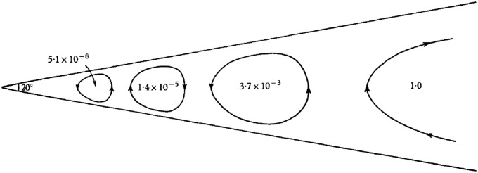
Corner eddy structure from asymptotic solution. [Reproduced with permission from ref. 38 (Copyright 1964, Cambridge University Press).]
Fig. 8.
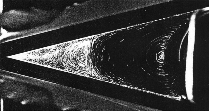
First and second corner eddies observed experimentally; subsequent eddies in the geometric sequence are too weak to be observed. [Reproduced with permission from ref. 39 (Copyright 1979, The Physical Society of Japan).]
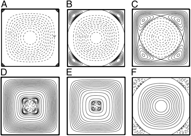
Such eddies are found in a huge variety of situations, and many variations on the original theory have been elaborated. For example, if a cylindrical container of square cross-section is oscillated sinusoidally about its central axis, a flow structure appears (relative to the fluid boundary) in which eddies appear to grow from the corners, ultimately resulting in flow reversal in the interior in each half-period (Fig. 9) (40).
Fig. 9.
Streamlines of flow relative to an oscillating square fluid domain: eddies emerge from the corners during each half-period, and propagate toward the center, effecting flow reversal in the process. (A) t = 0. (B) t = 0.61. Primary corner eddies, rotating in opposite sense to the central eddy, grow inwards. (C) t = 0.94. Dividing streamlines detach from the walls and create a heteroclinic connection. (D) t = 1.38. (E) t = 1.41. This connection shrinks and eventually annihilates the central eddy. (F) t = π + 0.55. The next flow reversal progresses in a similar way. [Reproduced with permission from ref. 40 (Copyright 2006, Cambridge University Press).]
Lagrangian Chaos in Steady Stokes Flows.
A second surprise concerns 3D steady Stokes flows: the particle paths of such flows may be chaotic, in the sense that the separation of initially adjacent particles may diverge exponentially in time! This behavior is commonly associated with high Reynolds number turbulence, but here we encounter the phenomenon at the opposite extreme of low Reynolds number steady flow; this behavior is of great relevance to mixing processes in microfluidic devices, as reviewed by Squires and Quake (41).
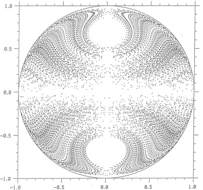
The first family of Stokes flows exhibiting this phenomenon of Lagrangian chaos was found by Bajer and Moffatt (42). These flows, quadratic in the Cartesian coordinates  , are confined to a sphere and are driven by a suitable distribution of tangential velocity at its surface; they generally have nonzero helicity. Particle paths were computed and Poincaré sections constructed for some of these flows, showing the successive points at which any particle crosses a diametral plane. Fig. 10 shows such a Poincaré section; it crosses the plane 40,000 times, a number limited only by the finite computing time. The scatter of points is a clear indication of chaos. Similar behavior has been found for flows inside a spherical droplet immersed in a rotational flow, the interior flow being in this case cubic in the coordinates
  (43).
(43).
Fig. 10.
Poincarè section for a steady Stokes flow in a sphere. [Reproduced with permission from ref. 42 (Copyright 1990, Cambridge University Press).]
Free-Surface Cusps.
The third surprise concerns the deformation of the free surface of a viscous fluid subjected to subsurface stirring. In regions where the surface flow converges toward a line, the surface can dip downward forming a sharp cusp, as depicted in Fig. 11, and this despite the smoothing action of surface tension γ. The relative importance of viscous and surface tension effects is measured by the capillary number  , where U is a characteristic subsurface velocity; when
  , viscosity and surface tension are of comparable importance: It is a level playing field. Let L be a characteristic scale (e.g., the gap between the cylinders in Fig. 11) and let R be the radius of curvature at the incipient cusp. Dimensional arguments imply that
  , for some function F, and one might therefore guess that when
  ,
,  should be of order unity, i.e., perhaps as small as 0.01, say, but not much smaller. However, here is the surprise: for an idealized problem in which the stirring is represented by a vortex dipole at depth L, an exact solution of the Stokes equations satisfying the nonlinear free-surface boundary conditions gives (44)
so, when  ,
,  , the smallest number of order unity ever encountered in a fluid dynamical context. This number (effectively zero) implies that, in physical if not mathematical terms, a cusp does indeed form.
Fig. 11.
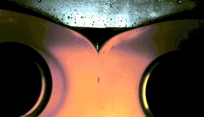
Free-surface cusp on golden syrup formed by counter rotation of two subsurface cylinders.
As shown in ref. 45, this singularity may be resolved by taking account of the build-up of air pressure in the immediate vicinity of the cusp. However, a moral may be drawn from the result 28: while dimensional arguments are illuminating in the preliminary analysis of fluid dynamical problems, they must be supplemented wherever possible by exact solutions of the governing differential equations.
Acknowledgments
I thank Konrad Bajer, Michal Branicki, Atta Chui, Jae-Tak Jeong, Yoshifumi Kimura, and Renzo Ricca for collaboration on some of the topics discussed in this article. I also thank the referees for their valuable comments, which have led to significant improvements in presentation.
Footnotes
The author declares no conflict of interest.
See Profile on page 3650.
References
- 1.Moffatt HK. The degree of knottedness of tangled vortex lines. J Fluid Mech. 1969;35:117–129. [Google Scholar]
- 2.Thomson W. Hydrodynamics and General Dynamics. Cambridge, UK: Cambridge Univ Press; 1910. Mathematical and Physical Papers, Vol. 4. [Google Scholar]
- 3.Kleckner D, Irvine WTM. Creation and dynamics of knotted vortices. Nat Phys. 2013;9:253–258. [Google Scholar]
-
4.Steenbeck M, Krause K, Rädler K-H. Berechnung der mittleren Lorentz-Feldstärke
 fur ein elektrisch leitendes Medium in turbulenter, durch Coriolis-Kräfte beinfluster Bewegung. Z Naturforsch B. 1966;21A:369–376. [Google Scholar]
 - 5.Monchaux R, et al. The von Kármán sodium experiment: Turbulent dynamical dynamos. Phys Fluids. 2009;21:035108. [Google Scholar]
- 6.Moffatt HK. The energy spectrum of knots and links. Nature. 1990;347:367–369. [Google Scholar]
- 7.Katritch V, et al. Geometry and physics of knots. Nature. 1996;384:142–145. [Google Scholar]
- 8.Moffatt HK, Bajer K, Kimura Y. Topological fluid dynamics: Theory and application. Procedia IUTAM. 2013;7:1–260. [Google Scholar]
- 9.Bates A, Buck D, Harris S, Stasiak A, Sumners DW. Topological aspects of DNA function and protein folding. Biochem Soc Trans. 2013;41(2) doi: 10.1042/BST20130006. [DOI] [PubMed] [Google Scholar]
- 10.Ashton T, Cantarella J, Piatek M, Rawdon E. Knot tightening by constrained gradient descent. Experim Math. 2011;20:5790–5635. [Google Scholar]
- 11.Buniy RV, Kephart TW. Glueballs and the universal en- ergy spectrum of tight knots and links. Int J Mod Phys A. 2005;20:1252–1259. [Google Scholar]
- 12.Helmholtz H. Über Integrale der hydrodynamischen Gleichungen, welche den Wirbelbewegungen entsprechen. J für die reine und angew Math. 1858;55:25–55. [Google Scholar]
- 13.Woltjer L. A theorem on force-free magnetic fields. Proc Natl Acad Sci USA. 1958;44(6):489–491. doi: 10.1073/pnas.44.6.489. [DOI] [PMC free article] [PubMed] [Google Scholar]
- 14.Batchelor GK. On the spontaneous magnetic field in a conducting liquid in turbulent motion. Proc R Soc Lond. 1950;201:405–416. [Google Scholar]
- 15.Betchov R. Semi-isotropic turbulence and helicoidal flows. Phys Fluids. 1961;4:925–926. [Google Scholar]
- 16.Moreau JJ. Constantes d’un îlot tourbillonnaire en fluid parfait barotrope. C R Acad Sci Paris. 1961;252:2810–2812. [Google Scholar]
- 17.Cǎlugǎreanu G. L’intégral de Gauss et l’analyse des noeuds tridimensionnels. Rev Math Pures Appl. 1959;4:5–20. [Google Scholar]
- 18.Cǎlugǎreanu G. Sur les classes d’isotopie des noeuds tridimensionnels et leurs invariants. Czech Math J. 1961;11:588–625. [Google Scholar]
- 19.White JH. Self-linking and the Gauss integral in higher dimensions. Am J Math. 1969;91:693–728. [Google Scholar]
- 20.Moffatt HK, Ricca RL. Helicity and the Cǎlugǎreanu invariant. Proc R Soc Lond A. 1992;439:411–429. [Google Scholar]
- 21.Arnol’d VI. 1974. The asymptotic Hopf invariant and its applications. Proc Summer School in Differential Equations, Erevan, Armenian SSR Acad Sci, trans (1986) Sel Math Sov 5:327–345. Russian.
- 22.Freedman MH. A note on topology and magnetic energy in incompressible perfectly conducting fluids. J Fluid Mech. 1988;194:549–551. [Google Scholar]
- 23.Ruzmaikin A, Akhmetiev P. Topological invariants of magnetic fields, and the effect of reconnections. Phys Plasmas. 1994;1:331. [Google Scholar]
- 24.Moffatt HK. Magnetostatic equilibria and analogous Euler flows of arbitrarily complex topology. 1. Fundamentals. J Fluid Mech. 1985;159:359378. [Google Scholar]
- 25.Chui AYK, Moffatt HK. The energy and helicity of knotted magnetic flux tubes. Proc R Soc Lond A. 1995;451:609–629. [Google Scholar]
- 26.Parker EN. Hydromagnetic dynamo models. Ap J. 1955;122:293. [Google Scholar]
- 27.Moffatt HK. Magnetic Field Generation in Electrically Conducting Fluids. Cambridge, UK: Cambridge Univ Press; 1978. [Google Scholar]
- 28.Krause F, Rädler K-H. Mean-Field Magnetohydrodynamics and Dynamo Theory. Oxford: Pergamon; 1980. p. 271. [Google Scholar]
- 29.Cowling TG. The magnetic field of sunspots. Mon Not R Astron Soc. 1933;94:39–48. [Google Scholar]
- 30.Lathrop DP, Forest CB. Magnetic dynamos in the lab. Phys Today. 2011;64(July):40–45. [Google Scholar]
- 31.Arnol’d VI. Sur un principe variationnel pour les écoulementss stationnaires des liquides parfaits et ses applications aux problèmes de stabilité non-linéaires. J Mec. 1966;5:29–43. [Google Scholar]
- 32.Rouchon P. On the Arnol’d stability criterion for steady-state flows of an ideal fluid. Eur J Mech BFluids. 1991;10:651–661. [Google Scholar]
- 33.Hussain AKMF. Coherent structures and turbulence. J Fluid Mech. 1986;173:303–356. [Google Scholar]
- 34.Rogers MM, Moin P. Helicity fluctuations in incompressible turbulent flows. Phys Fluids. 1987;30:2662. [Google Scholar]
- 35.Wallace JM, Balint J-L, Ong L. An experimental study of helicity density in turbulent flows. Phys Fluids A. 1992;4:2013. [Google Scholar]
- 36.Barenblatt GI. Scaling, Self-Similarity, and Intermediate Asymptotics: Dimensional Analysis and Intermediate Asymptotics. Cambridge, UK: Cambridge Univ Press; 1996. [Google Scholar]
- 37.Moffatt HK. Viscous eddies near a sharp corner. Arch Mech Stosowanej. 1964;2(16):365–372. [Google Scholar]
- 38.Moffatt HK. Viscous and resistive eddies near a sharp corner. J Fluid Mech. 1964;18:1–18. [Google Scholar]
- 39.Taneda S. Visualization of separating Stokes flows. J Phys Soc Jpn. 1979;46:1935–1942. [Google Scholar]
- 40.Branicki M, Moffatt HK. Evolving eddy structures in oscillatory Stokes flows in domains with sharp corners. J Fluid Mech. 2006;551:63–92. [Google Scholar]
- 41.Squires TM, Quake SR. Microfluidics: Fluid physics at the nanoliter scale. Rev Mod Phys. 2005;77:977–1026. [Google Scholar]
- 42.Bajer K, Moffatt HK. On a class of steady confined Stokes flows with chaotic streamlines. J Fluid Mech. 1990;212:337–364. [Google Scholar]
- 43.Stone HA, Nadim A, Strogatz SH. Chaotic streamlines inside drops immersed in steady Stokes flows. J Fluid Mech. 1991;232:629–646. [Google Scholar]
- 44.Jeong J-T, Moffatt HK. Free-surface cusps associated with flow at low Reynolds number. J Fluid Mech. 1992;241:1–22. [Google Scholar]
- 45.Eggers J. Air entrainment through free-surface cusps. Phys Rev Lett. 2001;86(19):4290–4293. doi: 10.1103/PhysRevLett.86.4290. [DOI] [PubMed] [Google Scholar]


