Abstract
In the present study, the exfoliation of natural graphite (GR) directly to colloidal GR/graphene (G) nanostructures using collagen (CL) was studied as a safe and scalable process, akin to numerous natural processes and hence can be termed “biomimetic”. Although the exfoliation and functionalization takes place in just 1 day, it takes about 7 days for the nano GR/G flakes to stabilize. The predominantly aromatic residues of the triple helical CL forms its own special micro and nanoarchitecture in acetic acid dispersions. This, with the help of hydrophobic and electrostatic forces, interacts with GR and breaks it down to nanostructures, forming a stable colloidal dispersion. Surface enhanced Raman spectroscopy, X-ray diffraction, photoluminescence, fluorescence, and X-ray photoelectron spectroscopy of the colloid show the interaction between GR and CL on day 1 and 7. Differential interference contrast images in the liquid state clearly reveal how the GR flakes are entrapped in the CL fibrils, with a corresponding fluorescence image showing the intercalation of CL within GR. Atomic force microscopy of graphene-collagen coated on glass substrates shows an average flake size of 350 nm, and the hexagonal diffraction pattern and thickness contours of the G flakes from transmission electron microscopy confirm ≤ five layers of G. Thermal conductivity of the colloid shows an approximate 17% enhancement for a volume fraction of less than approximately 0.00005 of G. Thus, through the use of CL, this new material and process may improve the use of G in terms of biocompatibility for numerous medical applications that currently employ G, such as internally controlled drug-delivery assisted thermal ablation of carcinoma cells.
Keywords: graphene, collagen, colloid, nanostructures, biomimetic, carbon, nanomaterials, heat, thermal ablation, thermal conductivity
Introduction
The number of approaches to chemically exfoliate graphite (GR) is increasing on a daily basis because of a pressing need for its bulk synthesis. To date, the most popular chemical method for GR to graphene (G) conversion is the Hummers method, where GR is first oxidized to graphite oxide and subsequently reduced to G.1–3 The introduction of oxygen moieties and their subsequent removal introduces its own limitations. In this work, we report for the first time a direct conversion of GR/G nanostructures by an aqueous protein dispersion of type-I collagen (CL) at ambient conditions. GR is composed of an extended array of six member rings of sp2 bonded carbon atoms within each of the two-dimensional sheets, but the interactions between the sheets are by the much weaker π-bonds. Because of this, the sheets tend to slide past one another leaving zig-zag edges, close to the Fermi level.4–6 From a physical viewpoint, chemical exfoliation introduces defects in the GR layers by the attack of chemicals at the abovementioned sites. This causes the G sheets to crinkle and become relatively easy to break away from the parent stack. CL is dispersed in acetic acid (A) and there is a certain microarchitecture of the dispersion depending on the concentration of CL and A. When CL and GR are incubated together, they interact and break down into nanostructures and with time form a colloid. This seems energetically favorable as the color of the dispersion visibly changes from light to blackish grey. The reaction has no other temperature, pressure, sonication, etc requirements. This is akin to numerous natural processes and hence the process is termed “biomimetic”. Density functional theory calculations and ab initio molecular dynamics simulations have proved that binding of glycine, proline, and hydroxyproline amino acids of CL with GR is thermodynamically favorable.7 The time-kinetics of the process shows that although within 24 hours the protein attack is complete, it takes about 7 days to attain stable equilibrium. This process enables bulk synthesis of colloidal GR/G nanostructures for which no reports exist to date. Hybrid materials with novel and enhanced properties are being extensively studied, but this study is a class apart, as CL and carbon materials are connected by biological molecules. A report exists of genetically engineered proteins capable of exfoliating GR, and it is also possible that other proteins having a structure and energy matching with GR may be able to do the same.8 We report results that show CL-GR was surprisingly able to increase thermal conductivity at a very low concentration. Thus, through the use of CL, this new material and process may improve the use of graphene in numerous medical applications.
Materials and methods
Synthesis
High purity natural GR powder (product no 14734, 200 mesh size [~74 microns]; Alfa Aesar, Ward Hill, MA, USA), and CL (bovine Achilles tendon, Type I; Sigma-Aldrich, St Louis, MO, USA) were used throughout the experiments. Two percent (weight/volume [w/v]) stock CL dispersions were prepared in A and for every experiment, and were diluted to 0.5% w/v and added to GR maintaining a protein to GR ratio of 1:1 (lesser ratios are now being studied). The dispersion was incubated for 1 and 7 days (denoted as graphene-collagen [GC]1 and GC7), after which they were centrifuged at 8,000 rpm for 30 minutes, and the supernatant was used for all characterization. GR dispersed in water (GW) and in acetic acid (GA) served as controls.
Characterization
Surface enhanced Raman spectroscopy spectra was recorded in a Nicolet, AlmegaXR dispersive Raman spectrometer (Thermo Fisher Scientific, Waltham, MA, USA) (using a neodymium-doped yttrium aluminum garnet laser source, λ=532 nm) by drying a drop of the sample on a polished copper substrate for surface enhanced signals. X-ray diffraction was completed in a Bruker D8 Discover diffractometer (Billerica, MA, USA), at 40 kV with Cu-Kα radiation (λ=1.5418 Å) in the 2θ range from 6°–35°, a step size equal to 0.02°/step and a scan speed of 5 seconds/step. Photoluminescence (PL) and fluorescence (FL) were measured using a Hitachi F-4500 FL spectrophotometer (Tokyo, Japan) at an excitation wavelength of 280 nm and an emission scan range from 290–900 nm for PL and 290–450 nm for FL. X-ray photoelectron spectroscopy (XPS) spectra were recorded using a spectrometer (SPECS Surface Nano Analysis GmbH, Berlin, Germany) with a MgKα source (1,253, 6 eV). A few drops of the dispersions were dried on glass substrates and were then inserted into a vacuum chamber at 10−9 Torr. Spectra were deconvoluted using CasaXPS software (Casa Software Ltd, Teignmouth, UK), prior to which Shirley background subtraction was done. All the peaks were calibrated with respect to the standard C1s binding energy (BE) peak of pure GR at 284.5 eV. Confocal images were recorded using differential interference contrast (DIC) and FL modes using a Zeiss LSM 700 laser scanning microscope (Oberkochen, Germany) with the dye Alexa Fluor 546 (AF546; Life Technologies, Carlsbad, CA, USA); the sample was stained with rhodamine prior to imaging. A small volume (~40 μL) of the sample was transferred onto a clean microscope slide, covered with a thin (2 mm) coverslip, and directly viewed under the microscope.
Atomic force microscopy (AFM) was completed using a Seiko SPA 400 microscope (Tokyo, Japan) in the noncontact mode, at ambient conditions, using a Pyrex glass cantilever with a silicon tip; a drop of the dispersion was dried on a glass substrate, and the surface was imaged.
Transmission electron microscopy (TEM) images were recorded using a Philips CM200 microscope (Eindhoven, the Netherlands) operating at 200 kV; all dispersions were dried on carbon-coated copper grids (~300 mesh) and were then inserted into the microscope. The hydrodynamic diameter (DH), polydispersity index (PdI), and zeta potential were all measured by the DLS Nano 100 zetasizer (Malvern Instruments, Malvern, UK). Thermal conductivity was measured using a KD2 Pro thermal properties analyzer (Decagon Devices Inc., Pullman, WA, USA). The device works based on the principle of a transient hotwire method. Viscosity measurements were performed using an Ostwald viscometer, with distilled water as the reference. The values of viscosity were cross-checked using an Anton Paar automated microviscometer (Ashland, VA, USA), which works on the “falling ball through a capillary” principle.
Results and discussion
Surface enhanced Raman spectroscopy
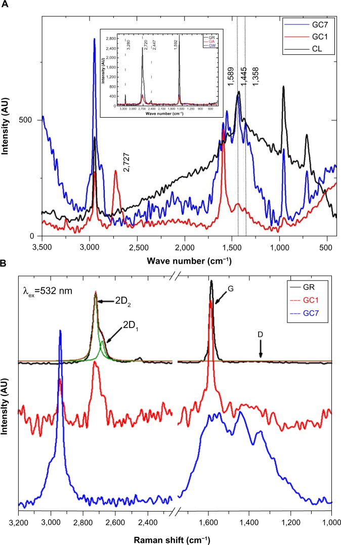
Characteristic GR peaks (spectra shown in the inset of Figure 1A and peak positions in Table 1) at 1,592 (G band) and 2,728 cm−1 (2D band) were seen, along with minor vibrational modes at 2,447 and 3,250 cm−1.9 No D band (~1350 cm−1) normally assigned to the vibrations of sp3 hybridized carbon atoms of disordered GR was seen, meaning that the precursor GR had minimal defects. Also, as expected, there was no appreciable change in the peak position of the controls, GW and GA, with respect to GR. After incubation with CL, significant changes in the GR peaks were observed: 1) The D peak (1,358 cm−1) not present in GR appeared in GC1 and increased in GC7 (it was reported previously that the D peak intensity is very weak in the single layer G but increases progressively with the number of layers,10,11 an indication of the degree of edge chirality); 2) the G band at 1,589 cm−1 was present in both GC1 and GC7, with no appreciable intensity difference; however, it splits into three peaks at 1,630, 1,589, and 1,551 cm−1 in GC7; and 3) the 2D band of GR decreased, broadened in GC1, and disappeared completely in GC7. Very few research groups have reported the complete disappearance of the 2D peak, the most noteworthy being the paper on fluorographenes.12,13 Such an observation has also been reported in misoriented G layers, where the stacking order is lost and the interlayer space (>0.342 nm) became larger than crystalline GR.14
Figure 1.
SERS spectra of CL, GC1, and GC7 is shown in (A), and in (B), SERS spectra shows 1) GR showing deconvoluted 2D1 and 2D2 bands, 2) in GC1 the 2D band broadens and splits into multiple components (≤ five-layered G), and 3) 2D band completely disappears in GC7.
Notes: (A) shows the 2D (2,727cm−1) peak in GC1 vanishes in GC7, signifying an interaction; Control spectrum is shown in the inset; In (B), the D′ band at 1,617 cm−1 absent in GR and GC1 appeared in GC7, signifying disorder.
Abbreviations: AU, arbitrary unit; CL, collagen; GA, graphite dispersed in acetic acid; GC1, 1-day graphite/collagen dispersion; GC7, 7-day graphite/collagen dispersion; GR, graphite; GW, graphite dispersed in water SERS, Surface Enhanced Raman Spectroscopy.
Table 1.
Detailed Raman peak positions of the analyzed samples corresponding to D, G, and 2D bands along with the intensity ratios (ID/IG and I2D/IG) signifying interaction
| Sample | D (cm−1) | G (cm−1) | 2D (cm−1) | ID/IG | I2D/IG |
|---|---|---|---|---|---|
| GR | – | 1,586 | 2,722 | 0 | 0.82 |
| GC1 | 1,357 | 1,589 | 2,724 | 0.27 | 0.62 |
| GC7 | 1,357 | 1,589 | – | 0.99 | 0 |
Note: Common protein peaks for GC1 and GC7: 714, 954, 1,424, 2,946 in cm−1, identified with respect to the control spectra collagen.
Abbreviations: GR, graphite; GC1, 1-day graphite/collagen dispersion; GC7, 7-day graphite/collagen dispersion.
CL used in this study had a length of 300 nm and a diameter of 1.5 nm, and we believe that CL is intercalating after every few layers of the graphitic stack. The sp3 character increases considerably (as seen from the XPS spectra) although not to the point where the material became totally amorphous, showing that the nanostructured GR flakes consist of both sp2 and sp3 domains. For the single layer G, the 2D band occurs at ~2,679 cm−1, which blue shifts to higher wave numbers by 19 cm−1 (~2,698 cm−1) for two to three layers of G; in our case the shift was even higher (~44 cm−1). The D′ band (~1,617 cm−1) appeared in GC7; the contribution from protein peaks in the same region cannot be ruled out either. With time, the transition to sp3 carbon progressed, the D peak increased in intensity, and the second order 2D vanished. The ID/IG ratio increased from 0 in GR to 0.27 in GC1, increasing further to 0.99 in GC7, clear proof that with time CL and GR are internally rearranging themselves to arrive at an equilibrium state and forming a stable colloidal G (Figure 1A). Our results suggest a transformation of GR to nanocrystalline GR, nanocrystalline GR to low sp3 amorphous carbon, and then low sp3 amorphous carbon to high sp3 amorphous carbon.15 This is supported by the position and broadening of the 2D band after 1 day and 7 days of incubation. In Figure 1B, the 2D band of GR is deconvoluted to give two components, namely 2D1 (~2,682 cm−1) and 2D2 (~2,723 cm−1). The 2D band of GC1 consists of several distinct superimposed bands; the asymmetric nature resembled that which has previously been reported to have ≤ five layers of G.16
X-ray diffraction
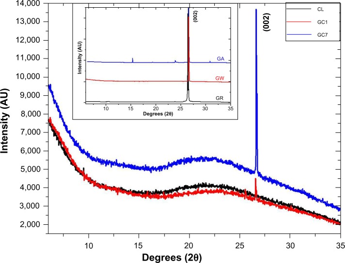
X-ray diffraction patterns of CL, GC1, and GC7 are shown in Figure 2; the control spectra of GR, GW and GA, have been plotted separately in the inset. (All the patterns are indexed with respect to the standard ICDD data, JCPDS Card No 41-1487). CL spectrum showed no peaks, just a broad hump. GC1 and GC7 spectra showed peaks at the positions 26.598° (interplanar spacing [dhkl] =3.348 Å, full width at half maximum [FWHM] =0.018) and 26.658° (dhkl =3.341 Å, FWHM =0.015), respectively. This peak is detected in all the samples corresponding to a (002) Bragg reflection of GR. In the case of GA, some minor peaks were also detected at other 2θ values (15.36°, 19.39°, 23.90°, and 30.93°), which probably appear as a result of acetate crystallization. Ideally, a single layer G is not expected to show any diffraction peak in the normal powder diffraction method. The peak increases in intensity with an increase in layer thickness. In our experimental data, the intensity profile of GC1 was three times lower than that of GC7, and in GC7 the average crystallite size increased, a measure of the coherently diffracting domains. As the concentration of GR in both GC1 and GC7 dispersions was the same, such a result can only be explained by the phenomenon of self-assembly with time in GC7. The increase in the average crystallite size also indicated that CL might have possibly been able to exfoliate the stacking in GR but was unable to break stacking away completely. The structure broke down into nanostructures, the layers aggregated but did not restack, and the resulting stable colloid was homogeneous. A detailed analysis of (002) peak position of all samples is tabulated in Table 2; the average crystallite size corresponding to the (002) peak was calculated using the Scherrer equation.17 The reported value of interlayer spacing in G is 3.4Å and for the bulk GR it is within 3.348–3.360 Å, a difference of only 0.052Å.18,19 It is apparent that even after 1 day, the CL molecules interacted substantially with GR. This is remarkable since no external energy was supplied to the reactants to overcome the π-stacking, only mutual energy balanced results in this interaction, which increased with time.
Figure 2.
X-ray diffraction peaks of CL, GC1, and GC7, and the controls are shown in the inset.
Note: Highest intensity peak was recorded at 26.67°, corresponding to (002) reflection.
Abbreviations: AU, arbitrary unit; CL, collagen; GA, graphite dispersed in acetic acid; GC1, 1-day graphite/collagen dispersion; GC7, 7-day graphite/collagen dispersion; GR, graphite; GW, graphite dispersed in water.
Table 2.
X-ray diffraction parameters that have undergone change as a result of G–C interaction
| Sample | Position (2θ, degrees) | dhkl (Å) | FWHM (2θ, degrees) | Crystallite size (nm) |
|---|---|---|---|---|
| GW | 26.640 | 3.343 | 0.051 | 157.9 |
| GA | 28.629 | 3.344 | 0.053 | 151.6 |
| GC1 | 26.598 | 3.348 | 0.018 | 427.5 |
| GC7 | 26.658 | 3.341 | 0.015 | 519.7 |
Abbreviations: dhkl, interplanar spacing; FWHM, full width at half maximum; GA, graphite dispersed in acetic acid; GC1, 1-day graphite/collagen dispersion; GC7, 7-day graphite/collagen dispersion; GW, graphite dispersed in water.
Fluorescence and photoluminescence spectroscopy
Intrinsic fluorescence (FL) in proteins is principally because of their aromatic residues and is used to assess protein conformation. An increase in FL of GC1 must be because of the contribution from the aromatic structures of GR, which with time, decreased in GC7, and a new peak appeared at around 399 nm, possibly because of charge transfer as a result of the CL-GR interaction. Delocalized π electrons and hydrophobicity drove the charge transfers between CL and GR. This is further supported by the defect-derived PL emission, which is generally very high for open structures. In contrast, FL decreases with openness (Figure 3A and B). Enhanced PL can also be explained by the protein functionalization of ≤ five-layered G that aggregate with time to form a stable sheet as seen in the TEM micrographs.20 While single/bilayer G does not exhibit PL, it is also true that the PL strength decreases considerably in thicker sheets. Surprisingly, PL in GC7 increased dramatically, indicating that the thickness of the synthesized G flake was thin enough to exhibit PL.21 This property of disordered carbon thin films containing a mixture of sp2 and sp3 domains is not new. The PL in such carbon systems is a consequence of recombination of localized electron–hole pairs in sp2 clusters, which essentially behave as the luminescence centers and varies depending on the size, shape, and fraction of the sp2 domains. PL energy scales linearly with the sp2 fraction in disordered carbon systems.22,23
Figure 3.
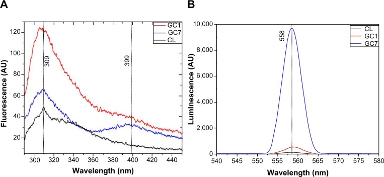
FL spectra of CL, GC1, and GC7 showing conformational changes in the protein structure (excitation wavelength ~280 nm, emission range ~290–450 nm) (A), and PL spectra of the samples proving opening up of graphitic stacks (excitation wavelength ~280 nm, emission range ~290–450 nm) (B).
Note: The decrease in FL and increase in PL correspond well with the gradual opening of the system.
Abbreviations: AU, arbitrary unit; CL, collagen; FL, fluorescence; GC1, 1-day graphite/collagen dispersion; GC7, 7-day graphite/collagen dispersion; PL, photoluminescence.
X-ray photoelectron spectroscopy
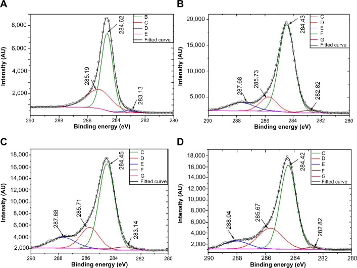
XPS is a powerful spectroscopic tool that can determine the chemical state of an element in a material and hence proves highly effective in probing G–CL interactions. Spectral parameters such as BE, FWHM, and percentage concentration corresponding to the C1s’ peak of carbon atoms present in GR, CL, GC1, and GC7 have been tabulated and are shown in Table 3. The main components in all the samples and clearly visible from the full scans (data not shown) were the C1s (~285 eV) and O1s (~534 eV) core level peaks. In addition to these, samples containing CL showed the expected N1s (~401 eV) protein signature. In GR, C1s can be deconvoluted into three peaks with BEs at 283.101, 284.624, and 285.174 eV (Figure 4A). The first, not a standard peak, may be assigned to impurities present in the precursor, the second corresponds to sp2 hybridized C=C domains, and the third to sp3 hybridized C–C domains.24–26
Table 3.
Spectral parameters showing binding energy, peak width and % concentration of deconvoluted peaks corresponding to the C1s spectra of the samples, signifying different functional species bonded with parental carbon
| Spectral parameters | Samples
|
|||
|---|---|---|---|---|
| GR | CL | GC1 | GC7 | |
| Binding energy (eV) | 285.174, 284.624, 283.101 | 287.682, 285.716, 284.433, 282.823 | 287.687, 285.716, 284.448, 283.147 | 288.042, 285.676, 284.425, 282.822 |
| Peak width (FWHM, eV) | 2.170, 0.9585, 1.323 | 2.162, 1.422, 1.305, 1.387 | 2.195, 1.622, 1.352, 1.790 | 2.068, 2.012, 1.318, 1.048 |
| % concentration | 35.16, 62.61, 2.24 | 11.60, 13.00, 73.04, 2.36 | 13.36, 19.09, 64.19, 3.36 | 9.73, 24.50, 64.34, 1.42 |
Abbreviations: CL, collagen; FWHM, full width at half maximum; GC1, 1-day graphite/collagen dispersion; GC7, 7-day graphite/collagen dispersion; GR, graphite.
Figure 4.
X-ray photoelectron spectroscopy spectra of GR (A), CL (B), GC1 (C) and GC7 (D) dispersions, suggesting interaction between CL and GR.
Notes: Inset keys: (A) B, C, D and E are the de-convoluted components of the C1s peak of GR; (B) C, D, E, F and G are the de-convoluted components of the C1s peak of CL; (C) C, D, E, F and G are the de-convoluted components of the C1s peak of GC1; (D) C, D, E, F and G are the de-convoluted components of the C1s peak of GC7.
Abbreviations: AU, arbitrary unit; CL, collagen; GR, graphite.
All other samples (Figure 4B–D) showed deconvoluted peaks at similar BEs, along with the expected additional peak within the 287–288 eV range, corresponding to C–NH2 bonds because of the presence of CL. This is the position of the pz orbital, and hence it would not be incorrect to say that CL is finding entry into the π–π* region. Since CL is dispersed in A, several functional species may be present within the same BE values, eg, >C=O (~286.45–287.92 eV), C–O (~286.21–287.53 eV), and C–NH2 (~286–288.5 eV). The peak width of sp2 C=C domains of GR (0.9585 eV, shift from GR values [Δ]=0 eV) increased in GC1 (1.352 eV, Δ=0.3935 eV) and GC7 (1.318 eV, Δ=0.3595 eV). The atomic percentage concentration also followed the same trend, GR (62.61, Δ=0), GC1 (64.19, Δ=1.58), and GC7 (64.34, Δ=1.73). Now, if we consider the sp3 C–C domains, we can clearly see that the peak width increased in GC7 (2.012 eV, Δ=0.39) with respect to GC1 (1.622 eV, Δ=0), and the percentage concentration changed for GC7 (24.50, Δ=5.41) and GC1 (19.09, Δ=0). This indicated that with time, the sp3 character increased and was associated with a change in the chemical environment of the C atom due to misalignment of the bonds. The most striking feature of the XPS spectra is the change in spectral parameters corresponding to the C–NH2 peak. The percentage concentration increased from CL (11.60) to GC1 (13.36) and then decreased in GC7 (9.73), reconfirming our belief that nanostructures exist homogeneously in clusters (also seen in the TEM).
The GC1 sheets must be within the nanometer range of each other for the effect of edge atoms to become pronounced and for the edges to interact with each other to remain as a stable colloidal system. CL converts GR into G nanoflakes. The broadening remains unaffected (2.162 eV in CL, 2.195 eV in GC1, and 2.068 eV in GC7), meaning that as predicted, the protein attack on GR stacks is complete after the first day of incubation. A further observation is the intensity (counts per second [cps]) of the π–π* satellite peak of the four samples at 290 eV. Intensity is the lowest for the GR (857 cps) and the highest for CL (2,245 cps), with GC1 (2,062 cps) and GC7 (1,288 cps) in between, further supporting our observation of a sp2 to sp3 transition.
Confocal microscopy
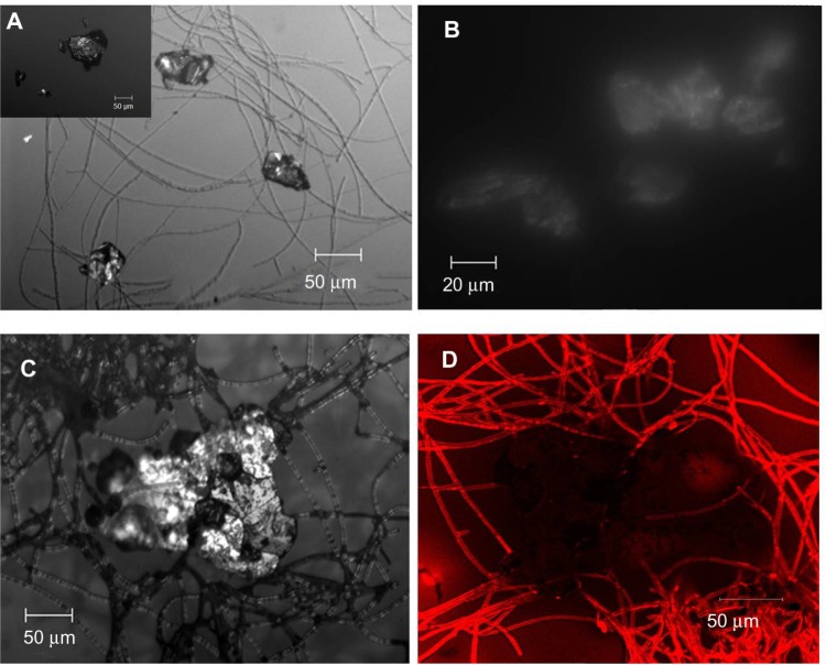
Confocal FL microscopy is an established three-dimensional imaging technique in biological science; however, its application in colloidal and polymeric systems is just beginning to be explored. In addition to confocal FL microscopy, optical imaging is also being extensively used to characterize G and determine its thickness.27,28 Whenever a sparingly soluble biopolymer is used as a reactant, the microenvironment differs from that of solution chemistry; it is more reactive because of the presence of dangling/broken/sacrificial bonds. This structural similarity of CL with GR zig-zag edges leads to energy balance and favorable electrostatic and hydrophobic interactions. We were fortunate to image at 10×, 20×, and 50× magnifications and view the global picture of a drop of the fluid itself. It shows how the GR flakes were engulfed at different sites in the mesh of CL fibrils (Figure 5A).
Figure 5.
Confocal micrographs of GC7 showing G clusters attached to CL strands (A) (GW shown in the inset), self-assembly of G flakes (B), CL attack at the G edges (C), and fluorescent image showing presence of CL within G (D).
Notes: The corresponding fluorescence image in Figure 5D shows that the large G flake (~200 μm) is not only surrounded by the fluorescing CL fibrils, but the fibrils have even penetrated the flakes from all sides.
Abbreviations: CL, collagen; G, graphene; GC7, 7-day graphite/collagen dispersion; GW, graphite dispersed in water.
Further, the kinetics of this process after 7 days can be explained from the captured confocal images, both in fluorescent and DIC modes. DIC imaging is an optical imaging technique that shows the differential contrast of a material arising from the differences in refractive index of specimen components. It transforms the path difference of laser light while traversing through the material into detectable amplitude differences proportional to the object’s thickness. In our case, such differences can also arise due to the surface adherence of CL at the GR/G surface and the edges. This probably breaks GR down to smaller GR flakes, increasing the reflectivity in the process. Previous reports29 have shown that the refractive index of GR differs from that of G; in our results it could be either due to 1) protein functionalization or 2) the decrease in the number of layers of the GR flakes, and/or 3) subsequent self-assembly of the G flakes into stable clusters. With respect to GW (Figure 5A inset), the reflectivity changes dramatically and is clearly shown in Figure 5B. Figure 5C is the magnified image of Figure 5A, which shows more clearly how the CL fibrils anchor to the GR flake, here the reflectivity difference is more pronounced. The DIC and fluorescent images are inverted when observed in fluorescence mode (appears as dark patches). The corresponding fluorescence image in Figure 5D shows that the large G flake (~200 μm) is not only surrounded by the fluorescing CL fibrils, but the fibrils have even penetrated the flakes from all sides.
Atomic force microscopy
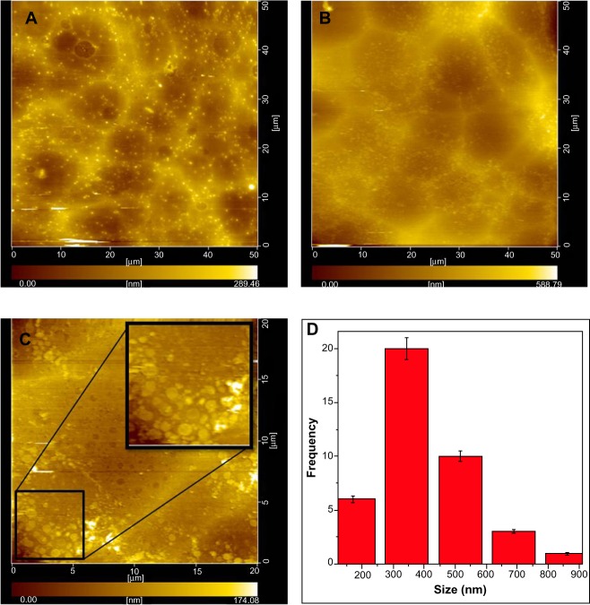
AFM topography images shown in Figure 6 are that of scan areas (50 μm×50 μm) of the control CL (Figure 6A), GC7 (Figure 6B), and GC7 (Figure 6C) and the histogram (Figure 6D) of the flake size distribution from an enlarged area of GC7 (Figure 6C). The presence of a hazy film in Figure 6B as compared to the control (Figure 6A) became more prominent when a detailed scan was done (Figure 6C). Flakes of varying sizes were formed depending on the reaction kinetics of the process; a histogram of the flake size distribution was plotted and matched well with the TEM data.
Figure 6.
Noncontact AFM images of CL (A) and GC7 (B) on glass (focus area equal to 50 μm × 50 μm) showing topography and a magnified image of an area of GC7 (20 μm × 20 μm) (C) showing G flakes (inset) and the histogram showing a maximum frequency in 300–350 nm range (D).
Abbreviations: AFM, atomic force microscopy; CL, collagen; GC7, GC7, 7-day graphite/collagen dispersion.
Transmission electron microscopy and dynamic light scattering
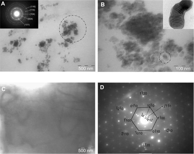
TEM images of the GC7 sample (Figure 7A–D) show the self-assembled nanoclusters of the flakes torn away from GR stacks (200 mesh: starting GR size is about 74 μm) that further broke into smaller fragments. CL binding to GR must be due to inductive charge destabilization, resulting in the disturbance of the π–π stacking of the layers in GR, a phenomenon dictated by the similarity of the interacting molecular structures. The entire length scale from confocal and TEM showed that the few layers of GR did not restack but remained misaligned post CL interaction. The indexed selected area electron diffraction ring patterns shown in the inset of Figure 7A matches that of polycrystalline GR. It must be mentioned, that any nanosized polycrystalline G will show ring patterns that can be reverted back into hexagonal patterns by changing the sample tilt angle by 90°. The spotted area has been magnified and is shown in Figure 7B, which consists of numerous dumbbell shaped structures, dictated perhaps by the structure of the CL fibrils; thickness contours of G edges shown in the inset are in the order of 3 nm. If one considers the intergraphitic layers equal to 0.33 nm and the diameter of the CL triple helix as 1.5 nm, the flakes consist of G having ≤ five-layer thickness. Figure 7C shows a very stable G flake, 0.5 μm in length; the surface contours of which indicated the formation of five-layered G. The corresponding normal incidence selected area electron diffraction pattern (Figure 7D) taken from the same area clearly reveals the hexagonal symmetry in the entire 0.5 μm range; the intensity of the spots corresponding to planes appears to be brighter than the spots, an observation well reported for few G layers, and it is this intensity modulation which proved exfoliation most authentically.
Figure 7.
Bright field TEM image of colloidal G with indexed SAED pattern (A) (inset), magnified image of the spotted area in (A) showing self assembled folded G flakes consisting of dumbbell shaped structures (B) (inset), free standing few-layer G (C), and the corresponding SAED pattern showing hexagonal symmetry (D).
Notes: R1 and R2 are the radius vectors measured from the central beamline to the diffraction spots.
Abbreviations: G, graphene; SAED, selected area electron diffraction, TEM, transmission electron microscopy.
Dynamic light scattering results (not shown) are complementary to the TEM data. The DH of the CL dispersion was 536.6 nm and PdI equal to 0.25. After 7 days of incubation in GC7, the interactions between CL and G stabilized, and the G flakes tended to self-assemble into a more compact system. As a result, the DH decreased to 406.8 nm and the PdI increased to 0.41, possibly due to the assembled G flakes, and the zeta potential (+27.6 mV) was close to the stable range of colloids.
Thermal conductivity and viscosity measurements
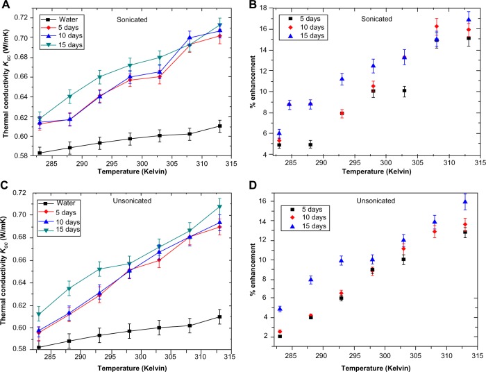
Recent work on nanofluid heat transfer has shown that carbon nanotube-based nanofluids exhibit excellent thermal properties.30 With the discovery of G, studies have been initiated to measure the heat transport properties of G nanofluids.31 A fluid containing G is expected to increase the thermal conductivity tremendously, which can revolutionize biomedical therapeutics such as controlled drug-delivery assisted internal thermal ablation of carcinoma cells. However, no work has been reported where protein assisted G colloids have been tested as potential thermofluids for hyperthermia treatments, making our work significant in this regard. The thermal conductivity measurements of GC7 showed interesting results; all comparisons were made with respect to distilled water as the base medium. Data sets were recorded by varying the temperature periodically from 283 K (10°C) to 313 K (40°C) at an interval of 5 K after 5, 10, and 15 days. Figure 8A and B shows the increase in thermal conductivity of the sonicated sample with rising temperature, followed by the percentage enhancement, while in Figure 8C and D, the values for the unsonicated sample are shown. The percent enhancement was calculated from the equation,
Figure 8.
Thermal conductivity of colloidal GR nanostructures after sonication (A), corresponding % enhancement (B), thermal conductivity of colloidal GR unsonicated nanostructures (C), and corresponding % enhancement (D).
Abbreviation: GR, graphite.
| (1) |
where KGC is the thermal conductivity of colloidal G, and K0 is the thermal conductivity of distilled water. Considering the fact that both the samples had the same volume fraction of G (~0.00005), it was observed that after sonication the enhancement was higher compared to the unsonicated sample. The highest recorded enhancement after sonication was 16.8 after 15 days, followed by 15.9 after 10 days and 15.1 after 5 days; all values were recorded at 313 K (40°C). The increase in conductivity with temperature followed a linear trend for both the samples; however, it was also observed that the increase was only marginal after 5 and 10 days but increased more after 15 days. The values remained constant at this value when the experiments were conducted a 4th and 5th time after a month. The increase and final stabilization of the thermal conductivity of the fluid can be treated as qualitative evidence for the transient exfoliation of GR by CL to form G. The fact that in the early experiments the thermal conductivity increments were lower than the later experiments implies that GR (thermal conductivity lower than that of G) has yet to be completely transformed. With time, the thermal conductivity rises, implying gradual transformation of the remaining GR to GR nanostructures. At the end of the transformation process, wherein the GR was completely exfoliated to G, the thermal conductivity value reached a standstill, and further incremental changes with time were not possible for a particular sample. This final value is the highest thermal conductivity that can be obtained for a fixed sample with a fixed concentration of GR. The fact that with a very low volume fraction of G in dispersion, where G is less than 0.00005 (volume fraction not estimated accurately), we obtained nearly a 17% rise in conductivity, which gives ample scope for further studies with protein chemistry synthesizing better G colloids.
The viscosity data for both the fluids was just 10%–15% higher than the base fluid viscosity (Figure 9). The values at a given temperature were found to be within 5% of each other. The low viscosity of the fluids is of great utility if they are used as carrier fluids in biomedical applications such as targeted drug delivery and intratumor injections for laser-assisted hyperthermia. Moreover, through the addition of CL, better biocompatibility should result, however, this remains to be tested.
Figure 9.
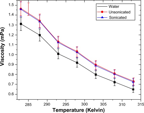
Viscosity of water, unsonicated, and sonicated samples.
Conclusion
The ability to produce stable colloidal G flakes in bulk is itself an achievement. The main challenge that remains, even today, in G synthesis, is to produce a large enough volume of G in a safe and cost-efficient manner. All studies support the observation that CL helps in the exfoliation and breaking away of layers from the parent GR stacks into colloidal nanostructures. AFM shows an average flake size of 350 nm, and TEM conclusively proves the exfoliation of GR and the increase of sp3 character. PL in GC7 increased dramatically, indicating that the thickness of the synthesized G flake was thin enough to exhibit PL, the sp2 clusters behave as luminescence centers, and PL energy scales linearly with the sp2 fraction. The high enhancement in thermal conductivity of GC colloids at a low volume fraction of G, with minute increases in the viscosity, qualifies the fluid as a novel bionanofluid for possible applications in intratumor injections for laser assisted hyperthermia, biocompatible drug carrier for magnetohyperthermia of deep seated carcinoma tissues, and for targeted drug delivery to internal organs. The stability of the samples gives ample scope for increasing the G content in the colloid by modifying the protein conformation.
Acknowledgments
The authors acknowledge the contributions of M Ghosh, NR Bandyopadhyay, and Subhabrata Chakraborty for TEM characterization. S Bhattacharya also acknowledges the research support of CSIR-Senior Research Fellowship from the Government of India.
Footnotes
Disclosure
The authors report no conflicts of interest in this work.
References
- 1.Geim AK, Novoselov KS. The rise of graphene. Nat Mater. 2007;6:183–191. doi: 10.1038/nmat1849. [DOI] [PubMed] [Google Scholar]
- 2.Rao CNR, Sood AK, Subrahmanyam KS, Govindaraj A. Graphene: the new two-dimensional nanomaterial. Angew Chem Int Ed. 2009;48(42):7752–7777. doi: 10.1002/anie.200901678. [DOI] [PubMed] [Google Scholar]
- 3.Hummers WS, Offeman RE. Preparation of graphitic oxide. J Am Chem Soc. 1958;80(6):1339–1339. [Google Scholar]
- 4.Miyamoto Y, Nakada K, Fujita M. First-principles study of edge states of H-terminated graphitic ribbons. Phys Rev B. 1999;59(15):9858–9861. [Google Scholar]
- 5.Fujita M, Wakabayashi K, Nakada K, Kusakabe K. Peculiar localized state at zigzag graphite edge. J Phys Soc Jpn. 1996;65:1920–1923. [Google Scholar]
- 6.Okada S, Oshiyama A. Magnetic ordering in hexagonally bonded sheets with first-row elements. Phys Rev Lett. 2001;87(14):146803–146806. doi: 10.1103/PhysRevLett.87.146803. [DOI] [PubMed] [Google Scholar]
- 7.Cazorla C. Ab initio study of the binding of collagen amino acids to graphene and A-doped (A = H, Ca) graphene. Thin Solid Films. 2010;518(23):6951–6961. [Google Scholar]
- 8.Laaksonen P, Kainlauri M, Laaksonen T, et al. Interfacial engineering by proteins: exfoliation and functionalization of graphene by hydrophobins. Angew Chem Int Ed. 2010;49(29):4946–4949. doi: 10.1002/anie.201001806. [DOI] [PubMed] [Google Scholar]
- 9.Wang Y, Alsmeyer DC, McCreery RL. Raman spectroscopy of carbon materials: structural basis of observed spectra. Chem Mater. 1990;2(5):557–563. [Google Scholar]
- 10.You Y, Ni Z, Yu T, Shen Z. Edge chirality determination of graphene by Raman spectroscopy. Appl Phys Lett. 2008;93(16):163112-1–163112-3. [Google Scholar]
- 11.Acik M, Chabal YJ. Nature of graphene edges: a review. Jpn J Appl Phys. 2011;50:070101-1–070101-6. [Google Scholar]
- 12.Nair RR, Ren W, Jalil R, et al. Fluorographene: a two-dimensional counterpart of teflon. Small. 2010;6(24):2877–2884. doi: 10.1002/smll.201001555. [DOI] [PubMed] [Google Scholar]
- 13.Felten A, Eckmann A, Pireaux JJ, Krupke R, Casiraghi C. Controlled modification of mono- and bilayer graphene in O2, H2and CF4plasmas. Nanotechnology. 2013 2013 Aug 12;24(35) doi: 10.1088/0957-4484/24/35/355705. Epub. [DOI] [PubMed] [Google Scholar]
- 14.Pimeta MA, Dresselhaus G, Dresselhaus MS, Cancado LG, Jorio A, Saito R. Studying disorder in graphite-based systems by Raman spectroscopy. Phys Chem Chem Phys. 2007;9(11):1276–1290. doi: 10.1039/b613962k. [DOI] [PubMed] [Google Scholar]
- 15.Ferrari AC. Raman spectroscopy of graphene and graphite: disorder, electron–phonon coupling, doping and nonadiabatic effects. Solid State Commun. 2007;143(1–2):47–57. [Google Scholar]
- 16.Ferrari AC, Meyer JC, Scardaci V, et al. Raman spectrum of graphene and graphene layers. Phys Rev Lett. 2006;97(18):187401-1–187401-4. doi: 10.1103/PhysRevLett.97.187401. [DOI] [PubMed] [Google Scholar]
- 17.Cullity BD, Stock SR. Elements of X-Ray Diffraction. 3rd ed. Upper Saddle River, NJ; Prentice-Hall; 2001. [Google Scholar]
- 18.Stankovich S, Dikin DA, Piner RD, et al. Synthesis of graphene-based nanosheets via chemical reduction of exfoliated graphite oxide. Carbon. 2007;45(7):1558–1565. [Google Scholar]
- 19.Li ZQ, Lu CJ, Xia ZP, Zhou Y, Luo Z. X-ray diffraction patterns of graphite and turbostratic carbon. Carbon. 2007;45(8):1686–1695. [Google Scholar]
- 20.Cao L, Meziani MJ, Sahu S, Sun YP. Photoluminescence properties of graphene versus other carbon nanomaterials. Acc Chem Res. 2013;46(1):171–180. doi: 10.1021/ar300128j. [DOI] [PubMed] [Google Scholar]
- 21.Kim S, Hwang SW, Kim MK, et al. Anomalous behaviors of visible luminescence from graphene quantum dots: interplay between size and shape. ACS Nano. 2012;6(9):8203–8208. doi: 10.1021/nn302878r. [DOI] [PubMed] [Google Scholar]
- 22.Heitz T, Godet C, Bourée JE, Drévillon B, Conde JP. Radiative and nonradiative recombination in polymerlike aC:H films. Phys Rev B. 1999;60(8):6045–6052. [Google Scholar]
- 23.Robertson J. Recombination and photoluminescence mechanism in hydrogenated amorphous carbon. Phys Rev B. 1996;53(24):16302–16305. doi: 10.1103/physrevb.53.16302. [DOI] [PubMed] [Google Scholar]
- 24.Lotya M, Hernandez Y, King PJ, et al. Liquid phase production of graphene by exfoliation of graphite in surfactant/water solutions. J Am Chem Soc. 2009;131(10):3611–3620. doi: 10.1021/ja807449u. [DOI] [PubMed] [Google Scholar]
- 25.Bekyarova E, Itkis ME, Ramesh P, et al. Chemical modification of epitaxial graphene: spontaneous grafting of aryl groups. J Am Chem Soc. 2009;131(4):1336–1337. doi: 10.1021/ja8057327. [DOI] [PubMed] [Google Scholar]
- 26.Jo G, Choe M, Cho CY, et al. Large-scale patterned multi-layer graphene films as transparent conducting electrodes for GaN light-emitting diodes. Nanotechnology. 2010;21(17):175201–175206. doi: 10.1088/0957-4484/21/17/175201. [DOI] [PubMed] [Google Scholar]
- 27.Blake P, Hill EW, Castro Neto AH, et al. Making graphene visible. Appl Phys Lett. 2007;91(6):063124-1–063124-3. [Google Scholar]
- 28.Ni ZH, Wang HM, Kasim J, et al. Graphene thickness determination using reflection and contrast spectroscopy. Nano Lett. 2007;7(9):2758–2763. doi: 10.1021/nl071254m. [DOI] [PubMed] [Google Scholar]
- 29.Jung I, Pelton M, Piner R, et al. Simple approach for high-contrast optical imaging and characterization of graphene-based sheets. Nano. Lett. 2007;7(12):3569–3575. [Google Scholar]
- 30.Venkata Sastry NN, Bhunia A, Sundararajan T, Das SK. Predicting the effective thermal conductivity of carbon nanotube based nanofluids. Nanotechnology. 2008;19(5):055704-1–055704-8. doi: 10.1088/0957-4484/19/05/055704. [DOI] [PubMed] [Google Scholar]
- 31.Dhar P, Sen Gupta S, Chakraborty S, Pattamatta A, Das SK. The role of percolation and sheet dynamics during heat conduction in poly-dispersed graphene nanofluids. Appl Phys Lett. 2013;102(16):163114-1–163114-5. [Google Scholar]


