Abstract
Computed Tomography (CT) has made enormous technical advances since its introduction into clinical use. The engineering improvements have in turn led to important clinical applications and large impact in patient care. This paper reviews the technology development trends in Computed Tomography since its introduction and uses these trends to help illuminate likely future progress. The prediction is that significant further improvements in speed, spatial resolution and dose efficiency can be expected in the next decade.
Key Terms: Computed Tomography, image quality, technology trends
Introduction
Computed Tomography is a diagnostic imaging technology that uses x-rays to measure the projection of an object from all directions, and from that data reconstructs the linear attenuation coefficient throughout the object. While the images are generally acquired as a set of parallel axial slices, the result is a three dimensional depiction of the anatomy. For a basic description see (1). An important innovation over the last two decades is the development of helical scanning and multi-detector row CT. These advances have led to a tremendous improvement in the speed with which the 3-dimensional volume can be imaged, and much better routine spatial resolution in the slice direction.
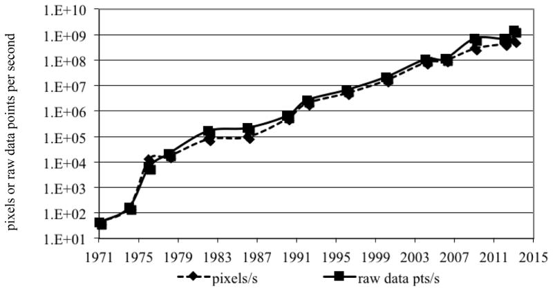
As can be seen in Figure 1, combined with other advances since the development of CT, this led a phenomenal increase in the imaging speed of CT since its introduction in the early 1970’s1. The growth in imaging speed is essentially exponential and has increased by more than seven orders of magnitude during this period of time. This increase in speed along with improvements in low-contrast detectability and image quality have allowed the technique to be much more robust and this, in turn, has enabled CT to become a mainstream in medical care throughout the world. It was judged by primary care physicians to be one of the most important technical innovations in medicine (2).
Figure 1.
Speed of CT since its introduction, measured in raw data points measured per second, or in the number of pixels that the measured raw data is used to reconstruct.
The improvement in image quality and speed, and the robustness and utility of the technique have in turn, increased the clinical utilization of the technology. See, for example (3; 4). Historically, the main drivers for technological improvements have been the physicians’ demand for improved image quality, speed, and new clinical applications. The desire to reduce radiation dose has more recently emerged as an additional technology driver. As a result of the increased utilization, even though the radiation dose per scan has dropped in recent years, the radiation dose burden to the from CT has grown. For example, of the total dose of ionizing radiation dose to the population of the United States in 2006, roughly half was due to natural sources and the other half to man-made sources. CT imaging was responsible for approximately half of the man made radiation dose, 24% of the ionizing radiation dose to the United States population (5). To any individual patient, the benefits from CT far outweigh the risk, but the concern over the population dose has caused dose reduction to become an important technology driver. CT technology development in the coming decade can be expected to be driven by the same forces that have driven the development of CT since its inception: image quality, speed, new and improved applications, and dose reduction.
The rest of this paper will describe the potential improvements in CT due to improvements in the imaging platform itself, in particular, the improvements that can be expected in imaging speed, spatial resolution, and dose efficiency. Improvements that have come about due to the development of advanced image reconstruction algorithms are discussed. New reconstruction methods have, in turn, brought a new problem that needs to be addressed, the need for image quality assessment tools for non-linear imaging systems. Potential new applications are reviewed, followed by a brief discussion of whether the system designs of multiple vendors will converge or diverge and have a range of imaging platforms available for users.
Temporal resolution and imaging speed
Figure 1 shows that the imaging speed of CT since has increased by 9 orders of magnitude in 4 decades. This great increase has been accomplished using two approaches. One is improvement of scan time itself, that is, reducing the time it takes to collect the data for any single slice. The second is increasing the number of slices that are measured in parallel though the use of multi-detector row technology.
Figure 2 shows the minimum scan time (the most critical determinant of this for conventional systems being the rotation speed of the CT Gantry) since the introduction of CT. There was a very rapid reduction in the first decade of the availability of CT, and generally a much slower reduction since around 1980. There are some exceptions that are labeled in figure 2. One is the electron-beam CT (EBCT) system that had unique design specifically to obtain a very short scan time, with cardiac imaging being the targeted applications (6). That system design is no longer commercially available; the market preferred systems with mechanical rotation. There are two recent points that are, roughly a factor of two faster than their contemporaries. These are the dual-source scanners (7) that will be discussed further below.
Figure 2.
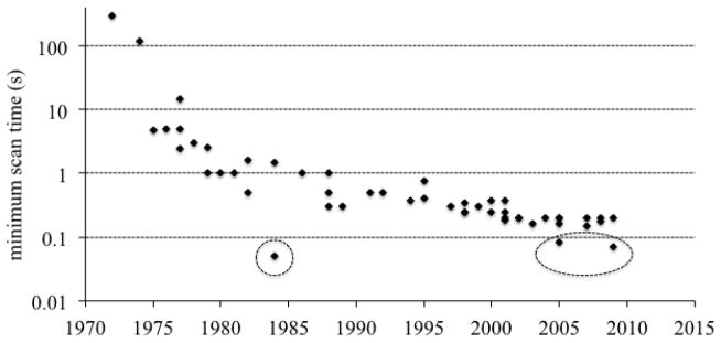
Minimum scan time of CT since its introduction. The outlyer in the early 1980’s was the electron beam CT scanner. The two lower recent points are dual source CT systems that whose minimum scan time is approximately half of the gantry rotation time.
It is logical to ask, then, much faster can CT systems be expected to get in the coming years, if at all? Dual source technology, as seen in Figure 2, can achieve a substantial discrete reduction in the imaging time by having two x-ray sources and two detectors on the gantry operating simultaneously. This reduces the minimum rotation necessary to obtain the needed projections from roughly from 180° to half of that, thereby reducing the minimum scan time for a given gantry rotation speed, by factor of two. Can further speed increases be achieved by mounting more than two imaging chains on the gantry? The answer is almost certainly no. Even to mount two imaging chains on the gantry one of the detectors needed to be smaller to be able to make all the hardware fit. A factor of two is all that can be reasonable expected from multiple-source configurations.
This leaves the question of how much faster can the rotation speed of a gantry be? The main technical limitation on the rotation time of a CT gantry is the centripetal force on the components that are mounted on the rotating frame, especially on the x-ray tube. Figure 3 shows the trend of the g-forces on the CT x-ray tube. There were significant increases since roughly the mid-1990’s. It is an exceptional engineering achievement to have components on the gantry sustain g-forces that are nearly forty times the gravitational pull of the earth. It is also amazing that the trend has not shown any flattening, strongly suggesting that further increases are likely. Since the centripetal force increases as the square of the rotation speed, further increases in the tolerance to g forces will have a decreasing effect on the rotation time. Nonetheless, reductions from the currently shortest rotation time of 0.25 s to 0.2 s or less can be expected in the coming decade.
Figure 3.
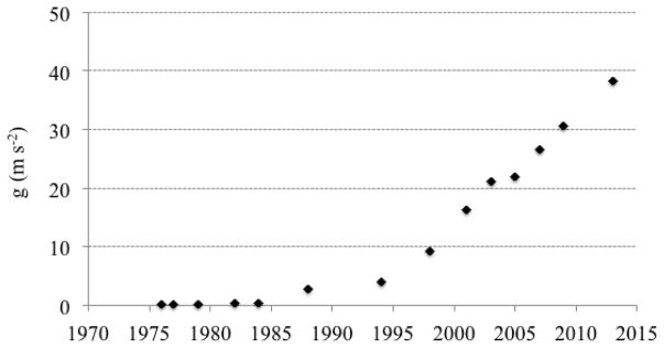
Centripetal acceleration at the location of the x-ray tube. The values are calculated for Siemens CT systems since 1976 but are representative of the field.
The main clinical application that has driven the desire for higher temporal resolution is cardiac imaging. For a review of cardiac CT the reader is referred to (8). When minimum scan times were on the order of the cardiac period or longer, the only way to achieve high temporal resolution was with multi-cycle acquisitions in which the same anatomy is measured during multiple rotations, the ECG is recorded along with the CT raw data, and data are sorted into cardiac phases (9). The residual motion per cardiac phase is reduced and the temporal resolution is improved as more data is acquired, but this approach has disadvantages including long exam times and high radiation dose. As the minimum scan time for CT was reduced to well below one second, simply triggering the scanner at the desired phase of the cardiac cycle became possible. The heart can be imaged at a point in its cycle with relative stasis, and if need-be imaging at multiple phases can be performed to depict cardiac function. However, even with imaging times of the order of 0.1 s there can be enough residual motion of cardiac structures to cause blurring and motion artifacts. Further reduction in imaging time would be helpful, but another way this problem can be addressed is the development of reconstruction algorithms with reduced sensitivity to object motion. Recently developed methods (10; 11) have been able to estimate the motion of the heart as part of the reconstruction process and build in a correction for the residual motion during the data acquisition window. They can produce images with less blurring and artifact. These are important advances and likely to lead to substantial benefits in cardiac imaging applications.
Summarizing this section on temporal resolution, the minimum rotation time of CT systems over the next decade might be reduced from current values of around 0.250 s to 0.15–0.2 s. This would lead to minimum imaging times of around 0.040 s in dual source systems and about 0.075 s in conventional single-source systems. Further improvements in effective temporal resolution for cardiac imaging will be available by the use of reconstruction algorithms that correct for residual motion.
Detector technology
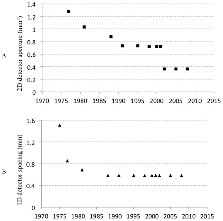
An important determinant of the spatial resolution of a CT scanner is the detector aperture – the spatial resolution of the detector itself. Figure 4A shows a plot of the minimum detector aperture (at position of the patient and corrected) as function of time since the introduction of CT. As with the other parameters discussed above, there has been substantial improvement in the detector aperture over time. Most of this reduction is due to a reduction in the axial or slice direction (i.e., an improvement of the minimum slice thickness). Figure 4B shows a similar plot for the aperture in one dimension, the detector resolution in the in-plane direction. There was a significant improvement in the early years of CT, and then essentially a plateau with no significant improvements of this important technical parameter since the mid-1980’s.
Figure 4.
(A) 2D detector aperture and (B) 1D detector aperture of CT systems. The values are calculated for GE CT systems but are representative of the field.
The reason for this is the detector technology that’s been used in CT since that time. All current commercial systems use scintillator photo diode detectors (Figure 5A). They comprise scintillators that are individually cut and polished, coated with reflectors to prevent crosstalk between cells, and optically coupled to photo diodes. X-rays absorbed in the scintillator produce light that is converted by the photodiode into an electrical signal. The nominal spacing of these detectors is ~ 1 mm, the typical thickness of the reflector is on the order of 100 microns. Since any x-rays incident on the reflectors are lost, the detectors have a geometric efficiency in one dimension of about 90%, and in two-dimensions of about 80%. Construction of higher resolution detectors would require the construction of smaller scintillators, which is difficult by itself, but more importantly, a larger fraction of the surface area of the detector would be covered by reflector, further reducing the geometric efficiency and the dose efficiency of the system. Therefore, the detector aperture of CT systems has been limited by the detector technology that has been use for decades.
Figure 5.
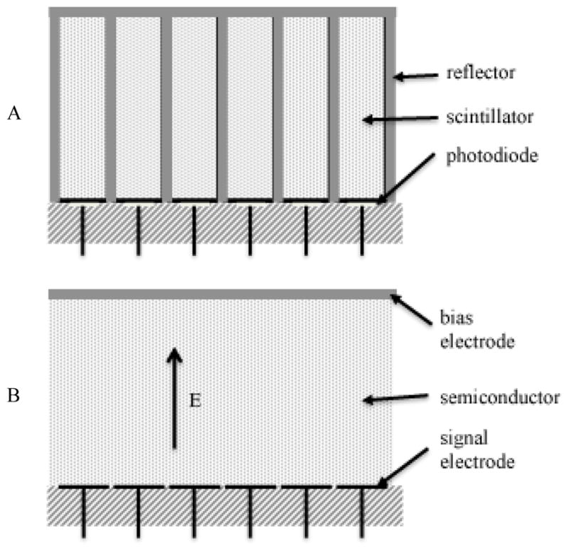
(A) Diagram of scintillator-photodiode detector. The photodiodes are connected to amplifiers and A/D converters. Multi-detector row CT systems had 2D arrays of detector cells. (B) Diagram of direct conversion detector. In photon counting detectors, each signal electrode is connected to a pulse shaping amplifier and one or more discriminators.
Even though it is difficult to improve the aperture and the sampling of CT detectors, it is worth asking what benefits would be obtained if one were able to do so. Obviously, the limiting spatial resolution of the systems would be improved, but interestingly, the detective quantum efficiency (a determinant of the dose efficiency) of the system would be improved substantially, especially at mid to high frequencies (12). The reason for this is that while the finite resolution of the CT detector blurs the signal, the noise in the various detector cells is independent (the noise is “white”). Thus, even though the modulation transfer function (MTF) is attenuated at mid to high spatial frequencies, the noise power spectrum (NPS) is not. The detective quantum efficiency, DQE, which is proportional to MTF2(f)/NPS(f), is significantly reduced at mid to high frequencies. If the MTF of the detector within the desired bandwidth could be increased significantly the DQE would be improved substantially. This has been demonstrated in (12). An example of the type of benefit that would be obtained is shown in Figure 6A-B, which demonstrates that the ability of the system to be able to detect two small signals in close proximity is greatly enhanced by the improvement in sampling of the detector. Figure 6C shows that the accuracy of the CT scanner in these very high-resolution tasks would be significantly improved.
Figure 6.
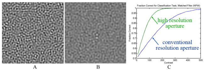
Computer simulation of two small round objects with a center-to-center spacing of two diameters imaged by systems with (A) conventional aperture and (B) high resolution aperture at the same radiation dose, assuming equal x-ray detection efficiency and reconstructed at the resolution limit of the conventional aperture. (C) Performance of a numerical observer to classify whether the object is two disks or one.
Another major limitation of existing detectors is electronic noise, stochastic additive noise that is independent of the measured signal (13). As the detected signal level is reduced, quality of the measurements becomes dominated by electronic noise. The only way to reduce this is to either increase the signal, which requires an increase in dose to the patient, or to reduce the electronic noise level of the system. The dependence of the variance in projection measurements as a function of x-ray fluence is shown in Figure 7. There is a region in which the variance as a function of fluence plotted on a log-log scale has a slope of -1; this is the quantum noise limited region where systems ideally operate. However, when the fluence (or-x-ray signal) is low, either by the desire to reduce radiation dose or when imaging obese patients, the slope of the curve is -2. The system can quickly get into situations where the variance of the measurements can be many times higher than that due to the x-rays alone.
Figure 7.
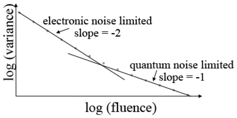
Variance in projection (line integral) measurements due to quantum noise and electronic noise as a function of x-ray fluence. As the x-ray fluence decreases the system can become severely limited by electronic noise.
Detector technologies have been proposed that avoid a number of the limitations of current CT detector systems. Direct conversion photon counting detectors in particular, are diagramed in Figure 5B. With such detectors, each photon creates a number of charge carriers in the semiconductor in proportion to the energy deposited. Crosstalk between adjacent detector channels is prevented by the fact that the charge carriers produced in the semiconductor follow electric field lines, so these detectors do not require reflectors to avoid significant crosstalk. As a result, these types of detectors avoid the geometric inefficiency described previously for the scintillator-photodiode detectors used in current commercial systems, and they can readily achieve much better spatial resolution. If the electronics are designed so that individual photons are detected and counted, the system can avoid the electronic noise problem. A threshold sufficiently higher than the electronic noise floor is defined so that any x-ray photon that produces a signal whose height exceeds the threshold is converted to a digital event; the electronic noise is no issue other than setting a lower limit on the energy of the x-rays that can be detected. The electronics can further be designed to have multiple signal thresholds so that the energy of the x-rays can be used to "bin" the photons into energy intervals. The system then intrinsically has a spectral detector that allows a number of important applications to be easily done (14). Therefore the benefits from these direct conversion photon counting detectors include 100% geometric efficiency, no electronic noise, higher spatial resolution, and spectral imaging capabilities that do not require special protocol changes. In addition, the energy information can be used to optimize the contrast to noise ratio of the image.
Thus, photon-counting technology is a very promising advance in the technical evolution of CT imaging. However, further development and optimization both in hardware and processing algorithms is needed. The main technical challenges come from the count rate capability of the detectors. Current generation photon counting systems are not able handle to the high flux of x-rays incident on the detector. If system operation was limited to the counting rates that detectors can readily handle, the imaging speed of the system would have to slow down in order to still be able to still measure enough x-ray photons. In addition, if the detectors are forced to operate close to their counting rate limits, the spectral information becomes distorted due to pulse pile-up. It therefore can be expected that it will be a few years at least until these detectors are introduced into mainstream CT scanners. Further, one can expect their initial deployment to be in targeted settings rather than in general-purpose systems. The detectors are expensive, so it’s unlikely that very wide cone-beam systems requiring large-area detectors (see below) and with fast imaging speeds will be the first systems into which such detectors are introduced. Rather, it is likely that their initial deployment of these detectors will be on systems that optimized for spatial resolution and dose efficiency rather than imaging speed and coverage.
Volumetric coverage
Even though the ability of CT systems to produce this slices, with thicknesses on the order of a millimeter was introduced in the late 1970’s, they were not used for volumetric coverage because those systems were only able to produce one slice at a time and with slow imaging rates, so the total time required to cover an organ with thin slices and therefore true 3D imaging would have been too long. The development of helical scanning and especially multi-detector row systems (1) changed that, facilitating the acquisition of thin slices for volumetric coverage and allowing CT to become a routine three-dimensional imaging modality.
Figure 8 shows the number of slices acquired per-rotation as a function of time since the introduction of CT. The first systems were able to produce two slices at once. This was dropped in most diagnostic systems in favor of single slice scanners with faster rotation and higher in-plane resolution. This remained the case until the early 1990’s when there was the more ubiquitous introduction of multi-detector row technology, initially with 4 slices, then 8, 16, 32, and so on, with the systems now being available with as many as 320 detector rows.
Figure 8.
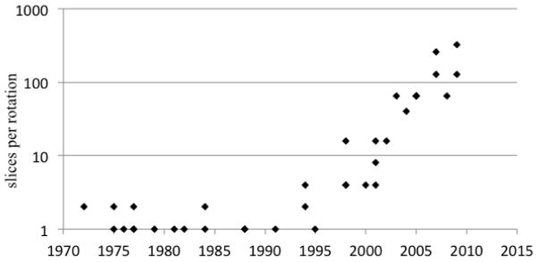
Number of slices per rotation, ignoring the use of reconstruction with less than a full rotation or interpolation in helical reconstruction.
For systems with up to dozens of rows, the main motivation has been fast volumetric coverage with thin slices, largely in a helical scanning protocol. The unique capability of systems with hundreds of rows is wide coverage in a single rotation for dynamic whole organ imaging, especially the brain and the heart. The systems with wide-cone coverage are able to image an entire organ without suffering registration problems between the various slices and also with consistent depiction of the dynamics of contrast agent flow though the volume. This is important for CT perfusion studies and also for the ability to capture the coronary anatomy in a very short time.
These systems are not without disadvantages, however. They are unable to produce accurate reconstructions over the entire volume because of fundamental limitations in the information that is gathered from the object (so-called cone-beam artifacts) and also suffer from a higher rate of detected x-ray scatter and from high cost. One can expect, therefore, that the systems may be important for particular applications, such as whole-organ perfusion and cardiac applications, but are unlikely to become the dominant general-purpose system because of the disadvantages that they entail.
Radiation dose, advanced reconstruction methods, and special purpose systems
Turning now to the issue of radiation dose, it is worth noting the recent progress and further advancements that can reduce the dose to the patient from CT exams. Important dose reductions have already been obtained through the development of optimized imaging protocols, smarter and more efficient x-ray beam collimation, advanced reconstruction algorithms (discussed below), and by control of the x-ray flux illuminating the object.
Initial helical scanners, especially multi-detector row scanners, suffered from so-called “helical over-dosing”. This results from the fact that the anatomy at the very extremes of the illuminated range of the object cannot be reconstructed from helical data because the system collects projections for these regions for a very small angular range. The radiation incident on these regions was wasted. Recently introduced advanced collimators (15) do not illuminate these regions and therefore avoid the dose penalty from this phenomenon.
Control of the illuminated flux on the object is important for several reasons. First, the precision of the reconstructed value in a CT scan depends on the precision of the each of the views. The relationship between the variance and the number of photons in each view (for conventional reconstruction methods) is (16):
where Ni is the number of detected photons that went though a voxel of interest in the ith view and M is the number of views. This inverse relationship means that a few views that have very low x-ray transmission can dominate the variance in the reconstruction. If there are some rays with much better statistics, this does not help this problem. Indeed, excess flux in some views is inefficient from a dose perspective. Several techniques have been developed to control the nonuniformity of Ni across views and therefore improve the dose efficiency of the system. With mA modulation, the x-ray tube power is controlled as a function of view angle and slice location. Systems have so-called “bowtie filters” that define the x-ray intensity as a function of angle within the fan-beam. The combination of the two techniques is able to improve the dose efficiency compared to what would result if the same incident x-ray intensity is used for all rays.
However, even further improvements could be achieved with more flexibility in controlling the x-ray illumination. Inverse Geometry CT is a new system architecture that is able to customize the illuminated flux though the concept of virtual bowtie (17) but is very complex. Recently, dynamic pre-patient attenuators with either piecewise constant (18) or piecewise linear (19) attenuation have been described. Such very fine controls, in a sense, personalize the illumination pattern to the particular patient and application and have been shown to be to improve the dose efficiency by factor of ~2.
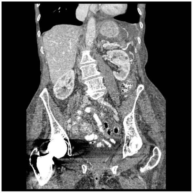
Advanced image reconstruction image reconstruction methods have also been introduced recently. The workhorse algorithm for image reconstruction since the early days of CT is the filtered back-projection (FBP) method. It is very computationally efficient. In addition, if the raw data are perfect the image will be exact. However, if the raw data are not perfect FBP can be inefficient due to the effects of deterministic errors and statistical noise. To overcome this problem, much work has been invested in development of statistical and model based iterative reconstruction (20). Figure 9 shows an example comparison the same data for thin slice, low-dose images reconstructed with FBP and with a model-based iterative method. There is a significant reduction in noise in the iterative reconstruction, with much improvement in the detail that is visible from the data. It is clear that there’s been tremendous advance in the development and use of iterative and statistical reconstruction. These advances are expected to continue, and the algorithms will become even more reliable. The impact of these methods is highest when the data quality is poor, for example with low-dose imaging of large patients. The dose reductions can be significant.
Figure 9.
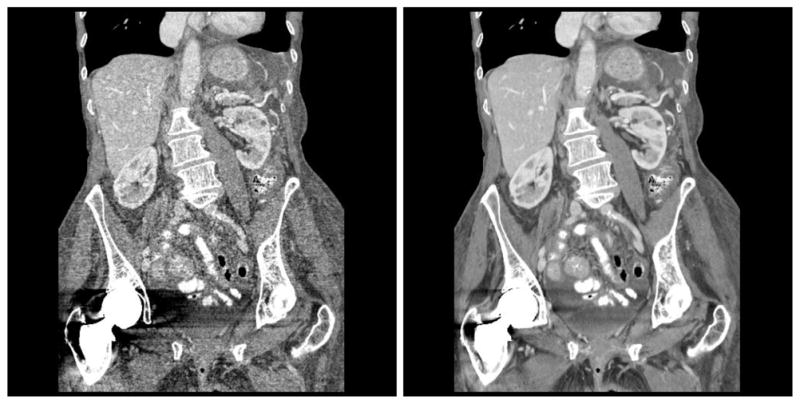
Coronal reformat of images reconstructed with (left) conventional filtered backprojection and (right) model based iterative reconstruction. Images courtesy of J.B. Thibault, R. Senzig, and J. Hsieh.
An important aspect to these reconstructions is that they are non-linear. With linear reconstruction methods such as FBP, the spatial resolution is independent of the noise in the raw data and the image noise is strongly dependent on the x-ray flux (dose). With non-linear methods, the spatial resolution is dose dependent and the image noise depends less strongly on dose. It is important to realize, however, that while the noise level may not vary strongly with dose, the image quality as assessed by radiologists does. Thus, the image noise is no longer a clean surrogate for image quality. Because of the non-linear nature of these systems algorithms, the conventionally used image quality metrics such as modulation transfer function (MTF) and noise power spectrum (NPS) no longer have the theoretical foundation with which to operate. These image quality metrics explicitly assume that the system is linear; with non-linear systems their use is suspect, and new image quality metrics that can be reliably used with such non-linear systems are urgently needed.
The first CT scanners were able to only image the head. However, when whole body CT systems became available, head-only systems essentially disappeared from the marketplace. Even though, in principle, dedicated systems could provide lower cost or higher performance, in practice, general purpose whole body systems were more attractive because they could be used for all applications, they had a larger market, and they were therefore the target for technological investment. That pattern has been changing. Special purpose CT instruments have been produced in recent years, for example, systems specialized for breast CT (21) and for orthopedic CT (22), that are able to image in orientations not possible with general purpose scanners. If these special purpose systems find enough clinical demand, further development is certain.
Summary
Computed tomography technology has made tremendous advances since the technique was introduced in the early 1970’s. The technical improvements have led to excellent and reliable image quality and in turn to its ubiquitous use in clinical medicine. By analyzing the historical trends informed predictions of future directions can be made. Improvements in temporal resolution can be expected, with minimum rotation times of less than 200 milliseconds, scan times of 80 milliseconds for single-source systems and 40 milliseconds for dual source systems, and further immunity from residual motion through the use of reconstruction methods that incorporate residual object motion into the calculation. The use of iterative reconstruction will continue to become more widespread as the algorithms become more robust and the reconstruction times become shorter.
If x-ray detectors with finer apertures and fast photon counting capabilities become available, it is likely that they will be introduced first for targeted deployment. They can be expected to produce substantial improvements in spatial resolution, and also in detective quantum efficiency, especially at mid to high frequencies. Lower radiation dose will be achievable through the use of these higher efficiency detectors and also advanced reconstruction algorithms. It’s unlikely that all of the advances that CT might achieve in the coming decade can be implemented in a single system. Rather, it is most likely that a wide array of systems with different strengths (and weaknesses) will be available, some optimized to maximize dose efficiency, others optimized to minimize the scan time and perhaps still others optimized to have wide volume coverage. Medical centers are therefore likely to have a variety of systems with different capabilities, and these will be used for clinical applications for which those unique capabilities are most important.
Special purpose CT instruments have been produced in recent years, primarily for research use but commercialization has begun. If this trend continues, there will be even more diversity in the CT architectures that are deployed clinically. Each of these is likely to lead to new clinical applications as further refinements occur.
Through all of this, exciting advances in diagnostic computed tomography can be expected.
Acknowledgments
The author receives research support from GE Healthcare, Philips Healthcare, and Samsung Electronics.
Footnotes
The data for the values in Figure 1 and in similar figures below were kindly provided through personal communications by Ami Altman, Thomas Flohr, David Hoffman, Jiang Hsieh, Richard Mather, Raymond Schultz, Robert Senzig, and Michael Silver.
References
- 1.Hsieh J. Computed Tomography: Principles, Design, Artifacts, and Recent Advances. 2. Bellingham, WA: Society of Photo Optical Instrumentation Engineering; 2009. [Google Scholar]
- 2.Fuchs VR, Sox HC., Jr Physicians' views of the relative importance of thirty medical innovations. Health Aff. 2001;20:30–42. doi: 10.1377/hlthaff.20.5.30. [DOI] [PubMed] [Google Scholar]
- 3.Broder J, Fordham L, Warshauer D. Increasing utilization of computed tomography in the pediatric emergency department, 2000–2006. Emergency Radiology. 2007;14:227–32. doi: 10.1007/s10140-007-0618-9. [DOI] [PubMed] [Google Scholar]
- 4.Broder J, Warshauer D. Increasing utilization of computed tomography in the adult emergency department, 2000–2005. Emergency Radiology. 2006;13:25–30. doi: 10.1007/s10140-006-0493-9. [DOI] [PubMed] [Google Scholar]
- 5.160 N. R. N. NCRP Report No. 160, Ionizing Radiation Exposure of the Population of the United States. National Council on Radiation Protection and Measurements; 2009. [Google Scholar]
- 6.Boyd DP, Lipton M. Cardiac computed tomography. Proc IEEE. 1983;71:298–307. [Google Scholar]
- 7.Flohr TG, McCollough CH, Bruder H, Petersilka M, Gruber K, et al. First performance evaluation of a dual-source CT (DSCT) system. Eur Radiol. 2006;16:256–68. doi: 10.1007/s00330-005-2919-2. [DOI] [PubMed] [Google Scholar]
- 8.Halliburton S, Arbab-Zadeh A, De D, Einstein AJ, Gentry R, et al. State-of-the-art in CT hardware and scan modes for cardiovascular CT. J Cardiovasc Comput Tomogr. 2012;6:154–63. doi: 10.1016/j.jcct.2012.04.005. [DOI] [PMC free article] [PubMed] [Google Scholar]
- 9.Kachelriess M, Kalender WA. ECG-correlated image reconstruction from subsecond spiral computed tomography scans of the heart. Med Phys. 1998;25:2417–31. doi: 10.1118/1.598453. [DOI] [PubMed] [Google Scholar]
- 10.Leipsic J, Labounty TM, Hague CJ, Mancini GBJ, O’Brien JM, et al. Effect of a novel vendor-specific motion-correction algorithm on image quality and diagnostic accuracy in persons undergoing coronary CT angiography without rate-control medications. J Cardiovasc Comput Tomogr. 2012;6:164–71. doi: 10.1016/j.jcct.2012.04.004. [DOI] [PubMed] [Google Scholar]
- 11.Rohkohl C, Bruder H, Stierstorfer K, Flohr T. Improving best-phase image quality in cardiac CT by motion correction with MAM optimization. Med Phys. 2013;40:031901 1–15. doi: 10.1118/1.4789486. [DOI] [PubMed] [Google Scholar]
- 12.Baek J, Pineda A, Pelc NJ. To bin or not to bin? The effect of CT system limiting resolution on noise and detectability. Phys Med Biol. 2013;58:1433–46. doi: 10.1088/0031-9155/58/5/1433. [DOI] [PubMed] [Google Scholar]
- 13.Pelc NJ. Statistical aspects of digital x-ray imaging. In: Fullerton GDea., editor. Electronic Imaging in Medicine. New York: Am. Inst. Phys; 1984. pp. 320–31. [Google Scholar]
- 14.Alvarez RE, Macovski A. Energy-selective reconstructions in X-ray computerised tomography. Phys Med Biol. 1976;21:733–44. doi: 10.1088/0031-9155/21/5/002. [DOI] [PubMed] [Google Scholar]
- 15.Christner JA, Zavaletta VA, Eusemann CD, Walz-Flannigan AI, McCollough CH. Dose reduction in helical CT: dynamically adjustable z-axis X-ray beam collimation. American Journal of Roentgenology. 2010;194:W49. doi: 10.2214/AJR.09.2878. [DOI] [PubMed] [Google Scholar]
- 16.Chesler DA, Riederer SJ, Pelc NJ. Noise due to photon counting statistics in computed X-ray tomography. J Comput Assist Tomogr. 1977;1:64–74. doi: 10.1097/00004728-197701000-00009. [DOI] [PubMed] [Google Scholar]
- 17.De Man B, Basu S, Bequé D, Claus B, Edic P, et al. Multi-source inverse geometry CT : a new system concept for X-ray computed tomography. Proc. SPIE Medical Imaging Conference; San Diego, CA. 2007. [Google Scholar]
- 18.Szczykutowicz TP, Mistretta CA. Design of a digital beam attenuation system for computed tomography. Part II. Performance study and initial results. Med Phys. 2013;40:021906-1-9. doi: 10.1118/1.4773880. [DOI] [PMC free article] [PubMed] [Google Scholar]
- 19.Hsieh SS, Pelc NJ. The feasibility of a piecewise-linear dynamic bowtie filter. Med Phys. 2013;40:031910-1-12. doi: 10.1118/1.4789630. [DOI] [PMC free article] [PubMed] [Google Scholar]
- 20.Thibault JB, Sauer KD, Bouman CA, Hsieh J. A three-dimensional statistical approach to improved image quality for multislice helical CT. Med Phys. 2007;34:4526–44. doi: 10.1118/1.2789499. [DOI] [PubMed] [Google Scholar]
- 21.Boone JM, Nelson TR, Lindfors KK, Seibert JA. Dedicated Breast CT: Radiation Dose and Image Quality Evaluation. Radiology. 2001;221:657–67. doi: 10.1148/radiol.2213010334. [DOI] [PubMed] [Google Scholar]
- 22.Zbijewski W, Jean PD, Prakash P, Ding Y, Stayman JW, et al. A dedicated cone-beam CT system for musculoskeletal extremities imaging: design, optimization, and initial performance characterization. Med Phys. 2011;38:4700–13. doi: 10.1118/1.3611039. [DOI] [PMC free article] [PubMed] [Google Scholar]


