Abstract
The objective of the study is to examine the variation in doses to, Bladder, pelvic wall and Rectal Points when a patient is simulated in Supine (S Position) and Lithotomy M shaped positions (LM Position), respectively as part of Intracavitary Brachytherapy in Cervical Cancer patients. Patients (n = 19) were simulated and orthogonal images were taken in S Position and LM Positions on a physical simulator. Digital orthogonal X-ray images were transferred to Brachyvision Treatment Planning System via Dicom to generate treatment plans. Radio opaque dye of 7 ml was injected into the Foley bulb for identification and digitization of International Commission on Radiological Units and Measurements (ICRU) Bladder point. Pelvic side wall points were marked in accordance with ICRU 38 recommendations. A Rectal tube containing dummy source marker wire was used to identify Rectal Point. Students’t-test was used to analyze the results. Doses in LM Position were lower and statistically significant when compared to S Position for ICRU Bladder Point, pelvic walls and Rectal Point. It was observed that movement of applicator could be the reason for the variations in doses between the two positions. Bladder, pelvic wall and rectal points systematically registered lower doses in LM Position as compared to S Position.
Keywords: Bladder, lithotomy, rectum, supine
Introduction
Cancer of the Cervix is preventable, yet approximately 493,100 new cases and more than 273,000 deaths occur each year among women worldwide.[1] Cancer, known medically as a malignant neoplasm, is a broad group of various diseases, all involving unregulated cell growth. In cancer, cells divide and grow uncontrollably, forming malignant tumors, and invade nearby parts of the body. The cancer may also spread to more distant parts of the body through the lymphatic system or bloodstream. Among females the most common cancer sites are Cervix and Breast. Carcinoma of the cervix is radiosensitive and radiation is used for all stages of cancer and where surgery is not possible. Cancer of the uterine cervix has a high incidence rate among women in India. There are approximately 130,000 new cases of cervical cancer in India per year and the disease is reported to be responsible for almost 20 percent of all female deaths.[1] Most of the radical cases are treated by combination of External beam therapy and Brachytherapy.
Low-Dose-Rate (LDR) brachytherapy has been clinically proved in controlling the tumor with acceptable late morbidity.[2,3,4,5,6,7] High-Dose-Rate (HDR) brachytherapy overcomes the disadvantages of LDR brachytherapy with the added advantages of patient throughput, reduced treatment time and flexibility in dose optimization. Although the dose is delivered at a higher rate than in LDR brachytherapy, the possible late effects can be reduced by adopting low fraction size and multiple fractions with adequate time gap between fractions. All fractions require careful individualized planning due to the geometrical variation of applicators arising from the differences in the anatomy of the patient, variations in packing and position of the patient, keeping the rectal and bladder doses within the acceptable limits.[8,9,10,11,12,13,14,15,16] The applicator, inserted into the patients’ uterine canal and vaginal cavity varies with the anatomical position of the patient. Due to this there is a variation in doses to various anatomical points. Orthogonal film based planning is the standard practice recommended by the American Brachytherapy Society[17] and this is being followed in most of the centers in India.
Materials and Methods
Our center treats nearly 50 patients per week with intracavitary radiation for gynecological malignancies which includes cervical cancer, vagina cancer and cancer of the vault, along with external beam radiation therapy. In this study, number of patients was limited to nineteen due to workload. Supine position (S Position) [Figure 1] is the standard position adopted in this institute to generate and deliver treatment plans. In the present study another position, Lithotomy M shape Position (LM Position) [Figure 2], was added to make a comparison study. Sometimes patients feel more comfortable in LM Position. This study was done adopting LM Position along with the standard S Position. Our center does not practice with applicator stabilizer.
Figure 1.

Patient in Supine Position
Figure 2.

Patient in Lithotomy M Shape Position
Nineteen patients with Carcinoma of the Cervix of grade II and III, aged between 30 to 60 years were selected for this study. Two plans for each patient in two anatomical positions were created by treating each plan as independent of the other. All patients were imaged simultaneously in two positions, S Position and LM Position, on Acuity physical simulator (Varian, Palo Alto, CA, USA) to get orthogonal digital X-ray images [Figures 3 and 4] at gantry angles 0° and 90° after insertion of Henschke applicator (Mick Radio-Nuclear Instruments, Inc., NY, USA) and to confirm the adequacy of position and orientation of the applicator. After imaging, patient was shifted to HDR brachytherapy (Varisource iX, Palo Alto, CA, USA) room for treatment, which is not an integral part of operation theatre, and digital images [Figures 3 and 4] were sent via Dicom to Brachyvision Treatment Planning System (TPS) Version 7.3 (Varian, Palo Alto, CA, USA) through Varian ARIA (Varian, Palo Alto, CA, USA) network.
Figure 3.
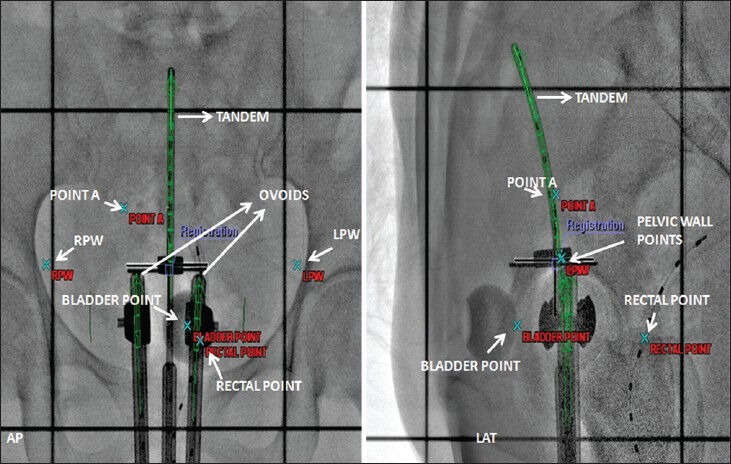
Orthogonal digital X- ray image in Supine position
Figure 4.
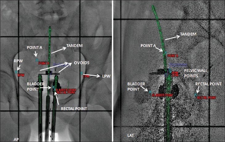
Orthogonal digital X- ray image in Lithotomy M Shape position
Henschke applicator with different tandem lengths and ovoid diameters were employed depending on the patients’ anatomy. Tandem length varies between 4 to 6 cm and ovoids diameter varies from 2-3 cm. Doses ranging from 600 cGy-700 cGy were prescribed to Point A. Brachyvision TPS was used to generate treatment plans. Dose was optimized to Point A and to reference lines placed at 0.5 cm apart from the surface of ovoids. The dose distribution [Figures 5 and 6] and source loading pattern was the same for both the positions. Both the plans were generated with first time insertion of applicator in either position.
Figure 5.
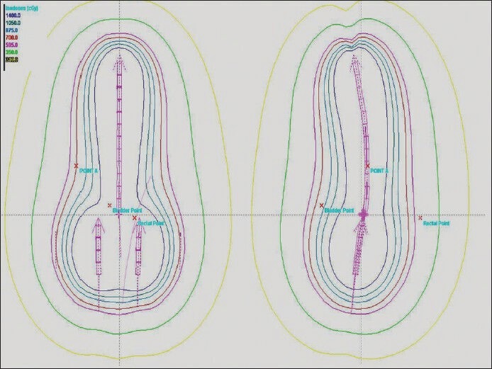
Dose distribution in Supine position
Figure 6.
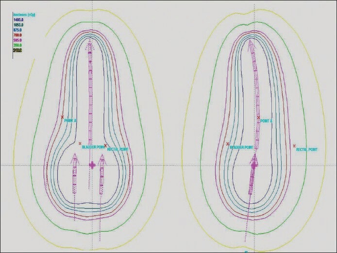
Dose distribution in Lithotomy M Shape position
Dose reference points, Bladder, Pelvic wall and Rectal Points were identified for analysis. The ICRU Bladder and pelvic wall points were identified according to ICRU 38[20] recommendations. Radio opaque dye, Omnipaque (GE Healthcare, UK) of 7cc volume having a density of 350 mg I/ml was injected to inflate the Foley bulb to identify bladder point. It was located at the centre of Foley bulb on AP radiogram and on the line, passing through the centre of bulb, at the posterior surface of the balloon on LT LAT radiogram. The pelvic wall reference points, Right Pelvic Wall (RPW) and Left Pelvic Wall (LPW), can be visualized on AP and LAT radiogram. On an AP radiogram, the pelvic wall reference point is intersected by the following two lines: A horizontal line tangential to the highest point of the acetabulum, a vertical line tangential to the inner aspect of the acetabulum. On a lateral radiogram, the highest points of the right and left acetabulum, in the cranio-caudal direction, are joined and the lateral projection of the pelvic-wall reference points are located at the mid-distance of these points. A Rectal tube containing dummy source marker wire was used to identify the rectal point. It was identified at the intersection of rectal marker and a line joining the centers of the right and left femoral heads on Anterior Posterior (AP) radiogram and on the rectal marker wire at the same level in the Left Lateral (LT LAT) radiogram. Student’s t-test was used to analyze the results.
Results
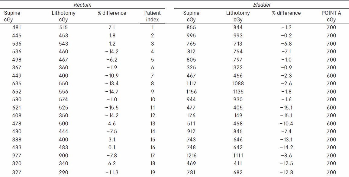
Considerable differences occurred between the doses at the ICRU Bladder point when measured in Supine position and Lithotomy M positions [Table 1]. Results were expressed as a percentage of S Position. The range of dose differences was large with a minimum of −0.15% and a maximum −15.15% with a mean of −7.0% (P = 0.00001). Four of nineteen patients exhibited difference of over −5% and in seven of them the difference amounted to more than −10%.
Table 1.
Ranking indicators of a few medical physics related journals for 2012
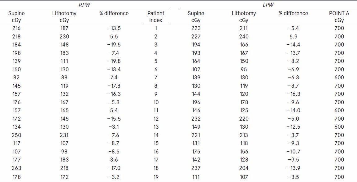
Pelvic wall points registered lower doses in lithotomy [Table 2]. For RPW the range of dose differences from 7.4% to −19.8% and mean of −8.1% (P = 0.0004) was observed. Similar results were observed for LPW with the dose difference ranging from 5.9% to −16.3% with a mean dose of −8.7% (P = 0.00003).
Table 2.
Ranking indicators of a few medical physics related journals for 2012
Rectal point dose was analyzed and observed that the LM Position registered, a mean dose of −5.0% (P = 0.0043) ranging from 7.1% to −15.5% as compared to Supine position [Table 1]. Three patients out of 12 exhibited differences ranging from −5% to −10% and six of them registered more than −10%.
LM Position registered systematically lower doses compared to S Position for bladder, pelvic wall and rectal Points. The mean difference of −7.0% for ICRU bladder, −8.1% and −8.7% for right and left pelvic wall points and −5.0% for rectal point cannot be explained by inaccuracies in TPS dose measurements, but suggests a true difference between doses in two positions.
Discussion
In the present study with nineteen patients, two plans for each patient corresponding to S and LM positions were created. Applicator is a rigid device, made of stainless steel. It is inserted into the patients’ vaginal and uterine cavities, with sufficient Gauge packing around applicator. Gauge pack serves two purposes; it pushes the rectum and bladder away from the applicator and produces enough immobilization to the applicator in situ. Gauze packing is one of the factors affecting the dose to rectum and bladder.[8] In addition to packing the other factor is the position of the patient.[18,19] Hoskin PJ[22]et al., discussed the influence of applicator angle on Dosimetry in vaginal vault brachytherapy. In S Position which is a normal resting position the soft tissues in the pelvis are relaxed. However the change in patients’ position to LM Position, results in the exertion of pressure by the lateral tissues of pelvis which leads to spatial rearrangement of Rectum, Bladder and Applicator. These movements are the reason for the observed variation in doses to Rectum and Bladder. It is observed that applicator moved on an average by 0.35 cm inferiorly in LM position compared to supine position with respect to rectal point which is in turn related to fixed bony landmark.
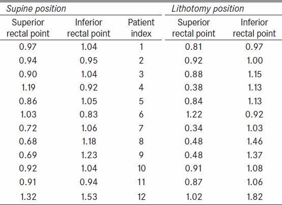
It is the reason to observe lower doses at defined rectal point but not the entire rectal wall. However the same is also the reason for the increase in dose to rectal point as it depends on relative position of rectal point and ovoids. Doses at two other points, superior rectal (SRP) and inferior rectal point (IRP), on the rectal marker at 1cm in either direction from the defined rectal point were also recorded [Table 3] and expressed as ratio of rectal point dose in both positions, S Position and LM Position. It was observed that the doses at superior rectal point are relatively less as compared to doses at inferior rectal point for many patients in LM Position. We also recoded dose at superior and inferior points of Foley bulb with respect to bladder point dose. In S Position, the average ratio with bladder point dose for superior point is 0.59 and for inferior point is 0.54. Where as in LM positions the ratios are 0.58 and 0.62 respectively.
Table 3.
Ranking indicators of a few medical physics related journals for 2012
The dose [Figure 7] to ICRU Bladder point in LM Position shows considerable reduction. This is due to the compression of pelvic tissues leading to the movement of Henschke applicator creating a different geometry compared to S Position. Dose results [Figures 8 and 9] for pelvic wall showed that the applicator moved away posteriorly yielding a lower dose contribution from the ovoid and tandem sources. Dose to Rectal point [Figure 10] was analyzed and observed that the LM Position registered lower dose as compared to S Position. Also the applicator assembly seems to move inferiorly in LM Position. This leads to a substantial reduction in dose contribution from ovoid sources to Rectal Point.
Figure 7.
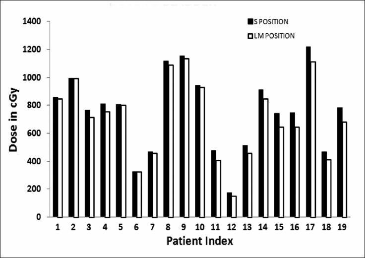
Dose to bladder point in two positions
Figure 8.
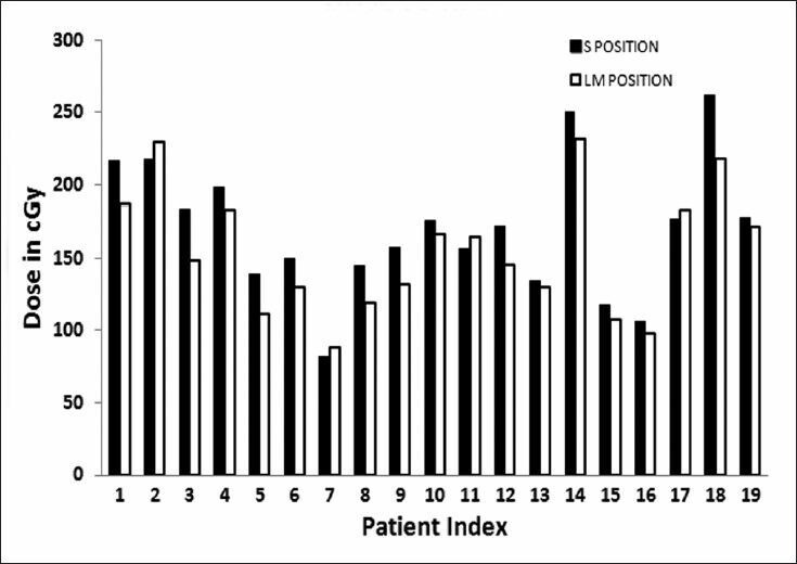
Dose to right pelvic wall point in two positions
Figure 9.
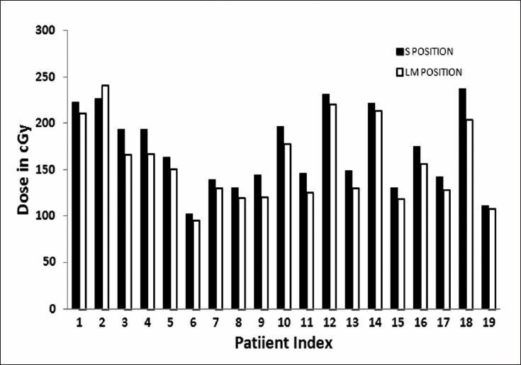
Dose to left pelvic wall point in two positions
Figure 10.
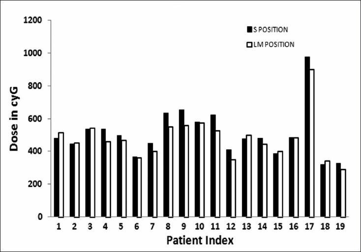
Dose to rectal point in two positions
When we searched literature we could find only two studies similar to the present study. Joelsson et al.,[18] used a Siemens gammameter employing small calcium sulphide solid state dosimeter to record dose rates with a probable error of ±10%. Differences in dose rates were reported between measurements in lithotomy and supine positions as percentages of values obtained with the patient in lithotomy position. The range of differences was large and the limits registered were −14% and +65%. The mean difference in dose rates at the posterior wall of the urinary bladder between the measurements in lithotomy and supine positions amounted to +12% indicating that bladder received higher dose in supine position. And the present study estimates an average 7% higher dose to bladder in supine position. The mean difference in dose rates at the anterior wall of the rectum, between measurements in lithotomy and supine positions, was −3%. This is in close agreement with our study, estimating a mean difference in dose as −5%. A corresponding difference between the mean values of the dose rates at the anterior wall of the rectum in supine and lithotomy positions was not observed to a degree as observed with bladder. The range of differences was about the same as in the bladder measurements, with a lowest value of −47% and a highest value of +34%. In the study by Joelsson et al.,[18] Radium sources were preloaded and the geometry of applicator, though different from the present study, gives an estimate of variation of doses due to change in patients position. In yet another study Yun HG and Shin KC[23] estimated the distance of bladder and rectal points from cervical os in supine and lithotomy positions. They concluded that the average dose to rectum is lower in lithotomy position and the average dose to bladder is lower in supine position. They used ICRU 38 dose reference points with modification in their study.
In our study we have chosen a modified rectal point linking it to the relatively rigid bony landmarks i.e., at the intersection of rectal marker and the line joining the centers of the right and left femoral heads on AP radiogram and on the rectal marker wire at the same level in the LT LAT radiogram. This makes it easy to identify the rectal point at the same level in both anatomical positions. A one to one dose analysis of each patient in both anatomical positions shows that about one third of nineteen patients exhibited relatively higher doses to rectum and lower doses to bladder in LM position. The dose differences range from 0.14% to 7% for rectum and −0.15% - −14.2% (for Patient no 16 in [Table 1]) for bladder. This shows that the increase in dose to rectum is compensated by the reduction of dose to bladder. All the above mentioned studies did conclude that the average dose to the selected population in case of rectum is lower in lithotomy position. Nevertheless it would be interesting to study large population. As brachytherapy procedure takes longer time, immobilization devices are required in Lithotomy Position to reproduce the patient geometry as well as to provide convenience for the patient from imaging to treatment delivery.
Conclusion
This paper presents the current study of positional dependence of dose to ICRU bladder, pelvic wall reference points and defined rectal point. It showed that the plans created in Lithotomy Position registered lower doses.
The decision of choosing the anatomical position i.e., either Supine Position or Lithotomy M position, for treatment planning and delivery can be taken based on proper analysis of comfort to patient and more importantly the doses to organs at risk. With regard to rectum the analysis of doses showed that in most of the cases, Lithotomy Position can give results equally good or better than in Supine position. Dose variation in bladder and rectum can be estimated in both the positions and the position that gives optimum doses can be chosen for the subsequent fractions. Even so interesting would it be to analyze and explore in detail the doses to organs at risk in 3D based planning.
Footnotes
Source of Support: Nil
Conflict of Interest: None declared.
References
- 1.Ferlay J, Bray F, Pisani P, Parkin DM. IARC Cancer Base No. 5. version 2.0. Lyon: IARC Press; 2004. GLOBOCAN 2002: Cancer Incidence, Mortality and Prevalence Worldwide. [Google Scholar]
- 2.Stitt JA, Fowler JF, Thomadsen BR, Buchler DA, Paliwal BP, Kinsella TJ. High dose rate intracavitary brachytherapy for carcinoma of the cervix: The Madison System: I. Clinical and radiobiological considerations. Int J Radiat Oncol Biol Phys. 1992;24:335–48. doi: 10.1016/0360-3016(92)90690-j. [DOI] [PubMed] [Google Scholar]
- 3.Brenner DJ, Hall EJ. Fractionated high dose rate versus low dose rate regimens for Intracavitary brachytherapy of the cervix. Br J Radiol. 1991;64:133–41. doi: 10.1259/0007-1285-64-758-133. [DOI] [PubMed] [Google Scholar]
- 4.Eifel PJ. High-dose-rate brachytherapy for carcinoma of the cervix: High tech or high risk? Int J Radiat Oncol Biol Phys. 1992;24:383–6. doi: 10.1016/0360-3016(92)90696-f. [DOI] [PubMed] [Google Scholar]
- 5.Dale RG. The application of the linear-quadratic dose-effect equation to fractionated and protracted radiotherapy. Br J Radiol. 1985;58:515–28. doi: 10.1259/0007-1285-58-690-515. [DOI] [PubMed] [Google Scholar]
- 6.Hsu WL, Wu CJ, Jen YM, Yen SH, Lin KT, Ger LP, et al. Twice-per-day fractionated high versus continuous low dose rate Intracavitary therapy in the radical treatment of cervical cancer: A nonrandomized comparison of treatment results. Int J Radiat Oncol Biol Phys. 1995;32:1425–31. doi: 10.1016/0360-3016(94)00484-3. [DOI] [PubMed] [Google Scholar]
- 7.Thomadsen BR, Shahabi S, Stitt JA, Buchler DA, Fowler JF, Paliwal BR, et al. High dose rate intracavitary brachytherapy for carcinoma of the cervix: The Madison System: II, Procedural and physical considerations. Int J Radiat Oncol Biol Phys. 1992;24:349–57. doi: 10.1016/0360-3016(92)90691-a. [DOI] [PubMed] [Google Scholar]
- 8.Garipagaoglu N, Tuncel NG, Dalmaz MG, Gulkesen H, Toy A, Kizildag AU, et al. Changes in applicator positions and dose distribution between high dose rate brachytherapy fractions in cervix carcinoma patients receiving definitive radiotherapy. Br J Radiol. 2006;79:504–09. doi: 10.1259/bjr/33762931. [DOI] [PubMed] [Google Scholar]
- 9.Hoskin PJ, Cook M, Bouscale D, Cansdale J. Changes in applicator position with fractionated high dose rate gynecological brachytherapy. Radiother Oncol. 1996;40:59–62. doi: 10.1016/0167-8140(96)01746-x. [DOI] [PubMed] [Google Scholar]
- 10.Kim RY, Meyer JT, Plott WE, Spencer SA, Meredith RF, Jennelle RL, et al. Major geometric variations between multiple high-dose-rate applications of brachytherapy in cancer of cervix: Frequency and types of variation. Radiology. 1995;195:419–22. doi: 10.1148/radiology.195.2.7724760. [DOI] [PubMed] [Google Scholar]
- 11.Bahena JH, Martinez A, Yan D, Mele E, Edmunson G, Brown D, et al. Spatial reproducibility of the ring and tandem high-dose rate cervix applicator. Int J Radiat Oncol Biol Phys. 1998;41:13–9. doi: 10.1016/s0360-3016(98)00026-1. [DOI] [PubMed] [Google Scholar]
- 12.Hellebust TP, Dale E, Skjonsberg A, Olsen DR. Inter fraction variations in rectum and bladder volumes and dose distributions during high dose rate brachytherapy treatment of the uterine cervix investigated by repetitive CT examinations. Radiother Oncol. 2001;60:273–80. doi: 10.1016/s0167-8140(01)00386-3. [DOI] [PubMed] [Google Scholar]
- 13.Datta NR, Kumar S, Das KJ, Pandey CM, Halder S, Ayyagari S. Variations of intracavitary applicator geometry during multiple HDR brachytherapy insertions in carcinoma cervix and its influence on reporting as per ICRU report 38. Radiother Oncol. 2001;60:15–24. doi: 10.1016/s0167-8140(01)00352-8. [DOI] [PubMed] [Google Scholar]
- 14.Ljunggren L, Wyman D, Harley L. An assessment of calculated doses in Intracavitary gynecologic radiotherapy. Med Dosim. 1987;12:15–27. [Google Scholar]
- 15.Grigsby PW, Georgiou A, Williamson JF, Perez CA. Anatomic variation of gynecologic brachytherapy Prescription points. Int J Radiat Oncol Biol Phys. 1993;27:725–9. doi: 10.1016/0360-3016(93)90402-h. [DOI] [PubMed] [Google Scholar]
- 16.Saarnak AE, Boersma M, van Bunningen BN, Wolterink R, Steggerda MJ. Inter-observer variation in delineation of bladder and rectum contours for brachytherapy of cervical cancer. Radiother Oncol. 2000;56:37–42. doi: 10.1016/s0167-8140(00)00185-7. [DOI] [PubMed] [Google Scholar]
- 17.Nag S, Erickson B, Thomadsen B, Orton C, Deanes JD, Petereit D. The American brachytherapy society recommendations for High Dose Rate brachytherapy for carcinoma of the cervix. Int J Radiat Oncol Biol Phy. 2000;48:201–11. doi: 10.1016/s0360-3016(00)00497-1. [DOI] [PubMed] [Google Scholar]
- 18.Joelsson I, Bäckström A. Dose rate measurements in bladder and rectum. Intracavitary radiation of carcinoma of the uterine cervix. Acta Radiol Ther Phys Biol. 1969;8:343–59. doi: 10.3109/02841866909134464. [DOI] [PubMed] [Google Scholar]
- 19.Joelsson I, Bäckström A. Applicators for remote afterloadjng technique for optimum pelvic dose distribution in carcinoma of the uterine cervix. Acta Radiol Ther Phys Biol. 1970;9:233–46. doi: 10.3109/02841867009129102. [DOI] [PubMed] [Google Scholar]
- 20.Dose and Volume Specification for Reporting Intracavitary Therapy in Gynecology. ICRU Report No 38. 1985 [Google Scholar]
- 21.Basu B, Basu S, Chakraborti B, Ghorai S, Gupta P, Ghosh S, et al. A comparison of dose distribution from Manchester style and Fletcher-style intracavitary brachytherapy applicator systems in cervical cancer. J Contemp Brachytherapy. 2012;4:213–8. doi: 10.5114/jcb.2012.32555. [DOI] [PMC free article] [PubMed] [Google Scholar]
- 22.Hoskin PJ, Bownes P, Summers A. The influence of applicator angle on dosimetry in vaginal vault brachytherapy. Br J Radiol. 2002;75:234–7. doi: 10.1259/bjr.75.891.750234. [DOI] [PubMed] [Google Scholar]
- 23.Yun HG, Shin KC. Study of patients position to reduce late complications in high dose rate intracavitary radiation of the uterine cervix cancer. J Korean Soc Ther Radiol Oncol. 1998;16:477–84. [Google Scholar]


