Abstract
Background and Aims
Cables composed of long, non-lignified fibre cells enclosed in a cover of much shorter thin-walled, crystal-containing cells traverse the air chambers (lacunae) in leaves of the taller species of Typha. The non-lignified fibre cables are anchored in diaphragms composed of stellate cells of aerenchyma tissue that segment the long air chambers into smaller compartments. Although the fibre cables are easily observed and can be pulled free from the porous-to-air diaphragms, their structure and function have been ignored or misinterpreted.
Methods
Leaves of various species of Typha were dissected and fibre cables were pulled free and observed with a microscope using bright-field and polarizing optics. Maximal tensile strength of freshly removed cables was measured by hanging weights from fibre cables, and Instron analysis was used to produce curves of load versus extension until cables broke.
Key Results and Conclusions
Polarized light microscopy revealed that the cellulose microfibrils that make up the walls of the cable fibres are oriented parallel to the long axis of the fibres. This orientation ensures that the fibre cables are mechanically stiff and strong under tension. Accordingly, the measured stiffness and tensile strength of the fibre cables were in the gigapascal range. In combination with the dorsal and ventral leaf surfaces and partitions that contain lignified fibre bundles and vascular strands that are strong in compression, the very fine fibre cables that are strong under tension form a tensegrity structure. The tensegrity structure creates multiple load paths through which stresses are redistributed throughout the 1–3 m tall upright leaves of Typha angustifolia, T. latifolia, T. × glauca, T. domingensis and T. shuttleworthii. The length of the fibre cables relative to the length of the leaf blades is reduced in the last-formed leaves of flowering individuals. Fibre cables are absent in the shorter leaves of Typha minima and, if present, only extend for a few centimetres from the sheath into the leaf blade of Typha laxmannii. The advantage of the structure of the Typha leaf blade, which enables stiffness to give way to flexibility under windy conditions, is discussed for both vegetative and flowering plants.
Keywords: Biomechanics, cattail, cellulose microfibrils, fibre cables, fibre cells, hierarchical structure, pleochroism, polarized light microscopy, tensegrity, Typha
INTRODUCTION
The structure of Typha leaves has been described by Meyer (1933), Solereder and Meyer (1933), Teale (1949), Kaul (1974), Rowlatt and Morshead (1992) and McManus et al. (2002). The leaf blade of Typha, which functions to intercept photosynthetically active radiation, is produced by an intercalary meristem at its base. Some of the internal tissue of this photosynthetic organ breaks down to form lacunae that allow oxygen to flow through the entire length of the leaf to the submerged parts of the plant and carbon dioxide to flow from the submerged parts to the photosynthetic parts (Constable et al., 1992; Constable and Longstreth, 1994). The remaining tissue includes the thick dorsal and ventral tissue, the thick partitions that separate the dorsal and ventral tissue, the thin diaphragms made of two or three layers of thin-walled stellate cells of aerenchyma tissue, and the thin fibre cables that traverse the diaphragms and air lacunae.
Although fibre cables that traverse the air chambers (lacunae) are easily observed and can be pulled free from the porous-to-air diaphragms to which they are anchored, their structure and function have been ignored or misinterpreted. Kaul (1974) interpreted them to be ‘vertical ducts’ and Rowlatt and Morshead (1992) referred to ‘longitudinal fibres’ in ‘the lacunae as well as elsewhere’. Here we used light and scanning electron microscopy to visualize the structure of the fibre cables and suggest that the fibre cables are unique non-lignified structural elements that contribute to a four-level hierarchy to form a tensegrity structure that ensures the mechanical stability of the leaf. To characterize the mechanical properties of the cables, break loads, maximal tensile strength and stiffness (Young's modulus) of fibre cables were determined.
MATERIALS AND METHODS
Typha is a cosmopolitan genus of plants that can be found in almost any wet habitat almost anywhere in the world. Leaves of Typha angustifolia, T. latifolia, T. × glauca (hybrids between T. angustifolia and T. latifolia; Fassett and Calhoun, 1952) were collected in England and the USA. Leaves of T. domingensis were collected in Israel. Typha minima was obtained from a commercial nursery (Totalily, Spencer, New York) and a living plant of T. laxmannii from Bill Dress of the Bailey Hortorium, Cornell University. Leaves of T. laxmannii and T. shuttleworthii from herbarium specimens at the Bailey Hortorium at Cornell University were also examined.
Leaves of various species of Typha were dissected and observed with a stereo microscope and the length of the fibre cables that traverse the longitudinal air chambers of the leaf blade was noted. Leaf blade measurements were from the point of highest attachment of the basal leaf sheath to the leaf blade. Fibre cables were pulled free of the diaphragms and were observed with an Olympus BH-2 microscope using bright-field and polarizing optics. The cables were treated with phloroglucinol–HCl (McLean and Ivimey Cook, 1941) and observed with bright-field microscopy to test for the presence of lignin. Intact or squashed cables were treated with I2KI or chloroiodide of zinc (McLean and Ivimey Cook, 1941) to introduce pleochroism to determine the orientation of the cellulose microfibrils in the fibre cables and fibre cells, respectively, using a polarizing light microscope without the analyser. The orientation of the cellulose microfibrils was also determined in intact and squashed cables with a polarizing light microscope equipped with crossed polars and a full-wave plate by observing additive or subtractive colours (Naegeli and Schwendener, 1892; Wayne, 2009a). The fibres were macerated in Mangin's maceration solution [3:1 (v/v) EtOH:HCl followed by a water rinse and then placed in 10 % ammonium hydroxide] or Jeffrey's maceration solution [1:1 (v/v) 10 % chromic acid:10 % nitric acid] at 40 °C for 3–5 h followed by a water rinse to separate the fibre cells (McLean and Ivimey Cook, 1941).
Digital images were captured as TIFF files with a 5 MP digital camera (AmScope, Irvine, CA, USA) using the ToupView (Ver. x86, 3·7.939) image processing program. Cell lengths were calibrated with a stage micrometer and measured with ImageJ (http://rsb.info.nih.gov/ij/), which is available free from the National Institutes of Health, USA. ImageJ was also used to add calibrated scale bars to the images. Scanning electron microscopy was performed on samples that had been dehydrated with an ethanol series and then critical-point dried.
The maximum tensile strength of freshly removed cables was measured by hanging weights from fibre cables with Scotch tape and finding the hanging weight necessary to break the cables. The maximum tensile strength (Tmax) at failure was determined with the following formula:
 |
where Fmax is the maximum force added to a cable and A is the cross-sectional area of that cable. This test has the advantage that it can be applied in the field or in any teaching or research laboratory that does not have an Instron.
To perform the Instron analysis, 6-cm lengths of freshly removed cables were mounted lengthwise on cardboard frames 10 × 2 cm over an elongated window with superglue and covered with a small additional piece of cardboard (Fig. 1). The cables on window frames were kept under room conditions until measurement. A window frame was attached to a 10 N load cell and the two long sides of the frame were cut to allow pulling on the cable segment at a rate of 5 mm min−1 until the cable broke. Curves of load versus extension until the cable broke were determined. This gave the breaking loads of cables of varying diameters. After diameters, and hence cross-sectional areas, had been entered into the program, the load–extension data were converted to stress–strain curves. On a stress–strain curve, the maximal tensile strength of a cable is obtained as the value on the y axis at the breaking point. The stiffness value or Young's modulus is obtained from the slope of the linear portion of the curve.
Fig. 1.
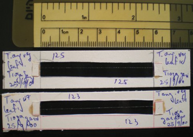
Cardboard frame for measuring stress–strain relations of freshly removed cables with an Instron 5560.
RESULTS
Fibre cables were found in the lacunae of the tall upright leaves of T. angustifolia, T. latifolia, T. × glauca, T. domingensis and T. shuttleworthii. By contrast, fibre cables were absent in the lacunae of the shorter leaves of T. minima and extended for only a few centimetres from the leaf sheath into the leaf blade in T. laxmannii. To characterize the ratio of fibre cable length to the length of the leaf, observations were made in the leaf blade above the attachment of the basal leaf sheath. The length of the leaf (A) from the leaf sheath to the tip of the leaf was measured and the length of the longest fibre cable (B) was determined in a dissected leaf. No leaf contains cables that extend to the tip of the leaf. The ratio (B/A) of the longest fibre cable length to the length of the leaf was recorded from the oldest outer leaf to the youngest inner leaf in vegetative and flowering plants (Tables 1–6). In general, the ratio of the longest fibre cable to leaf blade length increased to a limit in vegetative plants and decreased in flowering plants. The fibre cables (Figs 2 and 3) were similar in all species in which they were present.
Table 1.
Length of leaves and longest cables in Typha angustifolia (Triphammer Road, Ithaca, NY, USA)
| Leaf length (cm) | Longest cable length (cm) | ||
|---|---|---|---|
| Leaf sequence | A | B | B/A |
| Vegetative plant | |||
| 1 | 120·0 | 79·0 | 0·66 |
| 2 | 139·0 | 73·5 | 0·53 |
| 3 | 150·4 | 108·0 | 0·72 |
| 4 | 153·0 | 108·5 | 0·71 |
| 5 | 131·5 | 104·0 | 0·79 |
| Flowering plant | |||
| 1 | 58·0 | 51·0 | 0·88 |
| 2 | 84·5 | 54·0 | 0·64 |
| 3 | 88·0 | 56·5 | 0·64 |
| 4 | 88·0 | 35·0 | 0·40 |
| 5 | 72·5 | 23·0 | 0·32 |
Values in all tables refer to the leaves and cables of one vegetative plant and one flowering plant.
Table 2.
Length of leaves and longest cables in Typha × glauca (Beebe Lake, Cornell University, Ithaca, NY, USA)
| Leaf length (cm) | Longest cable length (cm) | ||
|---|---|---|---|
| Leaf sequence | A | B | B/A |
| Vegetative plant | |||
| 1 | 84·8 | 48·1 | 0·57 |
| 2 | 108·6 | 55·0 | 0·51 |
| 3 | 129·1 | 81·7 | 0·63 |
| 4 | 139·7 | 97·5 | 0·70 |
| 5 | 147·8 | 107·5 | 0·73 |
| 6 | 143·8 | 104·2 | 0·72 |
| 7 | 139·7 | 109·3 | 0·78 |
| 8 | 118·1 | 93·8 | 0·83 |
| 9 | 113·7 | 95·7 | 0·84 |
| Flowering plant | |||
| 1 | 23·4 (tip missing) | - | - |
| 2 | 58·3 | 44·7 | 0·77 |
| 3 | 78·8 | 56·5 | 0·72 |
| 4 | 89·6 | 61·9 | 0·69 |
| 5 | 88·4 | 43·2 | 0·49 |
| 6 | 79·2 | 27·4 | 0·35 |
Table 3.
Length of leaves and longest cables in Typha domingensis (Beer Sheva, Israel)
| Leaf length (cm) | Longest cable length (cm) | ||
|---|---|---|---|
| Leaf sequence | A | B | B/A |
| Vegetative plant | |||
| 1 | 220·4 | 197·9 | 0·90 |
| 2 | 210·4 | 193·0 | 0·92 |
| 3 | 210·5 | 193·7 | 0·92 |
| 4 | 192·9 | 179·2 | 0·93 |
| 5 | 121·0 | 112·5 | 0·93 |
| Flowering plant | |||
| 1 | 174·2 | 144·7 | 0·83 |
| 2 | 180·0 | 144·3 | 0·80 |
| 3 | 177·3 | 151·3 | 0·85 |
| 4 | 166·7 | 141·7 | 0·85 |
| 5 | 159·0 | 133·0 | 0·84 |
| 6 | 137·4 | 108·5 | 0·79 |
| 7 | 111·5 | 84·1 | 0·75 |
| 8 | 77·5 | 53·9 | 0·70 |
Table 4.
Length of leaves and longest cables in Typha latifolia (Kendal, Ithaca, NY, USA)
| Leaf length (cm) | Longest cable length (cm) | ||
|---|---|---|---|
| Leaf sequence | A | B | B/A |
| Vegetative plant | |||
| 1 | 90·6 | 43·2 | 0·48 |
| 2 | 94·9 | 44·7 | 0·47 |
| 3 | 105·0 | 53·7 | 0·51 |
| 4 | 113·3 | 60·1 | 0·53 |
| 5 | 117·8 | 72·7 | 0·62 |
| 6 | 127·4 | 80·0 | 0·63 |
| 7 | 132·8 | 81·27 | 0·61 |
| Flowering plant | |||
| 1 | 72·1 | 17·2 | 0·24 |
| 2 | 75·1 | 28·4 | 0·38 |
| 3 | 74·0 | 31·2 | 0·42 |
| 4 | 75·2 | 24·5 | 0·33 |
| 5 | 70·7 | 25·4 | 0·36 |
| 6 | 65·5 | 15·2 | 0·23 |
| 7 | 60·5 | 3·2 | 0·05 |
| 8 | 50·7 | 0 | 0 |
| 9 | 38·9 | 0 | 0 |
Table 5.
Length of leaves and longest cables in Typha latifolia (Paleontological Research Institute, Ithaca, NY, USA)
| Leaf length (cm) | Longest cable length (cm) | ||
|---|---|---|---|
| Leaf sequence | A | B | B/A |
| Vegetative plant | |||
| 1 | 92·4 | 49·9 | 0·54 |
| 2 | 107·9 | 49·0 | 0·45 |
| 3 | 118·5 | 63·5 | 0·54 |
| 4 | 126·2 | 68·4 | 0·54 |
| 5 | 128·4 | 60·0 | 0·47 |
| 6 | 131·4 | 64·7 | 0·49 |
| 7 | 133·3 | 71·6 | 0·54 |
| 8 | 137·6 | 77·3 | 0·56 |
| 9 | 134·0 | 81·8 | 0·61 |
| Flowering plant | |||
| 1 | 90·9 | 49·3 | 0·54 |
| 2 | 94·7 | 32·0 | 0·34 |
| 3 | 96·2 | 24·7 | 0·26 |
| 4 | 91·0 | 19·6 | 0·22 |
| 5 | 85·9 | 5·0 | 0·06 |
| 6 | 76·6 | 0 | 0 |
| 7 | 64·5 | 0 | 0 |
| 8 | 53·5 | 0 | 0 |
| 9 | 35·0 | 0 | 0 |
Table 6.
Length of leaves and longest cables in Typha latifolia (Whiteknights, University of Reading, UK)
| Leaf length (cm) | Longest cable length (cm) | ||
|---|---|---|---|
| Leaf sequence | A | B | B/A |
| Vegetative plant | |||
| 1 | 69·2 | 26·0 | 0·38 |
| 2 | 78·0 | 31·6 | 0·40 |
| 3 | 91·4 | 47·8 | 0·52 |
| 4 | 104·0 | 45·0 | 0·43 |
| 5 | 119·4 | 58·8 | 0·49 |
| 6 | 133·9 | 65·7 | 0·49 |
| 7 | 145·5 | 67·1 | 0·46 |
| 8 | 161·6 | 78·3 | 0·48 |
| 9 | 175·8 | 91·2 | 0·52 |
| 10 | 192·0 | 104·2 | 0·55 |
| 11 | 190·3 | 95·0 | 0·50 |
| Flowering plant | |||
| 1 | 84·4 | 44·1 | 0·52 |
| 2 | 94·5 | 46·3 | 0·49 |
| 3 | 99·9 | 39·7 | 0·40 |
| 4 | 107·0 | 37·7 | 0·35 |
| 5 | 113·5 | 39·2 | 0·35 |
| 6 | 138·8 | 45·5 | 0·33 |
| 7 | 120·7 | 18·2 | 0·15 |
| 8 | 118·7 | 20·7 | 0·17 |
| 9 | 109·2 | 0 | 0 |
| 10 | 97·8 | 0 | 0 |
| 11 | 83·9 | 0 | 0 |
| 12 | 62·5 | 0 | 0 |
| 13 | 33·9 | 0 | 0 |
Fig. 2.
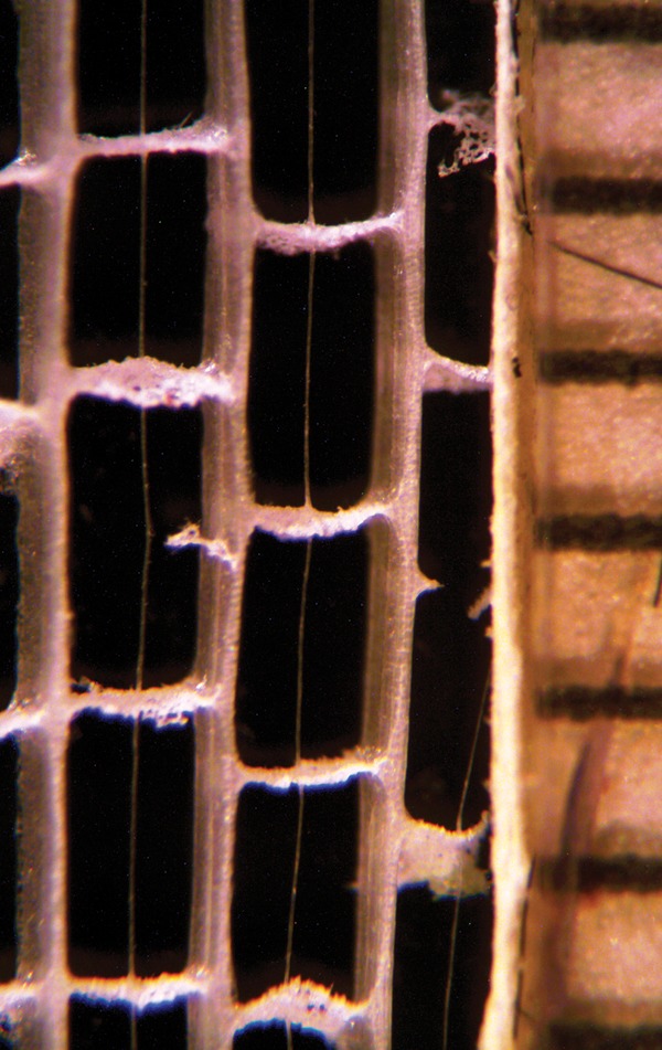
Longitudinal section of the leaf blade of T. × glauca showing fibre cables anchored in diaphragms. The scale on the right is in millimetres.
Fig. 3.
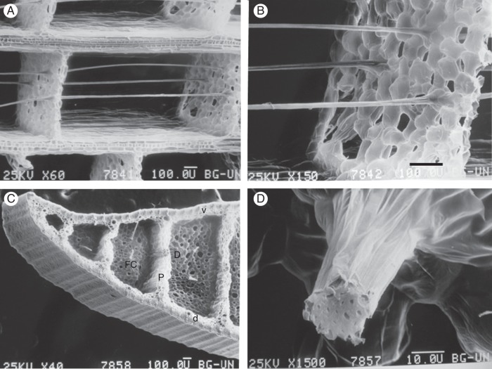
Scanning electron micrographs of the leaf blade of T. domingensis. (A) Longitudinal section showing the fibre cables anchored in diaphragms composed of aerenchyma tissue. (B) Longitudinal section showing the fibre cables anchored in diaphragms composed of aerenchyma tissue. (C) Cross section. The thick ventral (v) and dorsal (d) surfaces of the leaf are separated by thick partitions (P) that run the length of the leaf. Thin diaphragms (D) connected perpendicular to the thick partitions are traversed by very fine fibre cables (FC), which are anchored to them. This construction has often been compared to sandwich-type construction, giving a low-density structure of high stiffness and strength (Rowlatt and Morshead, 1992) that provides the leaf with ‘the greatest strength for the least weight’ (Teale, 1949). (D) Cross section of a cable composed of thick-walled fibre cells with small cell lumens. Scale bar (A–C) = 100 μm; (D) = 10 μm.
Freshly removed fibre cables of T. × glauca were approximately 20–60 μm in diameter (mean ± s.d. 35 ± 5 μm; n = 25). The fibres of the cables that traversed the air lacunae were not lignified (Fig. 4), unlike the vascular bundle fibres and other fibre bundles in the leaf (Fig. 5). The fibre cables were pulled free from the diaphragms of leaves of T. × glauca and placed in maceration solutions in order to separate the cells so that we could determine their lengths (Fig. 6). The fibre cell lengths ranged from about 334 to 1129 μm, with mean ± s.d. 676·5 ± 183·6 μm (n = 69) for fibre cables macerated in Mangin's maceration solution and 663·7 ± 185·8 μm (n = 69) for fibre cables macerated in Jeffrey's maceration solution. Although the sampling technique, which required the presence of both tapered ends of a fibre, was probably biased towards the smaller unbroken fibres, the fibre lengths determined with the two methods were not significantly different (t-test; P = 0·68).
Fig. 4.
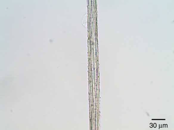
Bright-field micrograph of a fibre cable of T. × glauca treated with phloroglucinol–HCl. The cable fibre did not give the red reaction product typical of lignified cell walls.
Fig. 5.
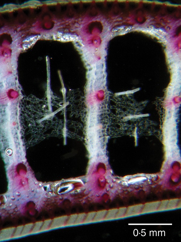
Cross section of a leaf blade of T. × glauca treated with phloroglucinol–HCl. Lignified cell walls that react with phloroglucinol–HCl appear red. The unlignified cell walls of the cable fibres did not react with phloroglucinol–HCl and the fibre cables anchored in aerenchymatous diaphragms appear white.
Fig. 6.
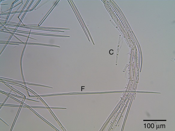
Bright-field micrograph of macerated cells from fibre cables of T. × glauca. The fibre cell (F) with two tapered ends that is bent into an L-shape was ∼881 μm long and 6 μm wide in the middle of the cell. The cover cells (C) of the fibre cable were much shorter (46 μm). Jeffrey's maceration solution dissolved the crystals in the cover cells seen in Fig. 7.
The fibre cables were birefringent and appeared brightly coloured under polarized light with a full-wave plate compensator (Fig. 7). Each cover cell was nearly filled with a plate-like birefringent crystal. The crystals were dissolved in a few minutes by concentrated HCl, indicating that they were not composed of silica (Tomlinson, 1990), like the crystals in the stegmata that are associated with the fibre bundles of palms (Parthasarathy and Klotz, 1976). The crystals in the fibre cables of Typha were probably composed of calcium oxalate, which is also present in druses and raphides in the rest of the leaf.
Fig. 7.
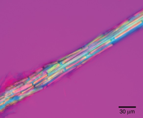
Isolated fibre cable from a leaf of T. × glauca observed with a polarizing light microscope equipped with crossed polars and a full-wave plate compensator. The outer sheath of the cable was composed of cover cells that each contained a birefringent calcium oxalate crystal.
Polarized light microscopy is valuable for determining structural details at the nanometre level that would escape detection in a bright-field microscope (Mohl, 1858a, b; Naegeli and Schwendener, 1892; Ballard, 1917; Wayne 2009a). The orientation of the cellulose microfibrils in the fibre cells of the cables was studied in cables treated with concentrated HCl for 5 min to remove the crystals from the cable cover cells. When the long axis of the fibre cable was oriented parallel to the slow axis of the compensator, the cables appeared blue (Fig. 8A), and when the long axis of the fibre cable was oriented perpendicular to the slow axis of the compensator the cables appeared yellow (Fig. 8B). This indicates that the cellulose microfibrils were predominantly oriented parallel to the long axis of the cable. The cellulose microfibrils in each cable fibre cell were predominantly oriented parallel to the cell's long axis (Fig. 9).
Fig. 8.
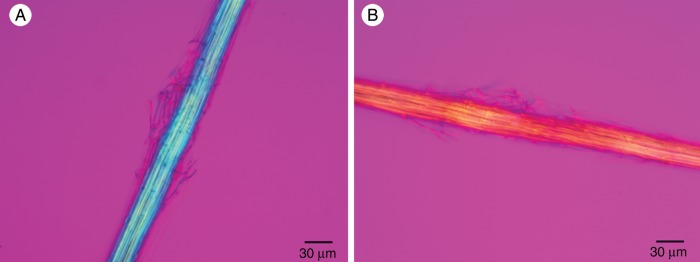
Acid-treated fibre cable of T. × glauca observed with a polarized light microscope equipped with crossed polars and a full-wave plate compensator. (A) The long axis of the fibre cable was oriented parallel to the slow axis of the compensator. The blue additive colour indicates that the cellulose microfibrils were parallel to the long axis of the fibre cable and the slow axis of the full-wave plate. (B) The long axis of the same fibre cable was oriented perpendicular to the slow axis of the compensator. The yellow subtractive colour indicates that the cellulose microfibrils were parallel to the long axis of the fibre cable and perpendicular to the slow axis of the full-wave plate.
Fig. 9.
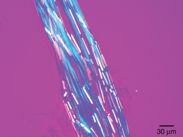
Fibre cable of T. × glauca observed with a polarized light microscope equipped with crossed polars and a full-wave plate compensator. The chemically untreated fibre cable was placed in water and squashed between the cover glass and the slide to push the crystal cells aside and make the fibre cells visible. The long axis of each fibre cell was oriented parallel to the slow axis of the compensator. The fibre cells appear blue because the cellulose microfibrils are parallel to the long axis of each of the individual fibre cells that make up a cable.
A non-uniform arrangement of the chemical bonds of molecules can result in pleochroism, which is the differential absorption or transmission of light depending on the azimuth of polarized light relative to the optical axis. Pleochroism can be used to determine the orientation of anisotropic molecules, such as cellulose, that have been made pleochroic as a result of chemical treatment.
When viewed with linearly polarized light in the absence of an analyser, neither the fibre cables nor the separated fibre cells exhibited pleochroism. However, when iodine (I2KI) was added the walls of the cells of the cable became orange and a small degree of pleochroism was introduced. When the azimuth of polarization was perpendicular to the axis of the cable, the cable transmitted orange light. When the azimuth of polarization was parallel to the axis of the cable, the cable transmitted less orange light and appeared orange, but darker. The pleochroism of the cables was so slight that it was undetectable in single fibre cells (data not shown).
While developing polaroids, Land (1943) found that the pleochroism of cellulose was enhanced by adding zinc chloride to the I2KI. Chloroiodide of zinc is a reagent used as a microchemical test for non-lignified cellulose (Mohl, 1859; Behrens, 1885; McLean and Ivimey Cook, 1941; Brown et al., 1969). This reagent causes non-lignified cellulose to turn indigo-blue. When chloroiodide of zinc was applied to the cables, the cables appeared indigo-blue in a bright-field microscope. When the azimuth of polarization of the incident light was perpendicular to the axis of the cable, the cable transmitted blue light and appeared light indigo-blue (Fig. 10A). When the azimuth of polarization of the incident light was parallel to the axis of the cable, the cable transmitted little light and appeared very dark indigo-blue (Fig. 10B). This pleochroism indicates that the long axis of the cellulose microfibrils was predominantly parallel to the long axis of the cables. Likewise, in squashed cables in which the individual fibre cells could be seen, the cells appeared light indigo-blue when the azimuth of polarization was perpendicular to the long axis of the individual cells and very dark indigo-blue when the azimuth of polarization was parallel to the long axis of the individual fibres (Fig. 11). This orientation of cellulose microfibrils resulted in maximal stiffness (Burgert and Fratzl, 2009).
Fig. 10.
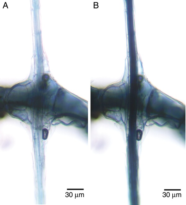
Pleochroism of cellulose observed in a polarizing light microscope without an analyser after treatment with chloroiodide of zinc. (A) A cable anchored in a diaphragm illuminated with linearly polarized light with an azimuth of polarization perpendicular to the long axis of the cable. (B) The same cable illuminated with linearly polarized light parallel to the long axis of the cable.
Fig. 11.
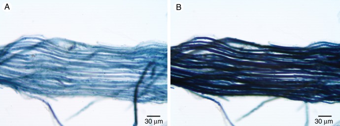
Pleochroism of cellulose observed in a polarizing light microscope without an analyser after treatment with chloroiodide of zinc. (A) A squashed cable showing individual fibres illuminated with linearly polarized light with an azimuth of polarization perpendicular to the long axis of the cable. (B) The same squashed cable illuminated with linearly polarized light parallel to the long axis of the cable.
The maximum tensile strength of freshly removed fibre cables was tested by hanging a weight from a single cable and seeing if the cable remained intact or broke. The greatest weight supported by a cable was recorded and then its diameter was measured (Table 7). The average (± s.d.) maximum tensile strength of a fibre cable was approximately 0·26 ± 0·07 × 109 Pa. Since the fibres make up approximately 72 % of the cross-sectional area of the cable, the maximal tensile strength of the fibre portion of the bundle may be 0·36 × 109 Pa, which is similar to the tensile strength of a cotton fibre (0·25–0·8 × 109 Pa) or of steel (109 Pa; Wayne, 2009b).
Table 7.
Tensile strength of single, not dried, fibre cables of Typha × glauca (Cornell Plantations, Ithaca, NY, USA)
| Cable diameter (μm) | Cross-sectional area of cable (m2) | Attached weight (g) | Pulling force (break load, N) | Maximum tensile strength (MPa) |
|---|---|---|---|---|
| 42·8 | 14·4 × 10−10 | 50 | 0·490 | 340 |
| 54·4 | 23·2 × 10−10 | 50 | 0·490 | 210 |
| 37·2 | 10·9 × 10−10 | 25 | 0·245 | 220 |
| 34·5 | 9·3 × 10−10 | 20 | 0·196 | 200 |
| 34·3 | 9·2 × 10−10 | 30 | 0·294 | 320 |
The mechanical properties of cables of T. latifolia, T. domingensis and T. × glauca were also determined by measuring (on an Instron) load versus extension until the cable broke (Fig. 12A). After the cross-sectional area of the cable had been determined, a derived stress versus strain curve gave tensile strength and stiffness (Young's modulus) values (Fig. 12B; Table 8). The average (± s.d.) maximum tensile strength of the cables stored under room conditions for all the species measured with the Instron was 0·45 ± 0·17 × 109 Pa (n = 20) and that for vegetative T. × glauca was 0·58 ± 0·14 × 109 Pa (n = 6). The difference in maximum tensile strength between determinations made with the hanging weight and the Instron methods may have resulted from a possible reduction in the diameter of the cables from drying under room conditions before they could be analysed with the Instron. The average (± s.d.) Young's modulus of the cables stored under room conditions for all the species measured with the Instron was 22·8 ± 7·4 × 109 Pa (n = 20).
Fig. 12.
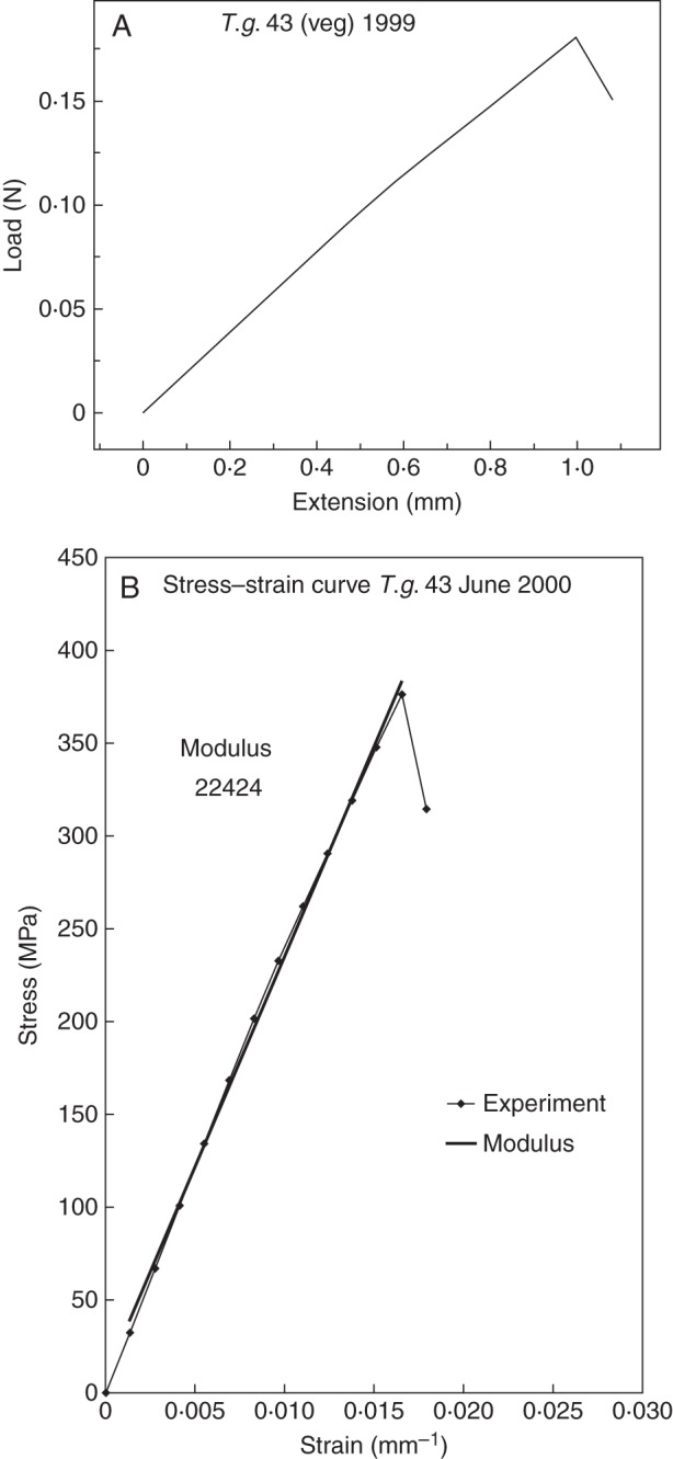
Mechanical properties of fibre cables determined with an Instron. (A) Representative curve of load versus extension for a fibre cable of T. × glauca. (B) Representative curve for stress versus strain for a fibre cable of T. × glauca based on cross-sectional area of the cable.
Table 8.
Microscopic, ultrabalance and Instron-determined parameters for Typha cables
| Sample no. | Diameter (μm) | Weight of 2 cm segment (mg) | Break load (N) | Maximum tensile strength (MPa) | Young's modulus (MPa) |
|---|---|---|---|---|---|
| T. latifolia, flowering | |||||
| 86 | 26·6 | 0·012, 0·011 | 0·116 | 202 | 11 565 |
| 87 | 26·6 | 0·011 | 0·097 | 174 | 7048 |
| 88 | 32·3 | 0·019, 0·018 | 0·198 | 241 | 11 979 |
| 90 | 32·3 | 0·022, 0·026 | 0·260 | 317 | 14 844 |
| 91 | 20·9 | 0·013, 0·014 | 0·150 | 435 | 22 905 |
| T. domingensis, vegetative | |||||
| 118 | 17·1 | 0·005, 0·007 | 0·074 | 322 | 20 147 |
| 119 | 15·2 | 0·007, 0·008 | 0·110 | 607 | 27 553 |
| 120 | 17·1 | 0·008, 0·008 | 0·107 | 466 | 24 197 |
| T. × glauca, vegetative | |||||
| 41 | 24·7 | 0·026, 0·024 | 0·380 | 793 | 35 366 |
| 42 | 22·8 | 0·017, 0·015 | 0·203 | 497 | 20 399 |
| 43 | 24·7 | 0·017, 0·017 | 0·178 | 372 | 22 424 |
| 44 | 24·7 | 0·016, 0·021 | 0·244 | 509 | 22 901 |
| 56 | 24·7 | 0·019, 0·019 | 0·337 | 704 | 33 447 |
| 57 | 19·0 | 0·014, 0·012 | 0·171 | 603 | 32 282 |
| T. × glauca, flowering | |||||
| 4 | 24·7 | 0·022, 0·021 | 0·254 | 530 | 25 283 |
| 21 | 19·0 | 0·011, 0·012 | 0·190 | 670 | 22 314 |
| 22 | 22·8 | 0. 013, 0·016 | 0·164 | 402 | 21 541 |
| 32 | 15·2 | 0·006, 0·007 | 0·087 | 480 | 23 219 |
| 38 | 17·1 | 0·009 | 0·083 | 362 | 25 067 |
| 39 | 17·1 | 0·010, 0·0096 | 0·070 | 305 | 32 064 |
After the 6 cm fibre cable broke in the load versus extension experiment, the diameter of the fibre cable was measured and two 2 cm segments were cut from the broken fibre cable and weighed. For samples 87 and 38, only one weight determination was made.
DISCUSSION
There is currently a resurgence in the use of cattails as sustainable biomaterials for new technologies and traditional handcrafts (Fig. 13; Wiegand and Eames, 1925; Hotchkiss and Dozier, 1949; Teale, 1949; Marsh, 1955; Reed and Marsh, 1955; Armillas, 1971; Morton, 1975; Comstock, 1976; Thieret and Luken, 1996; National Research Council, 2002; Gibson, 2012; Fraunhofer-Gesellschaft, 2013). The utility of Typha leaves is a function of their high structural rigidity and low density. Their high structural rigidity and low density result from their tensegrity structure.
Fig. 13.
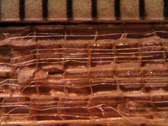
Cables in a fragment of the seat of an old chair made in the Philippines from cattail (T. domingensis?) leaves. The scale is in millimetres.
The dorsal and ventral tissues of the Typha leaf are connected by perpendicular partition (P) struts. These water-filled tissues, which contain lignified fibre bundles and lignified vascular bundles, are strong under compression. The tissues are connected by delicate perpendicular aerenchymatous diaphragms (D) to the very fine fibre cables (FC). The very fine fibre cables that traverse the lacunae are perpendicular to the diaphragms and anchored to them (Fig. 3). The fibre cables, which are stiff and strong under tension, are present in the lower portion of the leaf blade and are absent in the upper part of the leaf blade. Consequently, they contribute to stiffness where the bending moment is greatest. The combination of thick dorsal and ventral leaf surfaces and thick partitions that are strong in compression, connected through the aerenchymatous partitions with the very fine fibre cables that are strong under tension, provide a tensegrity structure that creates multiple load paths (Rowlatt and Morshead, 1992) through which stresses are redistributed so that no particular structure is overstressed to the buckling point (Vincent, 2012). The lightweight tensegrity-structured leaf blade with a large volume of air-filled lacunae allows gas exchange between aerial and submerged parts (Constable et al., 1992; Constable and Longstreth, 1994) and enables the ribbon-like leaves to withstand high winds undamaged (Teale, 1949).
The distal, thinner ribbon-like portion of the long linear leaf blade (which has fewer or no fibre cables) not only bends in the wind, but may also reconfigure (reversible changes in cross-sectional shape), as do the thinner leaf margins of the thicker part of the leaf blade (with fewer fibre cables than the thicker part). Bending and reconfiguration reduce drag force in high wind and prevent damage to the leaf blade (Vogel, 2012).
The absence or minimal presence of fibre cables in smaller-leaved species of Typha and their diminished presence (B/A) or absence in the last-formed and shorter leaf blades of flowering individuals (Tables 1–6) suggest a functional relationship with the support of the leaf blade superstructure.
In flowering and fruiting Typha plants, which have wind-mediated pollen and seed dispersal, the thinner leaf construction of the upper part of the leaf blades, reduced lignified tissue and the absence of fibre cables in the lacunae result in their bending in the wind while the rigid stalk of the inflorescence remains above the wind-bent upper part of the leaf blades. The bending of the distal portion of the leaf blades by wind clears the airways for more effective pollen and seed dispersal. Perhaps the reduction in number and length of cables of leaves in flowering Typha plants is a result of the hormonal changes that occur during floral induction.
What contribution, if any, the crystal-containing cover cells make we do not know, but they are beautiful. We believe, like past observers of Typha leaves, that an understanding of the micro-architecture of these leaves leads to an appreciation of the complex relationship between structure and function.
ACKNOWLEDGEMENTS
A.W. thanks Julian F. V. Vincent and David G. Hepworth for their help and suggestions during his visits to the University of Reading. We thank Frank Telewski of Michigan State University for his review of the manuscript, which pointed out the importance of the fibres in achieving a tensegrity structure.
LITERATURE CITED
- Armillas P. Gardens on swamps. Science. 1971;174:653–661. doi: 10.1126/science.174.4010.653. [DOI] [PubMed] [Google Scholar]
- Ballard CW. Polarized light in vegetable histology. Some investigations of plant histology. Scientific American Supplement. 1917;83:399. [Google Scholar]
- Behrens JW. A guide for the microscopical investigation of vegetable substances. Boston: S. E. Cassino; 1885. [Google Scholar]
- Brown RM, Jr, Franke WW, Kleinig H, Falk H, Sitte P. Cellulosic wall components produced by Golgi apparatus of Pleurochrysis scherffelii. Science. 1969;166:894–896. doi: 10.1126/science.166.3907.894. [DOI] [PubMed] [Google Scholar]
- Burgert I, Fratzl P. Plants control the properties and actuation of their organs through the orientation of cellulose fibrils in their cell walls. Integrative and Comparative Biology. 2009;49:69–79. doi: 10.1093/icb/icp026. [DOI] [PubMed] [Google Scholar]
- Comstock RB. Rush seats for chairs. Cornell Bulletin 683. Ithaca: Cornell Cooperative Extension; 1976. http://dspace.library.cornell.edu/bitstream/1813/3807/2/Rush%20Seats%20for%20Chairs.pdf . Accessed 10 January 2014. [Google Scholar]
- Constable JVH, Longstreth DJ. Aerenchyma carbon dioxide can be assimilated in Typha latifolia L. leaves. Plant Physiology. 1994;106:1065–1072. doi: 10.1104/pp.106.3.1065. [DOI] [PMC free article] [PubMed] [Google Scholar]
- Constable JVH, Grace JB, Longstreth DJ. High carbon dioxide concentrations in aerenchyma of Typha latifolia. American Journal of Botany. 1992;79:415–418. [Google Scholar]
- Fassett NC, Calhoun B. Introgression between Typha latifolia and T. angustifolia. Evolution. 1952;6:367–379. [Google Scholar]
- Fraunhofer-Gesellschaft. Using cattails for insulation. ScienceDaily. 2013. http://www.sciencedaily.com/releases/2013/06/130603091730.htm. and http://www.fraunhofer.de/en/press/research-news/2013/may/using-cattails-for-insulation.html . Accessed 10 January 2014.
- Gibson LJ. Inside plants: an engineer's view of the Arnold Arboretum. Arnoldia. 2012;70:11–19. [Google Scholar]
- Hotchkiss N, Dozier HL. Taxonomy and distribution of N. American cat-tails. American Midland Naturalist. 1949;41:237–254. [Google Scholar]
- Kaul RB. Ontogeny of foliar diaphragms in Typha latifolia. American Journal of Botany. 1974;61:318–323. [Google Scholar]
- Land EH. Light polarizer and process of manufacture. 1943. Patent US2328219 (31 August 1943)
- Marsh LC. The cattail story. Garden Journal. 1955;5(114–115):128–129. [Google Scholar]
- McLean RC, Ivimey Cook WR. Plant science formulae. London: Macmillan; 1941. [Google Scholar]
- McManus HA, Seago JL, Jr, Marsh LC. Epifluorescent and histochemical aspects of shoot anatomy of Typha latifolia L., Typha angustifolia L. and Typha glauca Godr. Annals of Botany. 2002;90:489–493. doi: 10.1093/aob/mcf211. [DOI] [PMC free article] [PubMed] [Google Scholar]
- Meyer FJ. Beiträge zur vergleichenden anatomie der Typhaceen (Gattung Typha) Beiheft zum botanischen Centralblatt. 1933;51:335–376. [Google Scholar]
- Mohl H von. On the investigation of vegetable tissue by the aid of polarized light. Annals and Magazine of Natural History. 1858a;1:198–209. 3rd Series. [Google Scholar]
- Mohl H von. On the investigation of vegetable tissue by the aid of polarized light. Annals and Magazine of Natural History. 1858b;1:263–275. 3rd Series. [Google Scholar]
- Mohl H von. On the supposed existence of cellulose in starch-grains. Annals and Magazine of Natural History. 1859;4:241–254. 3rd Series. [Google Scholar]
- Morton JF. Cattails (Typha spp.)—Weed problem or potential crop? Economic Botany. 1975;29:7–29. [Google Scholar]
- Naegeli C, Schwendener S. The microscope in theory and practice. London: Swan Sonnenschein; 1892. [Google Scholar]
- National Research Council. Making aquatic weeds useful: some perspectives for the developing countries. New York: Books for Business; 2002. [Google Scholar]
- Parthasarathy MV, Klotz LH. Palm ‘wood’. I. Anatomical aspects. Wood Science and Technology. 1976;10:215–229. [Google Scholar]
- Reed E, Marsh LC. The cattail potential. Chemurgic Digest. 1955;14 9,18. [Google Scholar]
- Rowlatt U, Morshead H. Architecture of the leaf of the greater reed mace, Typha latifolia L. Botanical Journal of the Linnean Society. 1992;110:161–170. [Google Scholar]
- Solereder H, Meyer FJ. Systematische Anatomie der Monokotyledonen. Heft I. Pandanales—Helobiae—Triuridales. I. Teil. Typhaceae—Scheuchzeriaceae. Berlin: Gebrüder Borntraeger; 1933. [Google Scholar]
- Teale EW. The strength of the cattail. Natural History. 1949;58:404–407. [Google Scholar]
- Thieret JW, Luken JO. The Typhaceae in the southeastern United States. Harvard Papers in Botany. 1996;8:27–56. [Google Scholar]
- Tomlinson PB. The structural biology of palms. London: Clarendon Press; 1990. [Google Scholar]
- Vincent J. Structural Biomaterials. 3rd edn. Princeton: Princeton University Press; 2012. [Google Scholar]
- Vogel S. The life of a leaf. Chicago: University of Chicago Press; 2012. [Google Scholar]
- Wayne R. Light and video microscopy. Amsterdam: Elsevier/Academic Press; 2009a. [Google Scholar]
- Wayne R. Plant cell biology: from astronomy to zoology. Amsterdam: Elsevier/Academic Press; 2009b. [Google Scholar]
- Wiegand KM, Eames AJ. The flora of the Cauga Lake basin, New York. Vascular Plants. Memoir 92 of the Cornell University Agricultural Experiment Station. Ithaca: Cornell University Press; 1925. [Google Scholar]


