Abstract
Background
Peg transfer is one of five tasks in the Fundamentals of Laparoscopic Surgery (FLS), program. We report the development and validation of a Virtual Basic Laparoscopic Skill Trainer-Peg Transfer (VBLaST-PT©) simulator for automatic real-time scoring and objective quantification of performance.
Methods
We have introduced new techniques in order to allow bi-manual manipulation of pegs and automatic scoring/evaluation while maintaining high quality of simulation. We performed a preliminary face and construct validation study with 22 subjects divided into two groups: experts (PGY 4–5, fellow and practicing surgeons) and novice (PGY 1–3).
Results
Face validation shows high scores for all the aspects of the simulation. A two-tailed Mann-Whitney U-test scores showed significant difference between the two groups on completion time (p=0.003), FLS score (p=0.002) and the VBLaST-PT© score (p=0.006).
Conclusions
VBLaST-PT© is a high quality virtual simulator that showed both face and construct validity.
Keywords: Physics-based simulation, minimally invasive surgery, Haptics, virtual reality, surgical simulation, face validation, construct validation
Introduction
With its many advantages of faster recovery, minimal blood loss and lower cost of treatment, minimally invasive surgery (MIS) is becoming widely accepted as the preferred means of performing many types of surgeries [1]. However, MIS is more demanding in terms of surgical skill level due to difficult hand-eye coordination, two-dimensional field of view and lack of perceivable haptic feedback. Hence, besides attaining procedural knowledge, the surgeons should go through a well defined curriculum in order to train in basic skills and specific baseline sub-procedures.
In view of this, the Fundamentals of Laparoscopic Surgery (FLS) was introduced to systematize the evaluation of both cognitive and psychomotor skills required to perform MIS [2]. The psychomotor component of the FLS is a trainer tool box that allows testing of five pre-defined tasks: peg transfer, pattern cutting, ligation loop and suturing with intracorporeal as well as extracorporeal knot tying. These tasks were designed to train surgical residents in acquiring skills to perform surgical tasks such as picking, transferring between dominant and non-dominant hands, knot tying, precision cutting and ligating slender structures. Task-specific metrics have been developed by the FLS committee to evaluate performance of each of these tasks. Certified FLS scorers are currently used for subjective evaluation. The scores are based on competition time, precision and task specific errors.
In the current FLS system, the overall process of performing the tasks to obtaining the scores entails a considerable amount of labor, time and cost. Test takers must perform the tasks at the regional test centers or at the annual SAGES or ACS meeting to be evaluated by certified proctors. In addition, the FLS is an evaluation system with no provision for proper feedback in the absence of highly qualified proctors during the training phase. There is, therefore, significant interest in automating the testing and scoring process. Accomplishing this with the FLS box using computer vision and sensor technology, along the lines presented in [3] and [4] may be challenging without a significant increase in simulator cost. This has motivated us to pursue a virtual reality (VR) based FLS training simulator that can automate the scoring and evaluation process using objective metrics. Additionally, VR based simulators can be easily tuned to provide haptic/visual guidance for learning and provide objective metrics of performance which are otherwise not possible through a physical training box. The Virtual Basic Laparoscopic Skill Trainer (VBLaST©) is being developed as a virtual reality simulator to perform the FLS tasks, which is capable of automatic scoring based on the FLS system ([5], [6]).
With the advent of faster computing resources, interest has grown towards computer-based VR training systems. Over the years many VR based simulators have been developed for skill training, imparting anatomical/procedural knowledge and patient rehabilitation. Many software platforms have also been introduced for VR based surgery simulation ([7][8][9][10]). These platforms feature a highly structured code that has all the basic components to aid faster development of surgery simulation. We refer to ([11],[12]) for comprehensive survey on existing simulators and their functional capabilities. VR based simulators were proven to improve operating room performance there by reducing the errors during surgery ([13],[14]). Some simulators are aimed at training in specific procedures (procedural simulators) ([15],[16],[17]), while others aim at specific tasks like needle insertion and steering[18] and bone drilling[19] among others (part-task simulators). Such simulators have many advantages. They reduce the long-term training costs, allow objective assessment of skill deficiencies using new metrics, lend portability and provide immediate performance feedback. However, to prove these simulators are effective, they have to show face, construct and predictive validity. Numerous such validation studies performed in the past have proven the validity and advantages of these virtual trainers ([20],[21],[6],[22]).
In this paper we discuss the development and validation of the VBLaST© peg transfer (VBLaST-PT©) simulator for performing the peg transfer task based on the FLS protocol. There have however been virtual versions of the FLS tasks developed before. LAP Mentor™ (Simbionix USA, Cleveland, Ohio) [23] is a library of modules designed for training in basic laparoscopic skills as well as complete procedures such as ventral hernia, gastric bypass, sigmoidectomy etc. The simulator consists of custom hardware interface with haptic feedback. The Basic Laparoscopic Skills Acquisition module in LAP Mentor™ is designed for training in basic laparoscopic skills such as camera manipulation, hand-eye coordination, clipping, grasping, cutting and electrocautery [24]. The Peg Transfer, Pattern Cutting and Ligating Loop are the three tasks that are part of the Laparoscopic Essential Tasks sub module. Preliminary validations of the three tasks have been performed [25]. The results showed a moderate concurrent validity for the three tasks with significant differences in completion time between the FLS and the Lap Mentor™. To best of our knowledge, the three tasks do not use the same scoring metrics that is used in the FLS.
Lap-X [26] is another simulator that offers FLS tasks like peg transfer, pattern cutting and suturing. Lap-X design is centered on portability and hence features a light user interface that does not support haptic feedback which is an essential component of peg transfer task. To our knowledge Lap-X has not been clinically validated. The LapVR (Immersion Medical, Gaithersburg, MD) provides a similar task to peg transfer ([27][28]). The simulation involves placing capsule shaped objects in the holes. This task differs significantly to the FLS peg transfer. LapSim [29] is another training system that features training for basic laparoscopic skills to specific advanced procedures like appendectomy and hysterectomy. Lapsim’s task training module features tasks that are similar to that in FLS. However the task resembling peg transfer deviates significantly from the FLS peg transfer. Almost all of the above mentioned simulators have their own user interfaces capable of 3-dof force feedback. Since the interfaces are designed to be used for all the modules of the training system their configuration deviates from that specified by FLS and also come at a high price.
Previously developed simulators have not provided fully functional tasks close to the actual FLS and lack high fidelity multimodal feedback with automated scoring system of the FLS. In this paper we discuss the development of VBLaST-PT© which tries to provide simulation experience closer to the real FLS. This is achieved by (a) a high quality simulation with multimodal real-time feedback (b) working with SAGES to incorporate the scoring mechanism used in the FLS (c) validating the simulator by performing face, construct and concurrent validation studies. This paper addresses points (a), (b) and part of (c). We have developed a custom hardware enabling multimodal interactions with the simulation. This interface enables 5-dof tool motion (x, y, z translation, rotation about the roll axis and open/close of jaws), provides 3 degree of freedom (dof) force feedback and enables easy tool exchange and workspace adjustments. We have developed a computationally efficient and realistic method to simulate picking and interaction thereafter of the peg with single and both the tools. This method provides reliable visual and haptic feedback for the user without sacrificing the frame rate of the simulation. The simulation also automatically detects and analyzes all stages of the peg transfer task like picking, transferring and any dropping of the pegs in and out of the board. This data can be used for further offline analysis.
The remainder of the paper is organized as follows: The section to follow presents the various simulation methods employed as well as the hardware interface for VBLaST-PT©, followed by results section discussing the results from face and construct validation. The final section discusses the conclusion and future work.
Materials and Methods
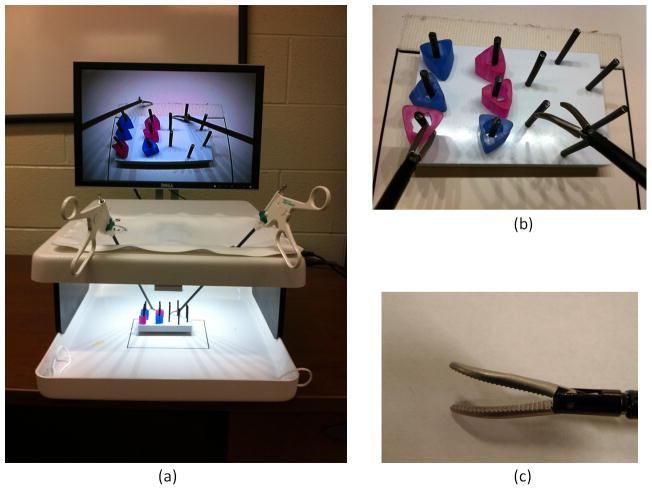
The FLS protocol for the peg transfer task involves transferring six pegs from six posts on one side to the other and vice versa using actual laparoscopic grasping tools shown in Figure 1. This task is designed to test various skills including hand-eye coordination, bimanual dexterity, speed and precision. These skills are essential to any minimally invasive surgical procedure, e.g., the skills acquired from the peg transfer task directly translate into better bimanual handling of needle and other small objects during surgery. A proprietary scoring system is employed that uses metrics such as time and errors [30].
Figure 1.
(a) FLS work station showing FLS trainer box with peg transfer setup (b) peg transfer involves transfering the pegs from peg posts on the left to those on right and vice-versa (b) Maryland graspers with curved jaws are used for peg trasnfer.
The VBLaST-PT© consist of a hardware interface and a software platform. We have worked with SAGES to develop a scoring system based on the FLS. Figure 2 shows the overview of the overall simulation framework which consists of four main components: (a) simulator module (b) hardware interface module (c) data recording module and (d) display module. The haptic devices and tool handle values are continuously read in two separate program threads. The physics-based simulation is run in a separate thread. All collisions are resolved and force values are computed in this thread. We use Open Dynamics Engine (ODE) for physics-based simulation [31]. All the collision structures are initialized at the start of the simulation while the constraints from the grasping mechanisms are provided during the simulation.
Figure 2.
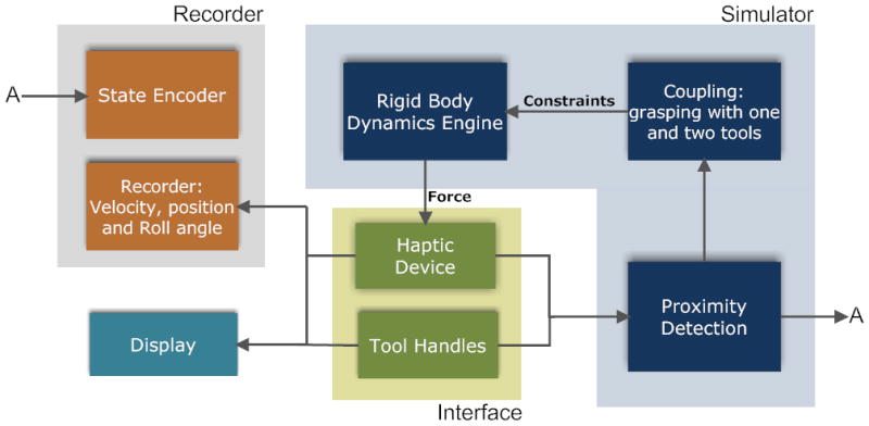
Overall schematic of the VBLaST-PT© simulation software
The recording module collects the data from the existing states and writes onto an external file. A buffer of fixed size is used for data recording. The data is written onto the file only when the buffer is full. This allows for better performance as read/write operations onto an external file is expensive. The essential components in the overall schematic in Figure 2 are explained in the subsections below.
Hardware Interface
We have developed a specialized interface (see Figure 3) for the VBLaST© that can be used for all five tasks by just interchanging the instrumented tools connected to the interface. The basic structure of the interface is built using aluminum frames that allow height adjustments as well as adjustments to the horizontal positioning of the haptic devices and trocars. Two Phantom® Omni™ haptic interface devices from Sensable® Inc are used with the end effectors modified to connect to the surgical tools that are placed through the trocar assembly. These haptic devices are capable of providing force feedback in x, y and z directions. Trocars are fit into a 2-axis gimbal mechanism shown in Figure 3(a). This gimbal arrangement allows for rotation in the left-right and forward-backward directions. The rotation and translation of the tool about its own axis is, of course, allowed.
Figure 3.
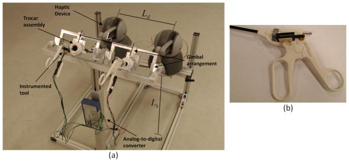
(a) Tool interface assembly (b) Close-up of the tool handle with potentiometer
A BEI Duncan 0.5 inch linear potentiometer (BEI Duncan Electronics Inc.) is connected to each tool (Figure 3 (b)) using a simple attachment that converts the angular motion of the tool handles to the linear motion of the potentiometer. This linear motion, interpreted as an analog voltage signal, is digitized and fed to the simulation software using ADU100 analog-to-digital converter form Ontrak® control systems. We take advantage of the tool-haptic device attachment to directly read the tool rotation about its own axis from roll angles of the haptic device.
We also analyzed the workspace of the interface in order to place the haptic devices without fouling with each other [32]. Table 1 shows the ranges and final values of various adjustable lengths for the interface marked in Figure 3. The values of various distances are set such that all the movements within the workspace are possible while ensuring that the Phantom® ends do not interfere physically with one another.
Table 1.
Range and final values for various adjustable distances in the interface
| Distance Parameter | Range(mm) | Set Value (mm) |
|---|---|---|
| Distance between haptic devices (Ld) | 70–480 | 380 |
| Trocar placement distance (Lt) | 80–360 | 280 |
| Trocar assembly height (Lh) | 400–750 | 635 |
To ensure that the workspace in the VBLaST-PT© coincides with the workspace in the FLS toolbox, all major physical and model dimensions in the virtual simulator must be scaled by the ratio of the distance between the trocars in the two systems (Figure 3(a)). In addition, the camera angles in the two systems must also be identical.
Computational Modeling
Several innovations in computational modeling that have enabled VBLaST-PT© are discussed below. The slight flexibility of the pegs in the FLS box is not relevant to the task of picking and transferring them. We have therefore modeled the pegs as rigid bodies in VBLaST-PT©, which significantly improves computational efficiency. The pegs interact with the rigid peg board (Figure 1) that has twelve posts arranged differently, six on each side. During the simulation, the two tool graspers are used to manipulate the position and orientations of the pegs. The pegs can be picked up and transferred from one tool to the other. All the interactions are modeled as rigid-rigid interactions with force feedback. The technique of modeling interactions between the tools and the peg-board and pegs with the exception of picking, is presented in section 2.2.1.
Unlike most rigid body simulations, the tools are controlled in real-time by the user. Therefore, additional care must be taken when a user picks a peg with one or both tools or constrains the peg against the peg board. Virtual coupling schemes used for picking using one and two tools simultaneously, picking and release conditions are presented in the three subsections to follow.
Tool interactions
The interaction between a haptic interaction point (HIP) and a polyhedral scene is enabled by the ‘god object’ algorithm [33]. A simple spring and damper is applied between the HIP and the god object (virtual) to create an accurate visual rendering as well as appropriate haptic perception of pushing against a hard object. In [34] and [35], the authors extend the god object method to enable torques during the interaction. In our simulation the tools and pegs are, however, extended objects and no torque interactions are modeled.
The curved rigid jaws of the Maryland graspers (Figure 3(c)) are modeled using a simple link assembly as shown in Figure 4. The linkage assembly consists of two cylindrical objects that are fixed with respect to each other in orientation and position which are in turn linked to a spherical pivot. The angles and sizes are proportioned to approximate the shape and size of the curved jaws. The relative position and orientation of the whole assemblage is fixed except when the jaws are opened or closed by the user. If the jaw is opened or closed, the relative angles of the cylinder assemblages is changed with respect to the sphere in opposite directions. The whole jaw assemblage is also assigned a mass and is treated as a rigid assemblage by the rigid body dynamics engine. The orientation of the whole assemblage is controlled by the orientation of the haptic device. In order to constrain the position, it is connected to the HIP of the haptic device using a spring and damper (Figure 4). During interactions, the user feels a force that is proportional to the spring force. The god object for the display follows the linkage both in position and orientation.
Figure 4.
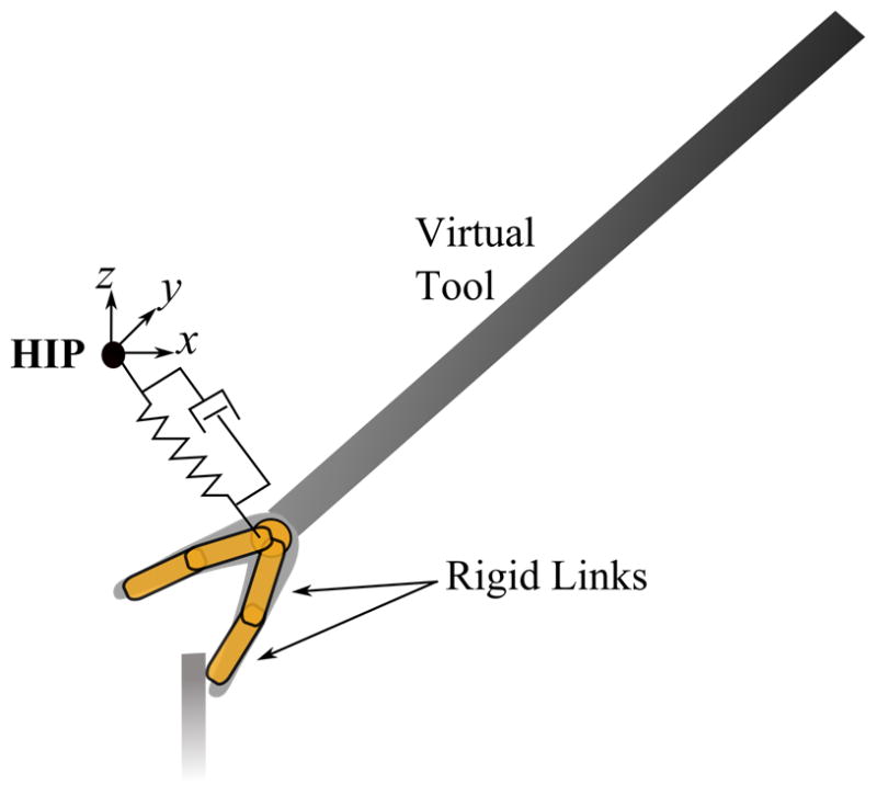
Modeling of the tool for interaction using virtual spring and damper. The distances shown here are exaggerated for illustration purposes.
The collision structures for the peg posts are modeled as cylindrical objects fixed both in position and orientation. The peg board is modeled as a planar surface. Hence, a user may interact with the peg board and pegs without penetration while creating the proper visual and haptic perception.
Grasping using a single tool
Picking pegs using graspers requires modification to the algorithm presented above. When picked, the peg is held static with respect to the tool. We simulate the picking process by supplying appropriate constraints to the peg. Table 2 explains various variables used in this section.
Table 2.
Explanation of variables
|
|
Orientations of tool (t) and peg (p) at the time of picking with respect to the global coordinates. | |
| Rt, Rp | Orientation of tool (t) and peg (p) at any given time with respect to the global coordinates. | |
| HIP′ | Position of the haptic device at the time of picking with respect to the global coordinates. | |
| HIP | Position of the haptic device at any given time with respect to the global coordinates. | |
|
|
Relative position of the peg with respect to the tool calculated in the local coordinates of the device at the time of picking. | |
|
|
Relative position of the spherical pivot with respect to the local coordinate system of the peg at the time of picking | |
|
|
Absolute position of the peg at the time of picking. | |
|
|
Absolute position of the spherical pivot at the time of picking. | |
|
|
Absolute position of the peg’s target. | |
|
|
Absolute position of the virtual tool after picking. | |
| pp | Position of the peg at any given time after picking. |
When the tool jaws are positioned and the picking condition is satisfied, the peg’s relative position is calculated in the local coordinates of the device as
This is used to calculate the target position (see Figure 5) of the peg during the subsequent simulation steps. The relative position of the spherical pivot is then calculated with respect to the peg’s local coordinate system as
Figure 5.
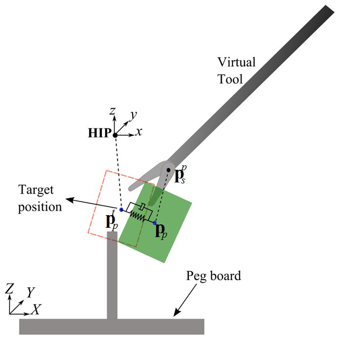
Cartoon illustrating the coupling mechanism when picked by one tool
After picking, the rigid peg is constrained to rotate with the haptic device. The position of the peg is controlled by a spring and damper shown in Figure 5. The peg is constrained by the spring and damper to the target position calculated from as
The force rendered to the user is proportional to . The display of the tool shaft and the jaws are now shifted to position . The tool follows the haptic device orientation as the peg. This maintains the relative position and orientation of the peg with respect to the tool. One can also interact with the pegboard and peg posts with correct visual and haptic feedback.
When the peg is released, the spring and damper are removed and the virtual tool is again displayed at the spherical pivot. The jaw assembly always follows the haptic point closely, and this allows smooth transition. The jump in force is also imperceptible since
Hence,
Two-way coupling for grasping with two tools
As the peg is transferred from one tool to another, the user momentarily grasps the peg with both the tools. One has to simulate this state in order to provide the right cue before releasing the peg from one tool to the other. We have extended the virtual coupling method described above in order to simulate this condition.
When the peg is grasped by the second tool, a coupling mechanism similar to the one discussed in the previous section, is used. However, this leads to constraining the peg using two sets of springs and dampers (see Figure 6). As before, the force rendered on each tool is proportional to the difference in target point for the peg and the current peg position. The virtual display of tools is positioned at and for the left and right tools, respectively, where are the relative positions calculated in the reference coordinates of the respective devices. Since the peg position is controlled by both the graspers, there is an indirect reaction force generated on both the tools when one of them is moved. This replicates the real scenario of grasping with both tools. The peg reaches the equilibrium point (Figure 6) quickly, within a few time steps, resulting in generation of equal and opposite forces one each device.
Figure 6.
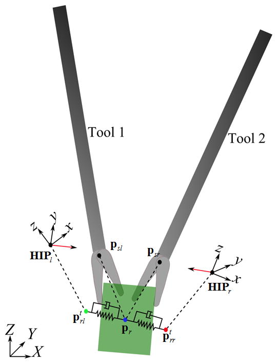
Cartoon illustrating the mechanism used when the peg is picked by both the graspers
The procedure described above creates a mechanism whereby a tool, when moved, transmits the force to the other tool automatically. This allows physically realistic grasping of the peg with both the tools simultaneously.
Picking and release conditions
Conditions must be set to decide when a peg has been picked or released. A peg is detected as picked if all of the following conditions are met: (a) the angle between jaws is below a threshold θpick; (b) the jaws are closing, i.e., θt+Δt < θt where θt, θt+Δt are the jaw angles at times t and t+Δt, respectively; and (c) either, but not both, the contact points between the jaws and the bounding box of the hole are inside the bounding box (Figure 7). We keep track of the nearest peg to each post at all times during the simulation. The bounding box test is performed with the nearest peg. These conditions ensure that the peg is not picked at orientations and positions that are physically improbable. The peg is released if (a) the jaw is opening that is θt+Δt > θt and (b) the angle between jaws exceeds a certain threshold θrelease.
Figure 7.
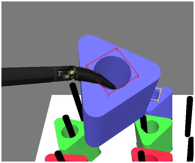
Bounding box of the cylindrical hole for the peg used for detecting picking and release
Automatic data recording and evaluation
A major advantage of virtual reality based simulators is the ability to automate evaluation and record multidimensional performance measures. Such metrics may be used to conduct in-depth analysis of the level of proficiency of the user. Previous studies have shown substantial promise in detecting key aspects of the differences between novice and experts [36] which is otherwise not possible.
In our peg transfer simulator, we record the following metrics at a frequency of 30Hz
states of all the six pegs (if changed)
Position of the tool pivot
velocity of the tool pivot
roll angle of the tools
time stamp for state change of each peg
Overall time to complete the task
To prevent slowdown of the simulation, we use a buffer of fixed size for recording purposes. Since writing to an external file is an expensive operation, it is done intermittently only when the buffer is full.
Based upon FLS, performance scores are computed using task time as well as the number of pegs dropped out of the board. In the case of FLS evaluation, the evaluator observes the task being performed and records the time and number of dropped pegs manually. However within VBLaST-PT©, one has to device a mechanism to detect a peg being dropped inside and outside of the board. To facilitate this, we have designed an encoder that outputs a series of numbers that corresponds to the ‘states’ of each of the pegs during the simulation. Ten such ‘states’ are possible (Table 3) numbered 0 to 9. Each peg is in one of these states during the simulation at all times.
Table 3.
Peg states and their corresponding integer codes
| 0 | Peg is on peg to the right |
| 1 | Peg is on peg to the left |
| 2 | Peg on ground and not on any peg |
| 3 | Peg has been picked by the right tool |
| 4 | Peg has been picked by the left tool |
| 5 | Peg has been transferred from right to left tool |
| 6 | Peg has been transferred from left to right tool |
| 7 | Peg has been dropped by the right tool |
| 8 | Peg has been dropped by the left tool |
| 9 | Peg is outside of the board |
Each simulation generates a string of peg states which are then decoded by a Matlab® (Mathworks Inc.) script. Figure 8 shows some examples. If the code 2 appears in the sequence between 4 and 3 then the peg is dropped during the transfer. A perfect transfer from left to right and reverse is characterized by a sequence shown in Figure 8. We further record the time instance at which these events occur. Velocity and position data are recorded at a preset frequency for both tools. All the combinations are automatically analyzed in the post processing stage in order to detect the number of times each peg is dropped on the board and the number of pegs dropped outside the board that were not retrieved. These measures along with the time taken to perform the task are used in deciding the final score.
Figure 8.
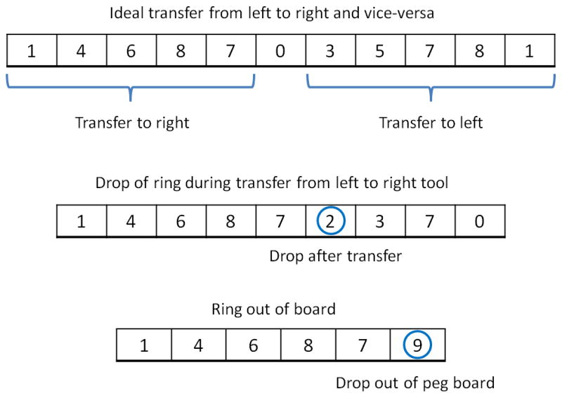
Some interpretations of the number sequences denoting peg states automatically generated during simulation
Since peg transfer is a modular task, it is appropriate to derive time metrics for each of these tasks. Our program detects the individual peg transfer times along with peg drops. The program automatically generates a Matlab® script that produces this statistic for all the pegs as shown in Figure 9. All blue histograms represent transfer from left to right while green histograms represent transfers from right to left. If a peg is dropped or pushed outside the board, the histogram is colored purple. Since the peg cannot be retrieved if the peg is dropped outside, the time is set to −1. This information can be used to detect if there is a difference in skill level while transferring from left to right versus from right to left.
Figure 9.
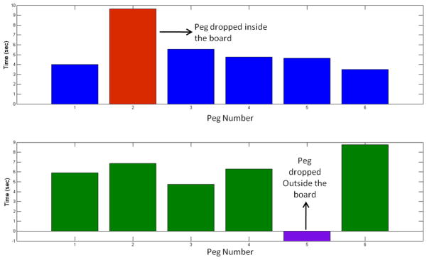
Automatic detection of transfer times for each peg separately from left to right and vice-versa. The peg that is dropped both on and off the board is also detected as shown in red and violet, respectively.
Further, the velocity and position data recorded can be used to derive the spatial signatures for each subject for both hands. One can visualize how a subject utilizes the workspace, i.e., how a subject is ergonomically efficient in completing a task by computing objective metrics such as length of trajectory (LOT) and economy of motion. Previous studies showed that such signatures are useful in differentiating novice from experts [36].
Face and Construct validation
The VBLaST-PT© simulator was displayed for three days at the Learning Center of the 2012 Society of American Gastrointestinal and Endoscopic Surgeons (SAGES) annual meeting held in San Diego, CA. A preliminary face and construct validation study was conducted based on a protocol approved by the Institutional Review Board (IRB) at Rensselaer Polytechnic Institute. Subjects were voluntarily recruited and asked to perform the peg transfer task on both the VBLaST-PT© simulator and the FLS tool box. The order in which the simulators were presented to each subject was randomized. Subjects were given up to two practice trials to get familiar with the procedure and the system. After the completion of the tasks the subjects were asked to answer a feedback questionnaire, consisting of nine questions (Table 4) comparing various aspects of the two simulators. The questions were posed relating to visual appearance, haptic feedback, 3D perception, tool movement and overall quality and reliability of the simulation as a training and assessment tool. The subject performance scores based on the proprietary formula on both the FLS (manually) and the VBLaST-PT© (automatically) were computed.
Table 4.
Feedback questionnaire
| Question No. | |
|---|---|
| 1 | Please rate the degree of realism of the target objects (how realistic they look) in the VBLaST task environment, compared to the corresponding task environment in FLS |
| 2 | Please rate the degree of realism of instrument handling (how realistic it feels) in the VBLaST, compared to that in the FLS |
| 3 | Please rate the degree of overall realism of the VBLaST simulation (how it looks and feels), compared to the corresponding FLS task. |
| 4 | Please rate the quality of the force feedback (sensation of feeling the tools on the target and in the task space) in the VBLaST compared to the FLS. |
| 5 | Please rate the degree of usefulness of the force feedback (sensation of feeling the tools on the target and in the task space) in the VBLaST in helping your performance. |
| 6 | Please rate the usefulness of VBLaST simulation in learning hand-eye coordination skills, compared to the FLS. |
| 7 | Please rate the usefulness of VBLaST simulation in learning ambidexterity skills, compared to the FLS. |
| 8 | Please rate the degree of overall usefulness of the VBLaST in learning the fundamental laparoscopic technical skills compared to the FLS. |
| 9 | Please rate your assessment of how trustworthy the VBLaST is to quantify accurate measures of performance. |
The study involved 22 subjects in total with all of them having a medical background. The subject pool consisted of surgeons, PGY 1–5 and research fellows from wide age groups (25–60 years). The subjects were divided into two groups of experts (PGY 4–5, fellow and practicing surgeons) and novice (PGY 1–3). In total the study comprised of 11 experts and 11 novices. IBM SPSS 18.0 was used for statistical analysis. Descriptive statistics for both the combined and the individual scores for experts and novice groups were computed. A two-tailed Mann-Whitney U-test was used to test the significance in the responses on the questionnaire and the performance scores between the two groups.
Results
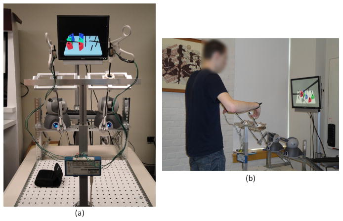
The VBLaST-PT© simulator runs on a desktop computer equipped with a 2.66GHz Core2 Quad CPU supported by 2.75GB physical RAM and two NVIDIA GeForce 8800 GTX graphics cards. Figure 10 shows the simulator setup during operation while Figure 11 shows the screen shots of the VBLaST-PT© at various stages during the peg transfer task.
Figure 10.
(a) VBLaST-PT© simulator setup (b) subject performing on the VBLaST-PT© module
Figure 11.
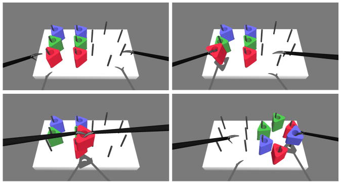
Snapshots of the simulation during various stages of the peg transfer task.
In order to test the quality of simulation under varying computational load that might occur while performing the task, we increased the number of rigid bodies in the scene. Figure 12 shows the average computation times with the increase in number of movable rigid bodies. We estimate the times by increasing the number of movable rigid bodies that is the pegs in the scene that can collide with the board, graspers and with each other. The computational load observed is less than 1 millisecond until nearly 1300 triangles (13 objects). In the peg transfer simulation, the number of triangles of the freely movable rigid bodies is 612.
Figure 12.
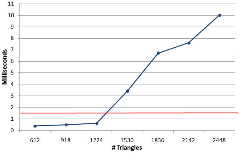
Computation time with the increase of number of movable rigid rings in the scene.
The results of our face validation study are shown in Table 5. The table shows the mean and standard deviation of the scores obtained from the feedback study for each of the nine questions. The Mann-Whitney U-test, comparing the difference of opinion between expert and novice groups did not show any significance for all the questions (i.e., both expert and novice showed general agreement). The least mean score received for any question was 3.59 for the quality of instrument handling. The highest mean was 4.41 for the usefulness of force feedback for task completion. The maximum standard deviation is 1.02 which is reported for the Overall usefulness of VBLaST-PT© in training for FLS skill set. The maximum score received for all the questions is 5.
Table 5.
Descriptive statistics obtained from the feedback study
| Questionnaire | Total | Expert | Novice | Mann-Whitney U-test P-value | |||
|---|---|---|---|---|---|---|---|
|
| |||||||
| Mean | SD | Mean | SD | Mean | SD | ||
| 1. Realism in
rendering
|
4.04 | 0.72 | 4.18 | 0.75 | 3.91 | 0.70 | 0.372 |
| 2. Realism in
tool handling
|
3.59 | 0.67 | 3.45 | 0.69 | 3.73 | 0.65 | 0.440 |
| 3. Overall realism
compared to FLS
|
3.77 | 0.75 | 3.73 | 0.65 | 3.82 | 0.87 | 0.823 |
| 4. Quality of force
feedback
|
4.04 | 0.90 | 3.82 | 0.87 | 4.27 | 0.90 | 0.308 |
| 5. Usefulness of force
feedback In task completion
|
4.41 | 0.73 | 4.45 | 0.52 | 4.36 | 0.92 | 0.800 |
| 6. Usefulness:
Hand-eye co-ordination
|
4.14 | 0.71 | 4.0 | 0.77 | 4.27 | 0.65 | 0.775 |
| 7. Usefulness:
Ambidexterity
skills
|
4.14 | 0.89 | 4.09 | 0.83 | 4.18 | 0.98 | 0.917 |
| 8. Overall usefulness
of VBLaST in training for FLS skill set
|
3.91 | 1.02 | 3.73 | 0.79 | 4.09 | 1.22 | 0.415 |
| 9. Trustworthiness of VBLaST | 3.82 | 0.66 | 3.82 | 0.60 | 3.82 | 0.75 | 0.863 |
Figure 13 shows the box plot comparing the scores of novice and experts on both the FLS and the simulator. This is in fact tested to be statistically significant with p=0.002 for the FLS and p = 0.006 for the VBLaST-PT© We also tested to see if the competition time on VBLaST-PT© alone would be able to differentiate between the groups. The expert group recorded lower time compared to novice group which is shown in Figure 14(b) as a box plot. We also performed a similar analysis on the FLS completion time (Figure 14(a)). Overall the completion time on FLS was lower than the VBLaST-PT©. Both the completion times showed a significant difference between the two groups (p=0.003).
Figure 13.
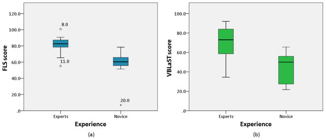
Box plot comparing the total scores for experts and novice groups. Subjects 8, 11 and 20 are shown to be outliers.
Figure 14.
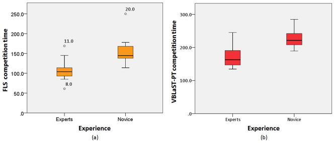
Box plot comparing the completion time for experts and novice groups.
Discussion
Virtual reality based trainers are becoming more common with realistic graphics and other modalities of feedback with the ultimate aim of making the medical training effective and cheaper in a long run [8]. The main challenges involved in developing these simulators are maintaining high visual/haptic fidelity and automatic scoring/evaluation. In this paper, we presented the development of a virtual peg transfer simulator - the VBLaST-PT©. This simulator is capable of high fidelity force feedback along with fully automated scoring and evaluation based on the FLS metrics.
The software architecture is shown in Figure 2 is composed of four modules (a) simulator module (b) hardware interface module (c) data recording module and (d) display module. The simulation module updates the rigid body dynamics of the scene respecting the constraints both from the collisions and that additionally provided due to multi-tool virtual coupling mechanisms discussed above. This module constitutes the main computational load of the simulator. The hardware module receives the analog signals and converts them into the digital signals and feeds to the simulator. In our simulator the hardware module continually reads the tool positions and orientations as well as the opening and closing of the jaws. The recording module runs in a separate thread and records all the required data mentioned previously. The display module utilizes OpenGL APIs for rendering the scene.
Experiments performed to test the frame rate of simulation when more objects are processed in the scene shows that even with varying load of the computation the simulator will be able to maintain the haptic rates (~ 1000). The increase in computational load is attributed to the dynamics engine and the collision detection algorithm. Since in the peg transfer simulation, the number of triangles of the freely movable rigid bodies is relatively low at 612, higher frame rates at all times during the simulation can be assured.
The face validation results show high favorable ratings for all aspects of the simulation. The Mann-Whitney U-test suggests that there was no difference of opinion between the two groups on all the questions. There is also a tight agreement amongst the subjects which is evident from the low standard deviation. The subjects were also asked to provide additional comments on the simulation experience. Some subjects felt that it was slightly more difficult to maneuver the tools in the VBLaST-PT© compared to FLS. This is attributed to the mass and friction of the linkages of the Phantom® Omni™. This is further magnified by the fulcrum effect that is caused by the contact at the trocars acting as a hinge. This can be overcome by gravity and friction compensation techniques that will be part of our analysis in future. Some of subjects felt that a small amount of extra force necessary to open/close the tools in the VBLaST-PT© interface compared to the FLS. We attribute this to the additional friction involved with the potentiometer assembly.
The construct validation scores show that the scores automatically reported from the simulator can differentiate between the experience groups. We can also visually observe greater scores obtained for the expert groups compared to the novice on both FLS and VBLaST-PT© in Figure 13. The variability in the scores is visibly greater on the FLS compared to VBLaST-PT© for both the groups. Competition time is one of the important metrics and can affect the score to a greater extent. We tested to see if this metric alone would be able to differentiate between the experience levels. Results show that this is indeed the case with both the FLS and VBLaST-PT© simulator. The completion time in VBLaST-PT© was higher compared to FLS due to multiple reasons including, subjects familiarity with VR simulators, tool handling and workspace constraints.
In future we would like to pursue ways that can measure the jaw angles, without using such an assembly to reduce friction. Another potential improvement that could be pursued is to apply grasping forces to the user at the tool handles as a result of opening and closing. Subjects have expressed that this cue is sometimes important to know whether a peg is grasped. However, specialized hardware must be developed which are part of current investigation. In addition to the states of the peg our simulator can also record tool trajectories, tool angles (row, pitch and yaw). Additional metrics can be developed based on the tool signatures [31] that can be used as a feedback tool. Though this study established preliminary face and construct validity of the VBLaST-PT©, due to limited power in this study, a more extensive validation study have to be undertaken. we plan to further extend the scope of the study in future by (a) performing an multi-institutional validation study (b) incorporating more metrics in the simulator based on the economy, smoothness of motion and tool signatures, thereby permanently establishing the VBLaST-PT© simulator as an effective training tool.
Acknowledgments
Grant
Support of this work through the NIH/NIBIB grant # 5R01EB010037.
The authors gratefully acknowledge the support of this study by NIH/NIBIB (Grant No. 5R01EB010037). We thank Alex Derevianko of Massachusetts General Hospital (MGH) and Amine Chellali of Harvard Medical School for helping us in conducting the experiments.
Contributor Information
Venkata S Arikatla, Department of Mechanical, Aerospace and Nuclear Engineering, at Rensselaer Polytechnic Institute, Troy, USA.
Woojin Ahn, Department of Mechanical, Aerospace and Nuclear Engineering, at Rensselaer Polytechnic Institute, Troy, USA.
Ganesh Sankaranarayanan, Department of Mechanical, Aerospace and Nuclear Engineering, at Rensselaer Polytechnic Institute, Troy, USA.
Suvranu De, Department of Mechanical, Aerospace and Nuclear Engineering, at Rensselaer Polytechnic Institute, Troy, NY, USA.
References
- 1.Dawson SL, Kaufman JA. The imperative for medical simulation. Proceedings of the IEEE. 1998;86(3):479–483. [Google Scholar]
- 2.Derossis AM, Fried GM, Abrahamowicz M, Sigman HH, Barkun JS, Meakins JL. Development of a Model for Training and Evaluation of Laparoscopic Skills. Surgical Endoscopy (To be sibmitted) 1998 Jun;175(6):482–487. doi: 10.1016/s0002-9610(98)00080-4. [DOI] [PubMed] [Google Scholar]
- 3.Allen BF, Kasper F, Nataneli G, Dutson E, Faloutsos P. Visual tracking of laparoscopic instruments in standard training environments. Stud Health Technol Inform. 2011;163:11–17. [PubMed] [Google Scholar]
- 4.Bann SD, Khan MS, Darzi AW. Measurement of surgical dexterity using motion analysis of simple bench tasks. World J Surg. 2003 Apr;27(4):390–394. doi: 10.1007/s00268-002-6769-7. [DOI] [PubMed] [Google Scholar]
- 5.Maciel A, Liu Y, Ahn W, Singh TP, Dunnican W, De S. Development of the VBLaSTTM: a virtual basic laparoscopic skill trainer. Int J Med Robotics Comput Assist Surg. 2008;4(2):131–138. doi: 10.1002/rcs.185. [DOI] [PMC free article] [PubMed] [Google Scholar]
- 6.Preliminary Face and Construct Validation Study of a Virtual Basic Laparoscopic Skill Trainer - Journal of Laparoendoscopic & Advanced Surgical Techniques. [Accessed: 06-May-2011]; doi: 10.1089/lap.2009.0030. [Online]. Available: http://www.liebertonline.com/doi/abs/10.1089/lap.2009.0030. [DOI] [PMC free article] [PubMed]
- 7.Allard J, Cotin S, Faure F, Bensoussan PJ, Poyer F, Duriez C, Delingette H, Grisoni L. SOFA--an open source framework for medical simulation. Stud Health Technol Inform. 2007;125:13–18. [PubMed] [Google Scholar]
- 8.Cavusoglu MC, Goktekin TG, Tendick F. GiPSi: a framework for open source/open architecture software development for organ-level surgical simulation. IEEE Transactions on Information Technology in Biomedicine. 2006;10(2):312–322. doi: 10.1109/titb.2006.864479. [DOI] [PubMed] [Google Scholar]
- 9.Halic T, Venkata SA, Sankaranarayanan G, Lu Z, Ahn W, De S. A software framework for multimodal interactive simulations (SoFMIS) Stud Health Technol Inform. 2011;163:213–217. [PubMed] [Google Scholar]
- 10.Montgomery K, Bruyns C, Brown J, Sorkin S, Mazzella F, Thonier G, Tellier A, Lerman B, Menon A. Spring: a general framework for collaborative, real-time surgical simulation. Stud Health Technol Inform. 2002;85:296–303. [PubMed] [Google Scholar]
- 11.Liu A, Tendick F, Cleary K, Kaufmann C. A survey of surgical simulation: applications, technology, and education. Presence: Teleoper Virtual Environ. 2003 Dec;12:599–614. [Google Scholar]
- 12.Satava RM. Historical Review of Surgical Simulation—A Personal Perspective. World J Surg. 2007 Dec;32(2):141–148. doi: 10.1007/s00268-007-9374-y. [DOI] [PubMed] [Google Scholar]
- 13.Seymour NE, Gallagher AG, Roman SA, O’Brien MK, Bansal VK, Andersen DK, Satava RM. Virtual Reality Training Improves Operating Room Performance. Ann Surg. 2002 Oct;236(4):458–464. doi: 10.1097/00000658-200210000-00008. [DOI] [PMC free article] [PubMed] [Google Scholar]
- 14.Jordan JA, Gallagher AG, McGuigan J, McClure N. Virtual reality training leads to faster adaptation to the novel psychomotor restrictions encountered by laparoscopic surgeons. Surg Endosc. 2001 Oct;15(10):1080–1084. doi: 10.1007/s004640000374. [DOI] [PubMed] [Google Scholar]
- 15.Nogueira JF, Stamm AC, Lyra M, Balieiro FO, Leão FS. Building a real endoscopic sinus and skull-base surgery simulator. Otolaryngol Head Neck Surg. 2008 Nov;139(5):727–728. doi: 10.1016/j.otohns.2008.07.017. [DOI] [PubMed] [Google Scholar]
- 16.Trier P, Noe KØ, Sørensen MS, Mosegaard J. The visible ear surgery simulator. Stud Health Technol Inform. 2008;132:523–525. [PubMed] [Google Scholar]
- 17.Perez JF, Barea R, Boquete L, Hidalgo MA, Dapena M, Vilar G, Dapena I. Cataract Surgery Simulator for Medical Education & Finite Element/3D Human Eye Model. In: Katashev A, Dekhtyar Y, Spigulis J, editors. 14th Nordic-Baltic Conference on Biomedical Engineering and Medical Physics. Vol. 20. Berlin, Heidelberg: Springer Berlin Heidelberg; 2008. pp. 429–432. [Google Scholar]
- 18.Chentanez N, Alterovitz R, Ritchie D, Cho L, Hauser KK, Goldberg K, Shewchuk JR, O’Brien JF. Interactive simulation of surgical needle insertion and steering,” in. ACM Transactions on Graphics (TOG); New York, NY, USA. 2009; pp. 88:1–88:10. [Google Scholar]
- 19.Morris D, Sewell C, Barbagli F, Salisbury K, Blevins NH, Girod S. Visuohaptic Simulation of Bone Surgery for Training and Evaluation. Computer Graphics and Applications, IEEE. 2006;26(6):48–57. doi: 10.1109/MCG.2006.140. [DOI] [PubMed] [Google Scholar]
- 20.Dauster B, Steinberg AP, Vassiliou MC, Bergman S, Stanbridge DD, Feldman LS, Fried GM. Validity of the MISTELS simulator for laparoscopy training in urology. J Endourol. 2005 Jun;19(5):541–545. doi: 10.1089/end.2005.19.541. [DOI] [PubMed] [Google Scholar]
- 21.Kothari SN, Kaplan BJ, DeMaria EJ, Broderick TJ, Merrell RC. Training in laparoscopic suturing skills using a new computer-based virtual reality simulator (MIST-VR) provides results comparable to those with an established pelvic trainer system. J Laparoendosc Adv Surg Tech A. 2002 Jun;12(3):167–173. doi: 10.1089/10926420260188056. [DOI] [PubMed] [Google Scholar]
- 22.Haque S, Srinivasan S. A meta-analysis of the training effectiveness of virtual reality surgical simulators. IEEE Transactions on Information Technology in Biomedicine. 2006 Jan;10(1):51–58. doi: 10.1109/titb.2005.855529. [DOI] [PubMed] [Google Scholar]
- 23. [Accessed: 13-May-2012];LAP Mentor «Simbionix. [Online]. Available: http://simbionix.com/simulators/lap-mentor/
- 24.Zhang A, Hünerbein M, Dai Y, Schlag P, Beller S. Construct validity testing of a laparoscopic surgery simulator (Lap Mentor®) Surgical Endoscopy. 2008;22(6):1440–1444. doi: 10.1007/s00464-007-9625-x. [DOI] [PubMed] [Google Scholar]
- 25.Pitzul KB, Grantcharov TP, Okrainec A. Validation of three virtual reality Fundamentals of Laparoscopic Surgery (FLS) modules. Stud Health Technol Inform. 2012;173:349–355. [PubMed] [Google Scholar]
- 26. [Accessed: 13-May-2012];Epona Medical | LAP-X. [Online]. Available: http://www.lapx.eu/en/lapx.html.
- 27.Iwata N, Fujiwara M, Kodera Y, Tanaka C, Ohashi N, Nakayama G, Koike M, Nakao A. Construct validity of the LapVR virtual-reality surgical simulator. Surgical Endoscopy. 2011;25(2):423–428. doi: 10.1007/s00464-010-1184-x. [DOI] [PubMed] [Google Scholar]
- 28.Mansour S, Din N, Ratnasingham K, Irukulla S, Vasilikostas G, Reddy M, Wan A. Objective Assessment of the Core Laparoscopic Skills Course. Minimally Invasive Surgery. 2012;2012:1–4. doi: 10.1155/2012/379625. [DOI] [PMC free article] [PubMed] [Google Scholar]
- 29.Tanoue K, Uemura M, Kenmotsu H, Ieiri S, Konishi K, Ohuchida K, Onimaru M, Nagao Y, Kumashiro R, Tomikawa M, Hashizume M. Skills assessment using a virtual reality simulator, LapSim, after training to develop fundamental skills for endoscopic surgery. Minim Invasive Ther Allied Technol. 2010;19(1):24–29. doi: 10.3109/13645700903492993. [DOI] [PubMed] [Google Scholar]
- 30.Fraser SA, Klassen DR, Feldman LS, Ghitulescu GA, Stanbridge D, Fried GM. Evaluating laparoscopic skills: setting the pass/fail score for the MISTELS system. Surg Endosc. 2003 Jun;17(6):964–967. doi: 10.1007/s00464-002-8828-4. [DOI] [PubMed] [Google Scholar]
- 31.Smith R. [Accessed: 01-Oct-2011];Open Dynamics Engine - ODE(2005) http://www.ode.org.” [Online]. Available: http://www.ode.org/ode.html.
- 32.Sankaranarayanan G, Lu Z, Dargar S, Jones D, De S. A Tool Interface with Force Feedback for the Virtual Basic Laparoscopic Skills Trainer (VBLaST). Poster presentation in the Society of American Gastrointestinal Surgeons (SAGES)Emerging Technologies Session; Mar. 2011.. [Google Scholar]
- 33.Zilles CB, Salisbury JK. A constraint-based god-object method for haptic display. Intelligent Robots and Systems 95. “Human Robot Interaction and Cooperative Robots, Proceedings. 1995 IEEE/RSJ International Conference on; 1995; pp. 146–151. [Google Scholar]
- 34.Gregory A, Mascarenhas A, Ehmann S, Lin M, Manocha D. Six degree-of-freedom haptic display of polygonal models. Proceedings of the conference on Visualization ‘00; Salt Lake City, Utah, United States. 2000; pp. 139–146. [Google Scholar]
- 35.McNeely WA, Puterbaugh KD, Troy JJ. Six degree-of-freedom haptic rendering using voxel sampling. Proceedings of the 26th annual conference on Computer graphics and interactive techniques; 1999; pp. 401–408. [Google Scholar]
- 36.Rosen J, Hannaford B, Richards CG, Sinanan MN. Markov modeling of minimally invasive surgery based on tool/tissue interaction and force/torque signatures for evaluating surgical skills. Biomedical Engineering, IEEE Transactions on. 2001;48(5):579–591. doi: 10.1109/10.918597. [DOI] [PubMed] [Google Scholar]


