Abstract
Recent advances in devices and applications of high-birefringence fiber loop mirror sensors are addressed. In optical sensing, these devices may be used as strain and temperature sensors, in a separate or in a simultaneous measurement. Other described applications include: refractive index measurement, optical filters for interrogate gratings structures and chemical etching control. The paper analyses and compares different types of high-birefringence fiber loop mirror sensors using conventional and microstructured optical fibers. Some configurations are presented for simultaneous measurement of physical parameters when combined with others optical devices, for example with a long period grating.
Keywords: optical fiber sensors, fiber loop mirror, high-birefringence fiber
1. Introduction
Fiber loop mirror (FLM) is a very attractive device for use in optical fiber communications or for use as an optical fiber sensor [1]. The loop mirror is formed by a splice between the output ports of a directional optical coupler. In this case, the two waves travel with identical optical paths in opposite directions and a constructive interference is assured when the waves reenter in the coupler. All the light is then reflected back into the input port, with the reflectivity limited only by the losses of the splice, fiber and coupler, while no light is transmitted to the output port. A specific fiber loop mirror containing a section of highly birefringent fiber (Hi-Bi) has several advantages compared with a more traditional interferometer. One of them is the input polarization independence. Another one is the periodicity of the formed spectral filter, which depends only on the length of the Hi-Bi fiber and not on the total length of the fiber loop mirror [1].
The Hi-Bi fibers are polarization maintaining fibers where the linear polarization states are structurally maintained. Due to this it is easier to implement an interferometer based on a fiber loop mirror. Also, these fibers can be applied in optical sensing, mostly in polarimetric sensors [2]. One of the most notable examples of application of this configuration is its use as an optical fiber gyroscope within the context of navigation instrumentation [3].
Detailing more the impact of this fiber device, in optical communications it has been used as a wavelength division multiplexing filter [4], in gain flattening of Erbium-doped fiber amplifiers [5], in multiwavelength fiber lasers [6] and in dispersion compensation [7]. In optical sensing, besides the gyroscope application, it has been used in strain [8] and temperature [9] measurement, in liquid level [10] and displacement [11] sensing as well as a spectral filter for fiber Bragg grating demodulation [12]. Moreover, the Hi-Bi fiber loop mirror combined with a Bragg grating [13] or with a long period grating [14] was also demonstrated for simultaneous measurement of strain and temperature.
In this paper, the authors based mainly in their own work present recent advances of Hi-Bi fiber loop mirrors in optical sensing. Experimental results are presented and compared with conventional and other new types of Hi-Bi fiber namely photonics crystal fiber (PCF). FLM with a D-type fiber is also presented as solution for measurement of refractive index and with Hi-Bi PCF for temperature independent strain sensor. Some configurations are presented for simultaneous measurement of physical parameters when combined with others optical devices, for example with a long period grating.
2. Principle
2.1. Birefringence
The birefringence (β) of an optical fiber relates the difference in refractive indices along the fast axis (ny) and the slow axis (nx) (β= ny - nx). Another way to define the birefringence is to introduce the beat length Lp, which is the length over which the phase difference between the fast axis and slow axis light changes by 2π. The beat length is defined as Lp =λ/β, where λ is the operational wavelength.
2.2. The Configuration of the Fiber Loop Mirror and its Transfer Function
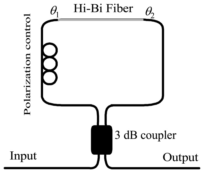
A standard Hi-Bi fiber loop mirror is shown in Figure 1. The Hi-Bi FLM integrates a 3 dB coupler which splits the input light into two counter propagating beams, which transverse the loop. They propagate through the Hi-Bi fiber with different velocity. Meanwhile, their individual polarization direction varies, and the two beams will interfere at the output port.
Figure 1.
Schematic of a Hi-Bi fiber loop mirror.
Therefore, the loop filter characteristic is similar to an unbalanced Mach-Zehnder. The phase difference (Δϕ) between the fast and slow beams that propagate in the Hi-Bi fiber is given by:
| (1) |
where β, L and λ are, the birefringence, the length of Hi-Bi fiber and the wavelength operation, respectively. The transmission spectrum (T) of the Hi-Bi fiber loop mirror is approximately a periodic function of the wavelength, namely:
| (2) |
where θ1 and θ2 are the angles between the light at the both end of the Hi-Bi fiber and the fast or slow axis of the Hi-Bi fiber, respectively, as shown Figure 1. The reflectivity response (R) of the Hi-Bi fiber loop mirror is given by, R=1-T. The wavelength spacing (Δλ) is inversely proportional to the length and the birefringence of the Hi-Bi fiber as follows [2]:
| (3) |
According to equation (3), the following conclusions can be drawn: for small wavelength spacing, a larger birefringence or a longer length of the Hi-Bi fiber is required. Also, this spectral characteristic is independent of the polarization state of the input light [15].
3. Characterization of Standard Hi-Bi Fibers Based Fiber Loop Mirror
3.1. Hi-Bi Fibers
Figure 2 shows the structure of standard Hi-Bi fibers. They are: a) elliptical core (e-core); b) D-type; c) PANDA; d) bow-tie and e) internal elliptical cladding (IEC). All these optical fibers are two-polarization modes and are classified as highly birefringent, due to the birefringence β > 10-5, when compared with standard single mode fibers that present low birefringence [2].
Figure 2.

Cross section of conventional Hi-Bi fibers: a) e-core, b) D-type fiber, c) PANDA, d) bow-tie and e) IEC.
The internal birefringence of Hi-Bi fibers can be produced by the geometrical effect (GE) of the core (for instance, elliptical core fiber (Fig 2.a) and D-type fiber (Fig 2.b)) or by the stress effect (SE) around the core (for instance, PANDA fiber (Fig 2.c), Bow-Tie fiber (Fig 2.d), and internal elliptical cladding fiber (Fig 2.e)). All these Hi-Bi fibers are commercially available and Table 1 lists standard parameters.
Table 1.
Typical parameters of standard commercial Hi-Bi fibers
| Type fiber | β (×10-4) | Lp (mm) | α (dB/km) | Company |
|---|---|---|---|---|
| e-core (48280-1550S-5) | 3.85 | 4.0 | ≤ 9 | KVH |
| D-type (205170-1550S) | 4.71 | 3.3 | ≤ 9 | KVH |
| PANDA (PM-1550-HP) | 3.3 | 4.65 | ≤ 1 | Thorlabs |
| Bow-tie (HB 1500) | 4.35 | 3.56 | <2 | Fibercore |
| IEC (3M FS-PM-7621) | 5.1 | 3.0 | 1 | 3M |
3.2. Strain and Temperature Characterization
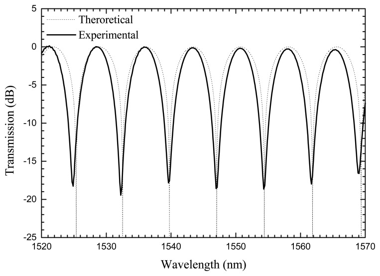
All these Hi-Bi fibers were inserted inside the fiber loop mirror and characterized when strain and temperature were applied. All fibers were characterized with coating (acrylate), due to their fragility. Figure 3 presents an experimental example of the transmission spectrum formed by the Hi-Bi FLM as well as the theoretical spectral response obtained using equation (2).
Figure 3.
Transmission spectra of the Hi-Bi FLM.
The experimental setup consisted in an optical broadband source, a FLM, containing a section of Hi-Bi PCF and an optical spectrum analyzer with a maximum resolution of 0.05 nm. The optical source was an Erbium-doped broadband source, with a central wavelength of 1550 nm and a spectral bandwidth of 100 nm. The Hi-Bi PCF FLM is formed by a 3 dB (2×2) optical coupler with low insertion loss, an optical polarization controller, and a Hi-Bi PCF section. For strain characterization, the sensing head was attached to a translation stage with a resolution of 1 μm. For temperature characterization, the Hi-Bi PCF was placed in a tubular oven, which permits a temperature reading to be set with an error smaller than 0.1 °C.
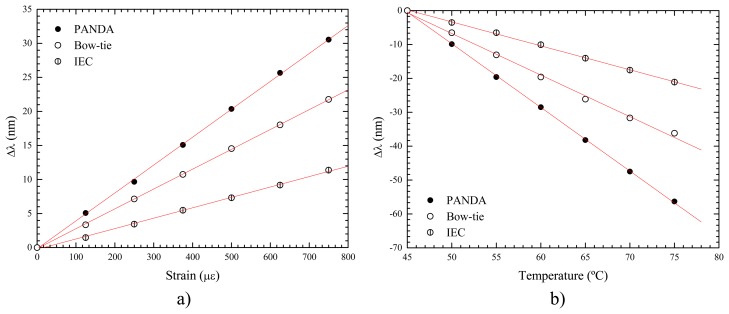
Figures 4a) and 4b) show the effect of strain and temperature on the spectral transfer function of the FLM with different types of Hi-Bi fibers based on the SE.
Figure 4.
a) Strain response and b) temperature response of Hi-Bi FLM with SE fibers
These fibers present positive strain sensitivities; when the applied strain increases, the path length increases, and therefore the fringe peak wavelength increases (the birefringence essentially does not change). On the other hand, when subjected to temperature, such fibers present negative temperatures sensitivities. In this case, the strongest effect arises from the birefringence change, which decreases with the increase of temperature. The PANDA fiber is more sensitive due to its birefringence created by the two big holes with the boron doped, when compared with the other SE Hi-Bi fibers [16].
The Hi-Bi FLM with Hi-Bi fiber produced by GE was also characterized. These Hi-Bi FLMs have a different response and present lower sensitivity for strain and temperature when compared with Hi-Bi FLMs implemented with SE fibers. Figure 5 a) and 5 b) present the strain and temperature characterization of Hi- Bi FLM structures incorporating e-core and D-type fibers. In this case, the Hi-Bi FLM with D-type fiber is more sensitive when compared with the Hi-Bi FLM with e-core fiber. The differences between the two Hi-Bi fibers are due to their different structures. While the birefringence in the D-type fiber arises from two factors (elliptical core and the cladding format), in the e-core fiber only the elliptical core is responsible for the birefringence.
Figure 5.
a) Strain response and b) temperature response of Hi-Bi FLM with GE fibers.
Table 2 summarizes the strain and temperature coefficient sensitivities of the FLM structure implemented with each type of fiber.
Table 2.
Strain and temperature coefficients for all Hi-Bi fiber loop mirrors.
| Type fiber | κε (pm/με) | κT (nm/°C) |
|---|---|---|
| PANDA | 41.2 | -1.9 |
| Bow-Tie | 28.8 | -1.23 |
| IEC | 15.4 | -0.7 |
| e-Core | -2.5 | -0.2 |
| D-type | -3.2 | -0.34 |
4. Characterization of Hi-Bi Photonics Crystal Fiber Based Fiber Loop Mirror
Photonics Crystal Fiber (PCF) is a new type of optical fiber that has emerged recently, which show very interesting guiding properties [17]. These fibers have an arrangement of microscopic air holes running along their length, and have the great advantage that by varying the size and location of the holes, the fiber mode shape, non-linearity, dispersion and birefringence can reach values that are not achievable in conventional fibers. Several authors have presented the PCF as a new and promising alternative solution for application in optical communication systems [18] and in optical fiber sensing [19]. In this type of fiber the internal birefringence is created by the GE. Applications combining the Hi-Bi PCF with the FLMs have been also presented, for instance, a Sagnac loop interferometer based on polarization maintaining photonic crystal fiber with temperature insensitivity [20, 21]. Yang et al have proposed a fiber Bragg grating sensor interrogation technique with temperature insensitivity by using a highly birefringent photonic crystal fiber Sagnac loop filter [22]. This device was also demonstrated as temperature-insensitive strain sensor or load sensor [23, 24]. Due to the properties of the uncoated Hi-Bi PCF fiber, its incorporation in fiber loop mirrors turns this structure insensitive to temperature variations when compared with the case of using standard Hi-Bi fibers. Actually, the Hi-Bi PCF loop mirror was characterized for two different cases, uncoated and coated. The results are different for each situation [25]. The acrylate material of the coating changes the strain and temperature sensitivities. This aspect can be very important in future applications, namely when special re-coatings are applied to create high sensitivity to chemical or biological parameters.
The experimental setup of a Hi-Bi PCF FLM sensing system is based on the one described in Figure 1 and consists in an optical broadband source, a fiber loop mirror containing a section of Hi-Bi PCF and an optical spectrum analyzer (OSA) with a maximum resolution of 0.05 nm. The optical source is an Erbium-doped broadband source, with a central wavelength of 1550 nm and a spectral bandwidth of 100 nm. The Hi-Bi PCF FLM is formed by a 3dB (2×2) optical coupler with low insertion loss, an optical polarization controller (PC) and a Hi-Bi PCF section. This Hi-Bi PCF (Thorlabs PM-1550-01) is a polarization maintaining PCF fiber containing two large holes, with a beat length smaller than 4 mm and an attenuation inferior to 1.0 dB/Km for a wavelength of 1550 nm (Figure 6).
Figure 6.

Photo of the Hi-Bi PCF fiber.
The diameters of the two holes are 4.5 μm and 2.2 μm, respectively, the pitch (spacing between holes) is 4.4 μm, and the diameter of the perforated region is 40 μm, while the fiber outer diameter is 125 μm. A low loss splice (∼2 dB) between SMF 28 from the optical coupler and the PCF was achieved.
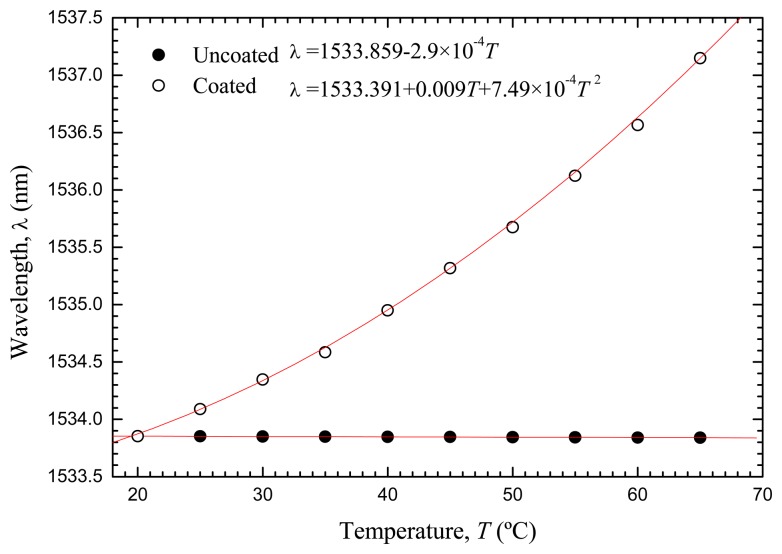
Figure 7 represents the evolution of the wavelength shift when temperature is applied in the situations of uncoated and coated Hi-Bi PCF. As can be observed, for the case of utilization of uncoated PCF the FLM structure was essentially insensitive to temperature variations (-0.29 pm/ °C). To explain this behavior, one has to bear in mind that the Hi-Bi PCF has an internal structure of pure silica with two air holes. Therefore, this single material composition is in the origin of the low temperature sensitivity. On the other hand, when the Hi-Bi PCF has an acrylate coating, a non-linear response to temperature was observed, surely a consequence of the non-linear temperature behavior of the acrylate polymer.
Figure 7.
Temperature response of the Hi-Bi PCF FLM.
For the case of applied strain, as expected the spectral response of the fiber configuration is similar for the cases on uncoated and coated Hi-Bi PCF. Table 3 summarizes the strain and temperature coefficients of the Hi-Bi PCF based fiber loop mirror.
Table 3.
Strain and temperature coefficients for the Hi-Bi PCF fiber loop mirror.
| Hi-Bi PCF | κε (pm/με) | κT (nm/°C) |
|---|---|---|
| Coated | 1.21 | 2.312 ≥ κT ≥ 2.306 |
| Uncoated | 1.11 | -2.9×10⁻⁴ |
5. Simultaneous Measurement using Hi-Bi Fiber Loop Mirrors
5.1. Hi-Bi FLM Combined with a Long Period Grating
In this section, we present a configuration for strain and temperature discrimination. The setup combines a long period grating (LPG) with a high-birefringence fiber loop mirror. Due to the opposite strain and temperature response of the Hi-Bi FLM when compared with the LPG, it is possible to obtain a sensing head for strain and temperature discrimination. The sensing head is based on the combination of a section of Hi-Bi fiber in series with a LPG inside the loop mirror, and uses the same set-up described earlier. The Hi-Bi fiber (3M FS-PM-7621) is a polarization maintaining (internal elliptical cladding) single mode optical fiber at 1550 nm, with a beat length of 1.6 mm at 633 nm and an attenuation of 1.0 dB/Km. The LPG, with a length of 20 mm, was fabricated in a Corning SMF-28 fiber by means of electric arc discharge with a period of 405 μm. During grating inscription, the fiber was under a tension of 5.1 grams and subjected to 48 arc discharges with 9 mA of current and 1 second of duration. The resulting resonance wavelength of the LPG was 1578 nm. With the polarization controller it was possible to optimize the Hi-Bi FLM for a wavelength of 1547 nm, with maximum loss of 25 dB. Figure 8 presents the spectral response of the resulting sensing head.
Figure 8.
Spectral response of a concatenated Hi-Bi FLM and LPG.
As indicated in Table 4, the strain and temperature sensitivity responses of the Hi-Bi FLM are opposite to those of the LPG. The range of temperature and strain for these measurements were respectively of 60 °C and 700 με [14]. As expected, the wavelength notch of the LPG presents a smaller variation to the change of these parameters when compared with the correspondent results for the Hi-Bi FLM [26].
Table 4.
Strain and temperature coefficients of the Hi-Bi PCF fiber loop mirror and LPG spectral features.
| κε (nm/με) | κT (nm/°C) | |
|---|---|---|
| LPG | -4.37×10⁻³ | 0.085 |
| Hi-Bi FLM | 29.84×10⁻³ | -0.55 |
This configuration setup allows different kinds of multi-parameter measurement by tailoring the LPG characteristics. For instance, it can be considered the measurement of the pairs (temperature, bending), (temperature, pressure) or (temperature, refractive index). In this latter case the LPG is simultaneously sensitive to refractive index and to temperature [27]; on the other hand, the segment of the Hi-Bi fiber is only sensitive to temperature.
5.2. Concatenated Hi-Bi Fiber Loop Mirrors
The concatenation of Hi-Bi FLMs has been demonstrated by Liu et al [28]. In this section, it is proposed and demonstrated an alternative configuration for simultaneous strain and temperature discrimination using two concatenated Hi-Bi FLMs [29]. The first Hi-Bi FLM contains a section of Hi-Bi PCF acting as a reference configuration since the 2nd section of the Hi-Bi fiber is the sensor part. The second Hi-Bi FLM contains a section of internal elliptical cladding (IEC) fiber with 400 mm length where strain (and also temperature) is applied. Figure 9 presents the spectral response of this concatenated structure when strain or temperature is applied.
Figure 9.
Spectral response of the concatenated FLMs, when strain is increased for constant temperature (spectral shift to longer wavelengths), .and when temperature is increased for constant strain (spectral shift to shorter wavelengths).
It shows that when strain is increased at constant temperature, the wavelength of the selected spectral peak increases and its optical power decreases. When temperature is increased under constant strain, the wavelength decreases and the optical power increases. The change in wavelength is due to the strain and temperature induced variations of the optical path length of the concatenated Hi-Bi FLM structure. On the other hand, the optical power variation is a result of the product of the individual transfer functions of the two FLMs.
Table 5 presents the coefficients of strain and temperature for the concatenated FLMs, which result from linear responses. For the temperature response, the sensing head has the opposite response when compared with the strain response. The high temperature sensitivity (0.96 nm/°C) can be explained by the effect of the internal stress of the IEC fiber that is created by the elliptical inner cladding, which has a different thermal expansion coefficient from the outer cladding. These measurements were performed in a range of 700 με at a fixed temperature and in a range of 18 °C for a specific applied strain.
Table 5.
Strain and temperature coefficients for the concatenated FLMs.
| κε i | κT i | |
|---|---|---|
| Wavelength | 11.43 pm/με | -0.96 nm/°C |
| Optical power | -4.62×10⁻³ με−1 | 0.64 °C-1 |
The sensor was characterized in strain and temperature and the rms resolutions were found to be ±21 με, and ±1.1 °C respectively. These results were obtained for these measurands, but the system can also be adapted to discriminate physical parameters such as pressure, torsion, curvature, and others that induce variations in the characteristics of the Hi-Bi fibers.
6. Chemical Etching in Hi-Bi Fiber Loop Mirrors
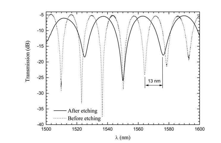
Chemical etching in high birefringence fiber loop mirrors has been also demonstrated [30]. The experimental set-up that consists of an optical broadband source, a fiber loop mirror, containing a section of Hi-Bi fiber and an optical spectrum analyzer with a resolution maximum of 0.1 nm. The optical source is an Erbium-doped broadband source, with a central wavelength of 1550 nm and a spectral bandwidth of 100 nm, and has the purpose of characterizing the fiber loop mirror. The Hi-Bi FLM is formed by a 3 dB (2 × 2) optical coupler with low insertion loss, an optical polarization controller and a Hi-Bi fiber section. This Hi-Bi fiber section is a bow-tie fiber for a wavelength of 1550 nm with a beat length of <5 mm and an attenuation of <0.2 dB Km−1. The Hi-Bi fiber was placed in a container with hydrofluoric acid, and in order to investigate the changes in the birefringence properties of the bow-tie fiber, the optical spectral response was analyzed. Due to etching, the stress distribution of the fiber is changed and the birefringence of the bow-tie fiber was also changed, i.e., the birefringence decreased and the wavelength spacing between minima increased. In Figure 10, it is compared the two spectral responses before and after etching when the birefringence is reduced to half of the initial values.
Figure 10.
Spectral response of the Hi-Bi FLM before and after chemical etching.
This effect created by chemical etching can be important in optical sensing, namely to increase the resolution of the Hi-Bi fiber loop mirror when used for refractive index measurements.
7. Refractive Index Measurement
In this section we present a Hi-Bi fiber loop mirror using D-type fiber for refractive index measurement. The D-type fiber used has a length of 300 mm and an elliptical core surrounded by a cladding with a D-shape. In the smallest distance the core is very close from the surrounding-medium (13.5 μm), but it was further reduced to ≈ 8 μm applying chemical etching using hydrofluoric acid (HF at 40%). This chemical etching allowed to increase the external evanescent field, therefore enhancing the sensitivity to the external refractive index when the D-type fiber is immersed in liquids. Before chemical etching, the period of the channeled spectrum was ≈ 17 nm; after chemical etching this period increased 1 nm, corresponding to a birefringence variation of ≈ 0.26×10⁻⁴. To calibrate the sensing head to measure refractive index, the D-type fiber inside the FLM was immersed in samples of water combined with different percentages of ethylene glycol. The liquid samples were characterized through an Abbe refractometer using the sodium D line (589 nm). Because this sensing head was operated at 1550 nm, it was necessary to use the Cauchy equation with the respective coefficient [31]. The relationship between the wavelength variation and the refractive index is presented in Figure 11.
Figure 11.
Refractive index measurement using D-type fiber in a fiber loop mirror.
A linear fit with a slope of -10.8/0.07 nm/RIU was obtained. The negative slope behavior is a result of the effect of the refractive index of the liquids in the fiber birefringence, changing the fast and slow axis properties. This result shows great potential in several applications, particularly to monitor chemical and biological parameters in natural environments.
8. Concluding Remarks
This paper reviewed recent advances in high-birefringence fiber loop mirror based sensors. This type of interferometric configuration is not itself a new concept; however, with the emergence of novel fibers (for instance: photonics crystal fibers), this structure has been the focus of intense R&D in last years. The work presented here compares the performance of fiber loop mirrors containing several conventional Hi-Bi fibers and Hi-Bi PCF fibers when subjected to strain and temperature. Strain sensing with temperature insensitivity, simultaneous measurement of physical parameters, chemical etching and refractive index measurement were topics addressed in this review. In view of recent trends, it is expectable, in the near future, novel developments relying on the fiber loop mirror configuration, most of them triggered by the new opportunities associated with biochemical sensing and environmental monitoring.
References and Notes
- 1.Mortimore D. Fiber loop reflectors. Journal of Lightwave Technology. 1988;6:1217–1224. [Google Scholar]
- 2.Noda J., Okamoto K., Sasaki Y. Polarization-maintaining fibers and their applications. Journal of Lightwave Technology. 1986;4:1071–1088. [Google Scholar]
- 3.Culshaw B. The optical fibre Sagnac interferometer: an overview of its principles and applications. Measurement Science and Technology. 2006;17:R1–R16. [Google Scholar]
- 4.Kim S., Kang J. U. Polarization-independent “figure-eight” birefringent Sagnac variable comb-filter/attenuator. IEEE Photonics Technology Letters. 2004;16:494–496. [Google Scholar]
- 5.Li S., Chiang K. S., Gambling W.A. Gain flattening of an erbium doped fiber amplifier using a High-Birefringence fiber loop mirror. IEEE Photonics Technology Letters. 2001;13:942–944. [Google Scholar]
- 6.Dong X. P., Li S., Chiang K. S., Ng M. N., Chu B. C. B. Multiwavelength erbium doped fiber laser based on a high-birefringence fiber loop mirrors. Electronics Letters. 2000;36:1609–1610. [Google Scholar]
- 7.Chung S., Yu B.-A., Lee B. Phase response design of a polarization-maintaining fiber loop mirror for dispersion compensation. IEEE Photonics Technology Letters. 2003;15:715–717. [Google Scholar]
- 8.Campbell M., Zheng G., Holmes-Smith A. S., Wallace P. A. A. Frequency-modulated continuous wave birefringent fiber-optic strain sensor based on a Sagnac ring configuration. Measurement Science Technology. 1999;10:218–224. [Google Scholar]
- 9.Starodumov A. N., Zenteno L.A., Monzon D., De La Rosa E. Fiber Sagnac interferometer temperature sensor. Applied Physics Letters. 1997;70:19–21. [Google Scholar]
- 10.Bo D., Qida Z., Feng L., Tuan G., Lifang X., Shuhong L., Hong G. Liquid-level sensor with a high-birefringence-fiber loop mirror. Applied Optics. 2006;45:7767–7771. doi: 10.1364/ao.45.007767. [DOI] [PubMed] [Google Scholar]
- 11.Liu Y., Liu B., Feng X., Zhang W., Zhou G., Yuan S., Kai G., Dong X. High-birefringence fiber loop mirrors and their applications as sensors. Applied Optics. 2005;44:2382–2390. doi: 10.1364/ao.44.002382. [DOI] [PubMed] [Google Scholar]
- 12.Chung S., Kim J., Yu B.-A., Lee B. A Fiber Bragg grating sensor demodulation technique using a polarization maintaining fiber loop mirror. IEEE Photonics Letters. 2001;13:1343–1346. [Google Scholar]
- 13.Frazão O., Marques L. M., Baptista J. M. Fiber Bragg grating interrogation based on high-birefringence fiber loop mirror for strain-temperature discrimination. Microwave and Optical technology Letters. 2006;48:2326–2328. [Google Scholar]
- 14.Frazão O., Marques L. M., Santos S., Baptista J. M., Santos J. L. Simultaneous measurement for strain and temperature based on a long period grating combined with a high-birefringence fiber loop mirror. IEEE Photonics Technology Letters. 2006;18:2407–2409. [Google Scholar]
- 15.Fang X., Claus R. O. Polarization-independent all-fiber wavelength-division multiplexer based on Sagnac interferometer. Optics Letters. 1995;20:2146–2148. doi: 10.1364/ol.20.002146. [DOI] [PubMed] [Google Scholar]
- 16.Zhang F., Lit J. W. Y. Temperature and strain sensitivity measurements of high-birefringent polarization-maintaining fibers. Applied Optics. 1993;32:2213–2218. doi: 10.1364/AO.32.002213. [DOI] [PubMed] [Google Scholar]
- 17.Knight J. C. Photonic crystal fibers. Nature. 2003;424:847–51. doi: 10.1038/nature01940. [DOI] [PubMed] [Google Scholar]
- 18.Broderick N. G. R., Monro T. M., Bennett P. J., Richardson D. J. Nonlinearity in holey optical fibers: measurement and future opportunities. Optics Letters. 1999;24:1395–1397. doi: 10.1364/ol.24.001395. [DOI] [PubMed] [Google Scholar]
- 19.Monro T. M., Belardi W., Furusawa K., Baggett J. C., Broderick N. G. R., Richardson D. J. Sensing with microstructured optical fibers. Measurement Science and Technology. 2001;12:854–858. [Google Scholar]
- 20.Kim D.-H., Kang J. U. Sagnac loop interferometer based on polarization maintaining photonic crystal fiber with reduced temperature sensitivity. Optics Express. 2004;12:4490–4495. doi: 10.1364/opex.12.004490. [DOI] [PubMed] [Google Scholar]
- 21.Zhao C-L., Yang X., Lu C., Jin W., Demokan M. S. Temperature-insensitive interferometer using a highly birefringent photonic crystal fiber loop mirror. IEEE Photonics Technology Letters. 2004;16:2535–2537. [Google Scholar]
- 22.Yang X., Zhao C-L., Peng Q., Zhou X., Lu C. FBG sensor interrogation with high temperature insensitivity by using a HiBI-PCF Sagnac loop filter. Optics Communications. 2005;250:63–68. [Google Scholar]
- 23.Tam H.Y., Dong X. Temperature-insensitive strain sensor with polarization-maintaining photonics crystal fiber based on Sagnac interferometer. Applied Physics Letters. 2007;90:151113:1–151113:3. [Google Scholar]
- 24.Frazão O., Marques L. M., Marques J., Baptista J. M., Santos J. L. Temperature independent strain/load sensor using a highly birefringent photonic crystal fiber fibre loop mirror. Third European Workshop on Optical Fibre Sensores, Proceedings of SPIE; 2007. pp. 66190Y-1–66190Y-4. [Google Scholar]
- 25.Frazão O., Baptista J. M., Santos J.L. Temperature-independent strain sensor based on a Hi-Bi photonic crystal fibre loop mirror. IEEE Sensors Journal. 2007;7:1453–1455. [Google Scholar]
- 26.Bhatia V. Applications of long-period gratings to single and multi-parameter sensing. Optics Express. 1999;4:457–466. doi: 10.1364/oe.4.000457. [DOI] [PubMed] [Google Scholar]
- 27.James S. W., Tatam R. P. Optical fibre long-period grating sensors: characteristics and application. Measurement Science Technology. 2003;14:R49–R61. [Google Scholar]
- 28.Liu Y., Zhao Q., Zhou G., Zhang H., Chen S., Zhao L., Yao Y., Guo P., Dong X. Study on an optical filter constituted by concatenated Hi-Bi fiber loop mirror. Microwave and Optical Technology Letters. 2004;43:23–26. [Google Scholar]
- 29.Frazão O., Baptista J. M., Santos J.L. Strain and temperature discrimination using concatenated Hi-Bi fiber loop mirrors. IEEE Photonics Technology Letters. 2007;19:1260–1262. [Google Scholar]
- 30.Frazão O., Guerreiro A., Santos J. L., Baptista J. M. Birefringence monitoring of a Hi-Bi fibre under chemical etching through a fibre loop mirror. Measurement Science Technology. 2007;18:81–83. [Google Scholar]
- 31.Pereira D.A., Frazão O., Santos J.L. Fiber Bragg grating sensing system for simultaneous measurement of salinity and temperature. Optical Engineering. 2004;43:299–304. [Google Scholar]


