Abstract
This paper undertakes the modular design and development of a minimally invasive surgical manipulator for MRI-guided transperineal prostate interventions. Severe constraints for the MRI-compatibility to hold the minimum artifact on the image quality and dimensions restraint of the bore scanner shadow the design procedure. Regarding the constructive design, the manipulator kinematics has been optimized and the effective analytical needle workspace is developed and followed by proposing the workflow for the manual needle insertion. A study of the finite element analysis is established and utilized to improve the mechanism weaknesses under some inevitable external forces to ensure the minimum structure deformation. The procedure for attaching a sterile plastic drape on the robot manipulator is discussed. The introduced robotic manipulator herein is aimed for the clinically prostate biopsy and brachytherapy applications.
I. Introduction
According to the American Cancer Society prostate cancer is placed second in rank among the cancer categories with high incidence in the United States. In 2012 about 241,740 new cases will be diagnosed and 28,170 men will die from this disease [1]. One of the typical diagnostic approaches for the prostate cancer is the manual transperineal prostate biopsy [2, 3]. If the result is positive, many patients choose brachytherapy as minimally invasive treatment. These procedures, biopsy and brachytherapy, require prostate percutaneous interventions manually performed under ultrasound imaging. A better alternative to ultrasound is the magnetic resonance imaging (MRI). Since the MRI provides high levels of contrast resolution and owns the feasibility to image in any plane, it can be widely used in the surgical interventions. Manually executed percutaneous interventions have lack of precision and repeatability. One promising approach for solving these deficiencies is the robot assisted MRI-guided prostate percutaneous interventions.
For those designed mechanisms to be applicable in the MRI environment and not interfere with the imaging quality of the MRI scanner, all robot components are required to be constructed with the nonmagnetic and dielectric materials. This could significantly influence dimension and stiffness of the system when compared with the metal materials, and hence, this demands much attention in the design process. There are numerous robotic systems developed to accurately place the needle inside the prostate gland in two different fashions: manually [4, 5] and automatically [6, 7, and 10].
A comprehensive review of the MRI-compatible robotic/mechatronics systems is studied in [8]. In [9] an overview of the minimally invasive robotic surgery is carried out and its historical developments are studied. A fully automated robot for the transperineal prostate interventions and fully MR imaging compatible is introduced in [10]. The corresponding robot is sought to be performed for the fully automated brachytherapy seed placement under a closed MR scanner.
Due to the restriction of the MRI-compatibility, there are few choices for the actuators which can be mainly categorized as piezoelectric and pneumatic motors. Pneumatic actuators have a great compatibility with the MRI environment since ferrous material or electric component is not required. Fischer et al. have developed a pneumatically computer-integrated robotic mechanism with 6 degrees-of-freedom (DOF) for the transperineal prostate needle placement in the closed-bore MRI scanner [11]. A new 4-DOF needle guided robotic system is designed for the prostate biopsy and brachytherapy planning [12]. There is a limited workspace in the designed robot in which a simple external damping mechanism implementing a timing belt is considered to overcome this problem and the new workspace is optimized. For evaluating the pneumatically actuated robotic system, some experiments are conducted on a prostate phantom and patient mock-up procedures. Some noticeable position errors were observed mainly because of the inaccurate control gain, registration value and needle bending that need the robot to be mechanically calibrated and precisely registered inside the scanner [13].
A robotic assistance for the MRI-guided cryotherapy is developed to help radiologist for precisely place the needle during the insertion. This is an alternative approach between the fully automated and manual insertion to insert multiple needles [14]. Design and kinematics of a 5-DOF hybrid-driven MRI-compatible robot is presented in [15] in which the system consists of the pitch/lift module, the yaw/horizontal module, and the insertion module which are linked by the parallel and serial mechanisms. The corresponding robot workspace is large enough but the size of the robot needs to be optimized and reduced. Su et al. have conceptually designed a 4-DOF Cartesian MRI-guidance surgical manipulator which is developed for the prostate brachytherapy and neurosurgery applications. This robot takes advantage of a parallel mechanism and is compact enough to be implemented with the closed-bore MRI scanner [16].
In this paper, we present a 4-DOF surgical manipulator specifically aimed for the clinically prostate biopsy and brachytherapy interventions. This system comprises of two coupled front and rear planar trapezoid-shape linkages which replaced the triangle-shape stages considered in earlier models [12, 13]. This modular design can convert the lateral displacement into the vertical motion while the robot placement error for the needle is expected to be less than 0.5 mm in air. Specifying the constrains governing on the system such as the required workspace, low friction, high stiffness, robust dynamic and maneuverability, and by accounting for the kinematics optimization, the optimum dimensions of the front and rear stages are determined through a trial and error procedure. In the first prototype of the robot design scheme, the needle driver support is placed on top of the robot for the manual needle placement while the automatic needle positioning is planned as the next stage of this work. This manipulator is designed in such a way to span a region noticeably larger than the prostate size, which this facilitates the system to be eventually practical in the clinical procedures. For this purpose, the kinematics derivation and workspace analysis are established. It is essential to ensure the stiffness of the mechanical structure since any small structural deformation can propagate into the whole system and bring significant amount of errors into the needle tip displacement. Therefore, a finite element analysis is carried out and the weak points of the structure are modified and strengthened. Unlike the pneumatically actuated robotic system, the current system is planned to benefit from the piezoelectric actuators which in terms of the design concern, this can considerably reduce the overall size of the robot. Finally, the sterilization and workflow procedures are carefully elaborated to make this system clinically applicable.
II. Surgical Manipulator Development for Needle Placement
A. Mechanical Design and Requirements
The objective of this robotic manipulator is in-vivo manually guiding the 18G needle into the human prostate tissue inside the closed-bore MAGNETOM Verio 3T MRI scanner made by the Siemens® Co. with the anticipated error less than 0.5 mm in air.
Based on different human anatomical data, the average size of the prostate gland diameter is about 50 mm. Because of the patient body variability we have decided to cover a circle with 70 mm diameter. With the patient in the supine position and legs in the semi-lithotomy configuration, based on our previous experiments, the prostate center is located around 130 mm from the patient bed, for median size patients (http://msis.jsc.nasa.gov/sections/section03.htm). For bigger size patients the gland center could be at around 160–165 mm from the patient bed. In order to account for the gland vertical position variability we decided to cover an oval-shaped workspace with the extreme potions in the vertical direction 95 mm and 200 mm, respectively (Fig. 1).
Figure 1.
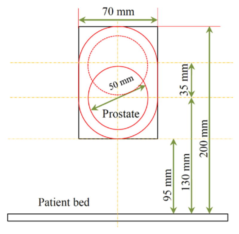
Desired worksapce for the needle positioning.
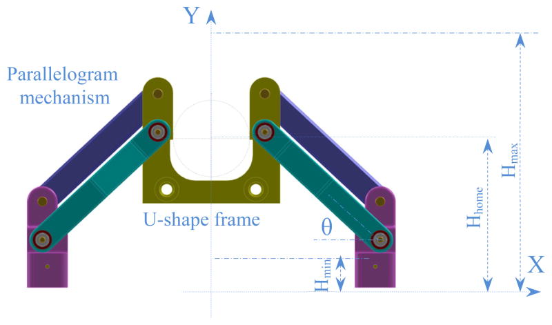
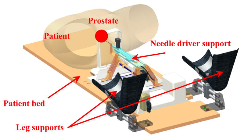
Due to the restriction of the scanner bore dimension with 70 cm diameter, we are only allowed to move about 70 mm (±35 mm) in the lateral positions. Accounting for the above mentioned considerations, the robot manipulator consists of three major parts: front trapezoid stage, rear trapezoid stage, and needle driver support. The novel concept of using two front and rear trapezoid stages makes the robot suitable for the angulated needle placement with the range of 35 mm in the lateral motion. In addition, the distance between the front and rear stages can orientate the needle 10° in the horizontal plane. Preserving the same concept, maximum 10° angulation can be produced in the vertical plane. However, in the workspace boundary there is only 10° angulation toward the inside and there is no need to orientate the needle outside the workspace. By taking friction into account, each trapezoid stage is desired to move in the range of 25° ≤ θ ≤ 75°. It makes the structure more difficult to move when going below 25° while being over 75° may result in an unstable stage under some lateral forces. Figure 2 shows the front trapezoid stage and Fig. 3 depicts the 3D CAD model of the patient suite with the proposed manipulator and needle driver module.
Figure 2.
Parallel and planar front trapezoid stage (and mostly similar to the rear one) with the extreme and home positions.
Figure 3.
3D CAD model of the patient suite with 4-DOF manipulator and integrated needle driver support.
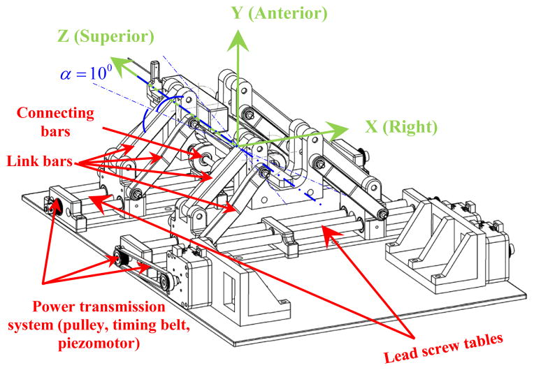
In the previous model of the robot [12, 13], the needle axis was defined by two spherical joints (front and rear) connected through one rigid bar. This way was possible to control the needle (and bar) orientation without controlling its rotation around the needle axis. In the current parallel mechanism two U-shape frames and four parallelogram mechanisms are employed for eliminating this issue. The front and rear stages (each one consisting of a U-shape frame and two parallelogram mechanisms) are mounted on two customized lead screw tables. The front U-shape frame has two ball and socket joints connected through two rigid bars with two spherical joints attached into the rear U-shape frame. The needle driver support is connected to the rigid bars by two sets of spherical joints. In such arrangement the needle axis is parallel and always between the connecting bars. Moving the front stage relatively to the rear one it is possible to control the needle (and bars) orientation. Needle axial rotation is controlled by rotating the needle relatively to the plane defined by the two connecting bars axes.
B. Kinematics Derivation
Each front and rear trapezoid stage in the vertical plane has 2-DOF and their combination generates a 4-DOF mechanism of which could be used for the needle orientation in the X-Y and X-Z planes (Figs. 4 and 5). In Fig. 4 the equivalent kinematic diagram of the 4-DOF robot manipulator is shown. The front and rear stages have similar kinematics arrangement and their coordinate systems are assigned such that they are in accordance with the coordinate system in the MRI scanner for registration.
Figure 4.
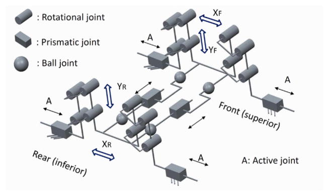
Equivalent kinematic diagram of the robot manipulator with 4-DOF.
Figure 5.
Defined XYZ coordinate system for the parallel surgical manipulator.
Figure 5 illustartes the XYZ coordiante system assigned on the robot manipulator. In Fig. 6 the kinematics parameters of the front and rear trapezoid stages are displayed. Notations 0 < x1f, x1r ∈ ℜ1 <200 and −200 < x2f, x2r ∈ ℜ1 < 0 are the positions of the carriages, and subscripts “f”, “r” implying the front and rear states, respectively. The front and rear stages are responsible for creating the position and orientation of the needle driver support. This motion can be a pure translation, rotation or a combination of these two types of motion. The position of point “N” (Fig. 6) can be expressed as:
| (1) |
where denote the coordinates of point “N” along the needle direction traveling through the front U-shape frame.
Figure 6.
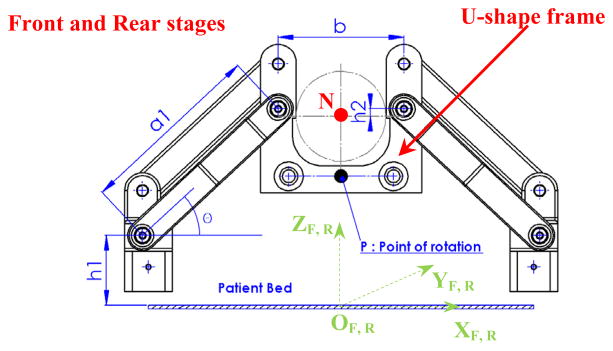
Front and rear trapezoid mechanisms with the relevant coordinate systems and corresponding kinematic parameters.
In Eq. (1), h1 denotes the distance between the center of the rotation joint of the carriage and the x axis and h2 is the distance between the needle axis and center of the lower hole of the U-shape frame; b is the horizontal distance between the center of the left and right holes of the U-shape frame, a1 is the length of the middle/side bar, and subscript i denotes the front and rear stages.
In order to achieve the desired workspace, it is essential that the needle can cover a wider area than the prostate gland size. In order to have an agreeable coverage in the vertical direction, the link bars need to be long enough but since the scanner bore size is confined (70 cm diameter), this dictates some restrictions on the kinematics design. Therefore, a kinematics optimization approach is established to find the optimum values of the parameters. In the constructed robot manipulator, the corresponding parameters are determined as: a1 = 124 mm; b = 84 mm; h1 = 50.2 mm; h2 = 5 mm. In addition, the distance between the front stage and the fiducial marker frame is 120 mm and the distance between the front and rear stages is chosen as 220 mm.
For the angulation of the needle driver support, there is a point of rotation which is called point “P” and two angles can be defined as: α, β (Figs. 5 and 7) to be obtained in the following manner:
| (2) |
where d is the distance between the front and rear stages.
Figure 7.
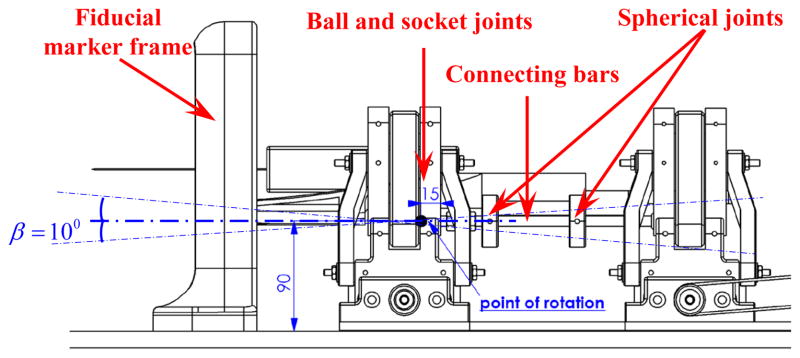
Side view of the robot manipulator, position of the rotation point “P” for the needle driver support.
C. Robot Analytical Workspace
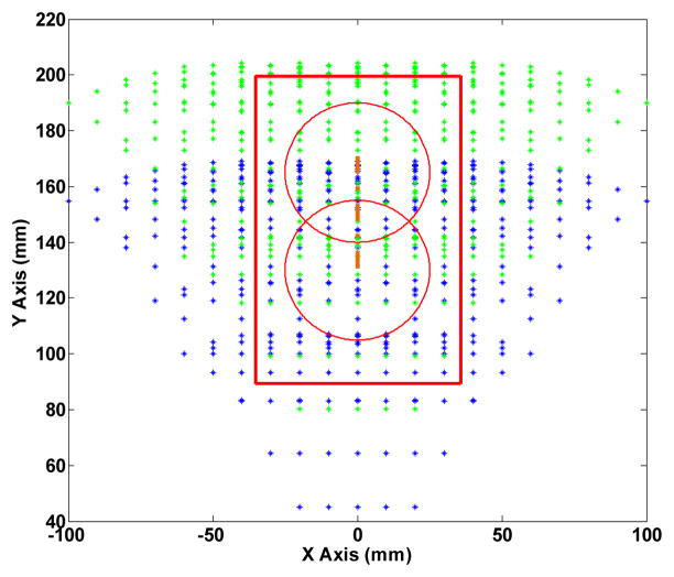
Due to the restriction of the robot size operating in the MRI scanner, it is challenging to explore a way for approaching the desired workspace introduced in Fig. 1. To this end, we have designed the needle driver in such a way the surgeon can insert the needle in two different positions being 35 mm off each other in the vertical direction. In this case, depending on the size of the patient body or the position of the prostate in the perineum, the surgeon may decide in which position he/she can manually drive the needle.
Figure 8 displays the analytical workspace of the robot manipulator in which the home position is defined at 130 mm. The red circles outline the prostate boundary (depending on the position of the patient’s prostate) while by shifting the needle 35 mm up, a larger workspace is accessible.
Figure 8.
Analytical workspace of the front and reas stages. Red circle implies the prostate gland for two different needle positions with 35 mm offset.
III. Finite Element Analysis and Structure Stiffness Assurance
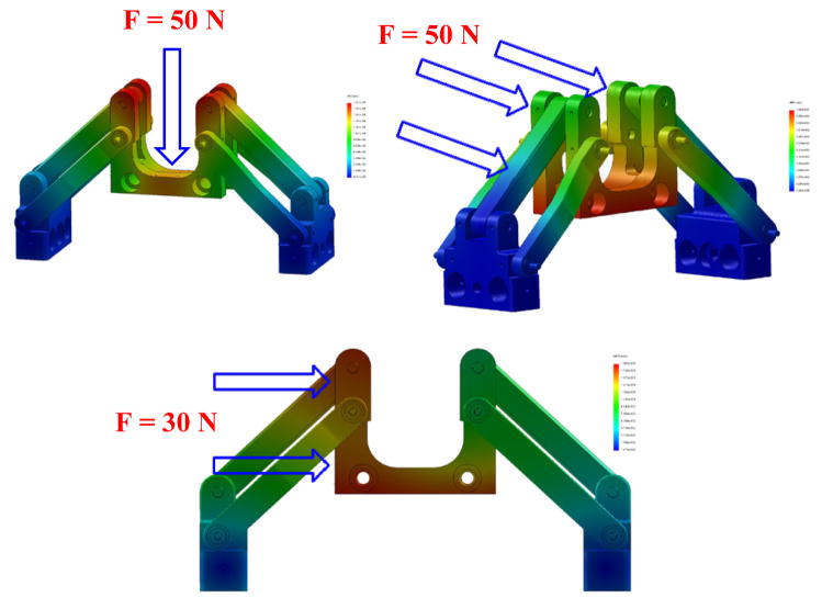
For a robot manipulator to be clinically approved and applied for in-vivo operations there are numerous factors which need to be investigated, determined and modified, if required. The most important aspect is to ensure that the designed mechanism has the highest precision for the needle insertion task. In order to warrant this, it is required that the mechanism preserves its stiffness in a satisfactory form against some various applied forces and torques exerting on that. To this end, determining the weak points of the designed mechanism where more stress concentration are present, has helped us to improve those points and reinforce the structure which consequently could result in less deflection. We have used the finite element analysis (FEA) for the stress study of the mechanism and Figs. 9 and 10 correspond to the FEA results for the needle driver support and the front trapezoid stage. It is observed that after modifying the needle driver support, the maximum deflection at the tip under 1 N (the maximum force to bend 18G biopsy needle at 45°) vertical force is about 0.11 mm resembling the force exerted by the surgeon by pushing and holding down the needle of the biopsy gun (for manual insertion). For the automatic insertion, it is crucial to consider the effects of the reaction of the needle while inserting into the tissue as well as the rod bars linking the front and rear stages. Therefore, in the similar way, the maximum deflections of the front stage (mostly similar to the rear one) are obtained about 0.1 mm under the 50 N frontal force and 0.18 mm under the 30 N lateral force.
Figure 9.
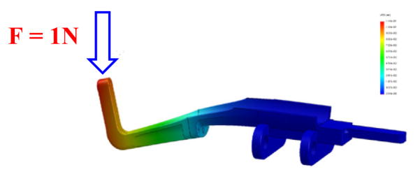
FEA of the needle driver support under the normal force at the tip result in 0.11 mm deflection.
Figure 10.
Front trapezoid stage under various loads: 1) vertical force (50 N), max. deflection about 0.19 mm (top); 2) frontal force (50 N), max. deflection about 0.1 mm (middle); and 3) lateral force (30 N), max. deflection about 0.18 mm (bottom).
On the other hand, by taking into account that the needle driver support is placed on top of the trapezoid stage, the same force plus additional forces are applied on the stage mainly arising from the plastic drape, contact of the surgeon’s hand, etc. For this reason, we considered 50 N vertical force applied on the front trapezoid stage and the maximum deflection observed is about 0.19 mm. All simulations results are executed with the Ultem™ 1000 for the plastic parts and brass alloy 385 for the rods and screws.
This study can assure us by having the kinematically optimized structure which can fit inside the 3T MRI scanner and ergonomic shape to be compatible with the patient anatomy and surgeon’s convenience, there would be the minimum deformation for the mechanism and maximum precision for the needle insertion procedure. It is essential to comprehend that any structural deformation can propagate in the needle tip position that must be accounted for from the beginning.
IV. Robot Sterilization and Clinical Workflow
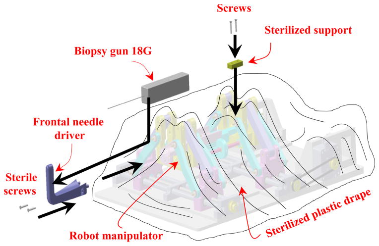
In the robot manipulator design procedure, we have considered capabilities to be fully sterilizable and ready for the clinical operations. The current prototype is comprised of two main parts: sterilizable and non-sterilizable components. As seen in Fig. 11, the main part of the robot is non-sterilizable and needs be covered and enfolded by a sterile plastic drape. In the manual driven process, in order to ease the insertion procedure of the needle (biopsy gun) into the needle driver support by the surgeon, we have intentionally designed the needle driver support in two major parts: sterilizable (frontal) and non-sterilizable (main) parts which are covered under the sterilized plastic drape. Since the needle driver support is made of different bodies, we investigated the effect of its discontinuity by implementing the FE analysis as depicted in Fig. 9. This can ensure there is the minimum deflection by applying the vertical force in which our initial design was modified according to this fact. After enclosing the robot, power transmission system, and the piezomotors by the plastic drape, the frontal part of the needle driver support can be guided and mounted into the main part of the needle driver support by two sets of screws (with a sterile screwdriver) considered for this reason based on the workflow as shown in Fig. 11.
Figure 11.
Procedure of the needle driver support installation after attaching the sterile plastic drape on the robot.
Once the plastic drape is placed on the robot, the sterilized support (Fig. 11) can be guided by another two sets of screws to fix the plastic drape securely to the robot at the rear side. After this stage and placing the patient in the scanner bore in the supine position, we put the robot manipulator on the patient bed next to the patient perineum and fiducial marker frame (Fig. 7). This process is followed by performing the MR scanning for needle targeting confirmation. The final stage is inserting the biopsy gun into two different holes on the frontal part of the needle driver support depending on the place of the prostate which is determined by the surgeon.
V. Current Implementation of the Surgical Manipulator
The initial design module of the robot manipulator is aimed for the manual needle insertion but also for the automatic insertion which will be achieved in the next stage of this project. Furthermore, the current modular design has the capability to be applied in the brachytherapy planning as well as the biopsy percutaneous interventions. In Fig. 12, the current implementation of the embodied robot manipulator for the prostate biopsy intervention is illustrated. Actuation mechanism for this 4-DOF manipulator is planned to be supported by 4 piezomotors (MRI-compatible) of which a representative view of only one motor and its location along with the power transmission system is shown in Fig. 12(a). Owing to this fact, the overall length of the robot is relatively reduced in comparison with the pneumatic versions of the robot manipulator [12, 13, and 17].
Figure 12.
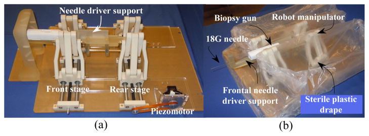
Robot manipulator embodiment (a), sterile plastic drape on the robot (b).
Clinical workflow and sterilization considerations are some of those essential stages which must be investigated in the design outline of the system. As explained earlier in Fig. 11, as the first step, the robot manipulator is completely enclosed with a sterile plastic drape as depicted in Fig. 12 (b). The sterilized frontal section of the needle driver must then be attached to the main needle driver support by using two sets of the sterile plastic screws.
Figure 13 demonstrates the position of the robot manipulator with respect to a volunteer’s perineum. In the current view, the robot is in the home position with respect to the patient’s prostate, while the patient is placed in the supine position. In the experimental evaluation of the system, the overall dimension of the robot has been examined resulting in a suitable ergonomic compatibility with the patient body and the proper accessibility of the biopsy gun. Under such circumstances, the surgeon is able to facilitate the needle insertion procedure more conveniently.
Figure 13.
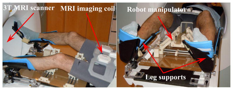
Evaluation of the robot manipulator implementation on a volunteer for transperineal prostate intervention.
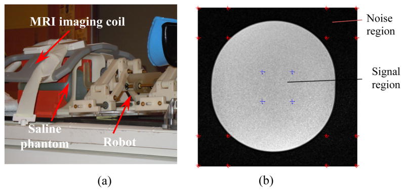
The preliminary evaluation of the robot signal-to-noise ratio (SNR) was done inside a 3T MRI scanner (MAGNETOM Verio, Siemens® Co). Figure 14 (a) shows the SNR experiment setup. The amount of the SNR degradation is a measure to identify the effects of robot presence on the image quality. The mean value of the SNR degradation normalized by the baseline is obtained as 6.37% for the case of with and without presence of the robot inside the scanner, for T2-weight Turbo Spin Echo sequences (Fig. 14 (b)).
Figure 14.
MRI SNR preliminary evaluation: experimental setup (a), example of T2 phantom image for the SNR test (b) – image size 320×320, image center 160, 160, region of interest size 30×30.
VI. Conclusion
In this paper, an MRI-compatible surgical manipulator for the minimally invasive prostate percutaneous intervention was designed and developed. This 4-DOF robot was built of two front and rear parallel trapezoid stages possessing each 2-DOF to create the necessary translational and rotational motions for the needle driver support which was mounted on it. The needle driver support was arranged to link the front and rear stages with two sets of axial ball and socket joints and two sets of spherical joints. Due to the scanner geometry restrictions the robot manipulator’s constructive design was optimized and the optimum kinematics parameters were obtained. The workspace of the needle mounted on the robot manipulator was able to span a large area of the perineum to ensure the prostate gland is always accessible by the surgeon. In order to ensure the stiffness of the structure for the needle and automatic needle insertion (as the future feature), the finite element analysis was executed under some different conditions and the corresponding design was improved at the weak points. Another aspect of the constructive design was implementing some arrangements for the sterilization procedure. In this consideration, the frontal part of the needle driver support could be connected to the main part of the needle driver with minimum effort and time such that this procedure was expected to be repeatable for numerous clinical operations. The current developed surgical manipulator is mainly planned to be clinically implemented in MRI-guided prostate interventions.
Footnotes
Supported by the National Institute of Health under grant No. R01CA111288.
Contributor Information
Sohrab Eslami, Laboratory for Computational Sensing and Robotics (LCSR) at the Johns Hopkins University, Baltimore, MD, USA.
Gregory S. Fischer, Automation and Interventional Medicine (AIM) Laboratory in the Department of Mechanical Engineering, Worcester Polytechnic Institute, Worcester, MA, USA.
Sang-Eun Song, Department of Radiology, Brigham and Women’s Hospital and Harvard Medical School, Boston, MA, USA.
Junichi Tokuda, Department of Radiology, Brigham and Women’s Hospital and Harvard Medical School, Boston, MA, USA.
Nobuhiko Hata, Department of Radiology, Brigham and Women’s Hospital and Harvard Medical School, Boston, MA, USA.
Clare M. Tempany, Department of Radiology, Brigham and Women’s Hospital and Harvard Medical School, Boston, MA, USA
Iulian Iordachita, Laboratory for Computational Sensing and Robotics (LCSR) at the Johns Hopkins University, Baltimore, MD, USA.
References
- 1.American Cancer Society. Prostate Cancer. 2012 http://www.cancer.org/Cancer/ProstateCancer/DetailedGuide/prostate-cancer-key-statistics.
- 2.D’Amico AV, Tempany CM, Cormack R, Hata N, Jinzaki M, Tuncali K, Weinstein M, Richie J. Transperineal magnetic resonance image guided prostate biopsy. J Urol. 2000;164(2):385–387. [PubMed] [Google Scholar]
- 3.Hata N, Jinzaki M, Kacher D, Cormack R, Gering D, Nabavi A, Silverman SG, D’Amico AV, Kikinis R, Jolesz FA. MR imaging-guided prostate biopsy with surgical navigation software: device validation and feasibility. Radiology. 2001;220:263–268. doi: 10.1148/radiology.220.1.r01jl44263. [DOI] [PubMed] [Google Scholar]
- 4.Fischer GS, DiMaio SP, Iordachita I, Fichtinger G. Robotic assistant for transperineal prostate interventions in 3T closed MRI. Proc 10th Int Con Med Image Comput and Comput Assis Inter – MICCAI, Part I. 2007;4791:425–33. doi: 10.1007/978-3-540-75757-3_52. [DOI] [PubMed] [Google Scholar]
- 5.Lagerburg V, Moerland MA, van Vulpen M, Lagendijk JJW. A new robotic needle insertion method to minimize attendant prostate motion. Radiotherapy and Oncology. 2006;80:73–77. doi: 10.1016/j.radonc.2006.06.013. [DOI] [PubMed] [Google Scholar]
- 6.van den Bosch MR, Moman MR, van Vulpen M, Battermann JJ, Duiveman Ed, van Schelven LJ, de Leeuw H, Lagendijk JJW, Moerland MA. MRI-guided robotic system for transperineal prostate interventions: proof of principle. Phys Med Biol. 2010;55:N133–N140. doi: 10.1088/0031-9155/55/5/N02. [DOI] [PubMed] [Google Scholar]
- 7.Bax J, Smith D, Bartha L, Montreuil J, Sherebrin S, Gardi L, Edirisinghe C, Fenster A. A compact mechatronic system for 3D ultrasound guided prostate interventions. Med Phys. 2011;38(2) doi: 10.1118/1.3531540. [DOI] [PubMed] [Google Scholar]
- 8.Tsekos NV, Khanizadeh A, Christoforou E, Mavroidis C. Magnetic resonance-compatible robotic and mechatronics systems for image-guided interventions and rehabilitation: a review study. Annual Review of Biomedical Engineering. 2007;9:351–387. doi: 10.1146/annurev.bioeng.9.121806.160642. [DOI] [PubMed] [Google Scholar]
- 9.Dogangil G, Davies BL, Rodriguez y Baena F. A review of medical robotics for minimally invasive soft tissue surgery. Proc of the Inst of Mech Eng, Part H: J Eng in Med. 2010;224(5):653–679. doi: 10.1243/09544119JEIM591. [DOI] [PubMed] [Google Scholar]
- 10.Muntener M, Patriciu A, Petrisor D, Schär M, Ursu D, Song DY, Stoianovici D. Transperineal prostate intervention: robot for fully automated MR imaging – system description and proof of principle in a canine model. Radiology. 2008;247(2) doi: 10.1148/radiol.2472070737. [DOI] [PMC free article] [PubMed] [Google Scholar]
- 11.Fischer GS, Iordachita I, Csoma C, Tokuda J, DiMaio S, Tempany CM, Hata N, Fichtinger G. MRI-compatible pneumatic robot for transperineal prostate needle placement. IEEE/ASME Transaction on Mechatronics. 2008;13(3) doi: 10.1109/TMECH.2008.924044. [DOI] [PMC free article] [PubMed] [Google Scholar]
- 12.Song S-E, Chon NB, Fischer GS, Hata N, Tempany C, Fichtinger G, Iordachita I. Development of a pneumatic robot for MRI-guided transperineal prostate biopsy brachytherapy: new approaches. Proc. IEEE Int. Conf. Robot. Autom. (ICRA); Anchorage, Alaska. May 3–8, 2010; [DOI] [PMC free article] [PubMed] [Google Scholar]
- 13.Song S-E, Cho N, Tokuda J, Hata N, Tempany C, Fichtinger G, Iordachita I. Preliminary evaluation of a MRI-compatible modular robotic system for MRI-guided prostate interventions. Proc. IEEE RAS and EMBS, Int. Conf. Biomed. Rob. Biomech; Tokyo, Japan. Sep. 26–29, 2010; [DOI] [PMC free article] [PubMed] [Google Scholar]
- 14.Abdelaziz S, Esteveny L, Renaud P, Bayle B, Barbé L, De Mathelin M, Gangi A. Design considerations for a novel MRI compatible manipulator for prostate cryoablation. Int J CARS. 2011;6:811–819. doi: 10.1007/s11548-011-0558-4. [DOI] [PubMed] [Google Scholar]
- 15.Jiang S, Guo J, Liu S, Liu J, Yang J. Kinematic analysis of a 5-DOF hybrid-driven MR compatible robot for minimally invasive prostatic interventions. Robotica. 2012 http://dx.doi.org/10.1017/S0263574711001317.
- 16.Su H, Iordachita I, Yan X, Cole GA, Fischer GS. Reconfigurable MRI-guided robotic surgical manipulator: prostate brachytherapy and neurosurgery applications. 33rd Ann. Int. Conf. IEEE EMBS; Boston, MA. Aug. 30–Sep. 3, 2011; [DOI] [PubMed] [Google Scholar]
- 17.Song S-E, Hata N, Iordachita I, Fichtinger G, Tempany C, Tokuda J. A workspace-orientated needle-guiding robot for 3T MRI-guided transperineal prostate intervention: evaluation of in-bore workspace and MRI compatibility. Int J Med Robotics Comput Assist Surg. 2012 Apr 10; doi: 10.1002/rcs.1430. [DOI] [PMC free article] [PubMed] [Google Scholar]


