

Abstract
We report on a pulse laser-driven droplet generation (PLDG) mechanism that enables on-demand droplet generation at rates up to 10,000 droplets/sec in a single-layer PDMS-based microfluidic device. Injected droplet volumes can be continuously tuned between 1 pL to 150 pL with less than 1% volume variation.
Digital microfluidic devices have attracted great interest for lab-on-chip applications. By isolating aqueous droplets containing biological or biochemical contents in an immiscible oil medium, cross-contamination between droplets is eliminated, and reagents can be transported without dispersion. A variety of applications have been demonstrated, including chemical and biochemical screening,1, 2 enzyme kinetic assays,3, 4 polymerase chain reaction (PCR),5, 6 protein crystallization,7 and nanoparticle or organic molecule synthesis.8, 9
In these digital microfluidic devices, the ability for high-speed droplet generation with precise volume control plays an important role in realizing high throughput and quantitative analyses. Passive-type flow-focusing devices are commonly used to achieve high-speed droplet generation.10, 11 For example, Yobas et al. utilized a flow-focusing geometry in a silicon-based device to demonstrate highly uniform emulsion droplet generation at a speed of thousands of droplets per second.12 However, it is difficult to achieve on-demand droplet generation in these passive-type devices.
To achieve droplet generation on demand, active control valves need to be integrated into fabricated microfluidic devices.13, 14 Zeng et al. have shown a pneumatically-driven, microvalve-integrated device for on-demand droplet generation.15 In this device, a pneumatic pump deforms a thin PDMS membrane between top and bottom microchannels to control the on/off valve switching time, generated droplet size, and production rate. A top speed at 100 droplets/sec has been demonstrated with droplet volumes ranging from 1.3nL to 13.3nL and volume variation from 7.2% to 1.6%, respectively. Hsiung et al. designed a microfluidic chip capable of chopping a stream of dispersed phase using a movable PDMS wall structure actuated by external air pressure.16 This device enables on-demand droplet generation at a top speed of 20 droplets/sec and droplet size tuning from 10 μm to 120 μm in diameter. However, these and most other previously demonstrated active-type devices either have a much slower droplet generation speed compared with passive-type devices or relatively poor droplet volume uniformity at high generation speeds.
Here, we present a high-speed, pulse laser-driven droplet generation (PLDG) mechanism that enables on-demand droplet generation at rates up to 10,000 droplets/sec with precise volume control in a single-layer PDMS microfluidic device without any additional on-chip mechanical pumps or valves.
A schematic of the PLDG device is illustrated in Fig. 1. It consists of two microchannels, one water and one oil, connected by a nozzle-shaped opening and fabricated by standard soft-lithography techniques.17 The dimensions of both channels are 100 μm in width and 100 μm in height. The neck of the nozzle is 30 μm in width. A stable water-oil interface is formed at the junction by properly adjusting the flow rates of water and oil.
Fig. 1.
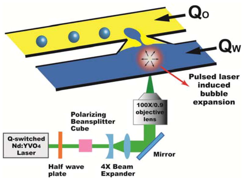
Schematic of the PLDG device that consists of two microfluidic channels connected by a nozzle-like opening. A highly focused intense laser pulse induces a rapidly expanding cavitation bubble to push nearby water into the oil channel for droplet formation.
The actuation mechanism of PLDG is based on laser pulse induced, rapidly expanding cavitation vapor bubbles. When an intense laser pulse is focused in a liquid medium such as water, the strong optical field induces water molecule breakdown which generates a hot plasma at the focal point.18–20 The heat quickly dissipates into the medium and creates a rapidly expanding cavitation bubble to perturb the stable oil-water interface and push the neighboring water into the oil channel to form aqueous droplets. The lifetime of a bubble from laser excitation to full collapse is bubble size dependent and varies from tens to hundreds microseconds in our experiments.
To induce cavitation bubbles, a Q-switched Nd:YVO4 pulsed laser beam (EKSPLA, Jazz 20) with a wavelength of 532 nm, 15 ns pulse width, and a maximum repetition rate of 100 kHz was focused through an objective lens (100x, NA 0.9) into the pulsed channel. This high-speed laser-induced droplet generation process was captured by a custom built time-resolved imaging system.21 A flashlamp (Nanolite, HIGH-SPEED PHOTO-SYSTEME) is used to provide illumination pulses with exposure times as short as 14 ns and was synchronized with a CCD camera (AxioCam MRm, ZEISS) and the laser. LabVIEW (NATIONAL INSTRUMENTS) programming enables our control of the number of laser pulses, the interval between pulses, and the delay time to trigger the flashlamp.
Fig. 2 presents captured time-resolved images that show the droplet formation process with PLDG. Corn oil for a continuous oil phase and a phosphate-buffered saline (PBS) buffer for a dispersed aqueous phase were used in all experiments. Before a laser pulse, the water and corn oil flow rates were adjusted to form a stable interface at the nozzle-shaped opening (Fig. 2(a)). Then, a bubble was excited within 1 μsec after the arrival of a laser pulse (Fig. 2(b)). The bubble size was maximum at 3 μsec and pushed water into the oil channel (Fig. 2(c)), with the bubble starting to collapse at 5 μsec (Fig. 2(d)). During the bubble collapse process, a neck-shaped connection was created between the droplet and the water channel (Fig. 2(e) ~ (f)). This connection was severed due to hydrodynamic instability (Fig. 2(g)). As a result, a 137-pL droplet was generated by a 100-μJ laser pulse in 500 μsec and transported away in the oil channel (Fig. 2(h) and (i)).
Fig. 2.

Time-resolved images of on-demand droplet generation using PLDG. A 137-pL droplet is generated by a 100-μJ laser pulse at Qw= 12 mL/h and Q0= 0.2 mL/h.
The volume of the injected droplets can be tuned either by adjusting the pulse laser energy or the laser excitation location. Fig. 3(a) ~ (d) shows the pulse energy-tuned droplet volume control. The pulsing location is fixed at 47 μm away from the left PDMS channel wall and the pulse energy is tuned by a beam polarizer from 100 μJ to 70 μJ. Since the pulse energy determines the bubble size, a higher energy pulse generates a larger water droplet. Fig. 3(e) ~ (f) shows the pulsing location-dependent droplet volume control with a fixed pulse energy of 100 μJ. Laser pulsing close to the oil-water interface produces small volume droplets. By controlling the pulse energy and pulsing location, we can tune the injected droplet volume from 1 pL to 150 pL.
Fig. 3.

Droplet size control by tuning the laser energy with (a) 100 μJ, (b) 90 μJ, (c) 80 μJ, and (d) 70 μJ at a pulsing location 47 μm away from the PDMS wall, and by varying the location of laser excitation at (e) 41 μm, (f) 62.5 μm, and (g) 75 μm away from the PDMS wall with a fixed 100-μJ pulsing energy.
A computer-controlled setup using LabVIEW 6.5 controls the number of laser pulses and the interval between each laser pulse. Fig. 4 shows continuous droplet generation with various laser pulsing intervals from 2 ms to 100 μs. On-demand droplet generation as fast as 10 000 droplets/sec has been achieved using PLDG (see Fig. 4(d)). One of the factors limiting the current droplet generation speed is the flow rate in the oil channel, which needs to be fast enough to remove a droplet before the next droplet is generated to prevent droplet merging at higher generation speeds. Higher droplet generation speeds are achievable with smaller droplets or higher oil flow speeds.
Fig. 4.

Continuous droplet generation with varied laser pulsing intervals, (a) 2 ms at Qw= 44 mL/h and Q0= 1.2 mL/h, (b) 1 ms at Qw= 60 mL/h and Q0= 2.4 mL/h, (c) 500 μs at Qw= 120 mL/h and Q0= 4 mL/h, and (d) 100 μs at Qw= 190 mL/h and Q0= 6.5 mL/h. In case (c), three laser pulses are used to demonstrate a droplet generation rate of 10 000 droplets/sec. The scale bar is 100 μm.
Droplet volume uniformity is very important in many lab-on-chip applications, especially for quantitative analyses. To evaluate droplet uniformity, droplets with colored dyes were produced under conditions used in Fig. 4(b) and (d), followed by collection in a dish (Fig. 5). The image processing toolbox in MATLAB 7.1 was used to analyze the collected droplet volume variation by taking cross sectional images. The injected droplets showed less than 1% volume variation.
Fig. 5.
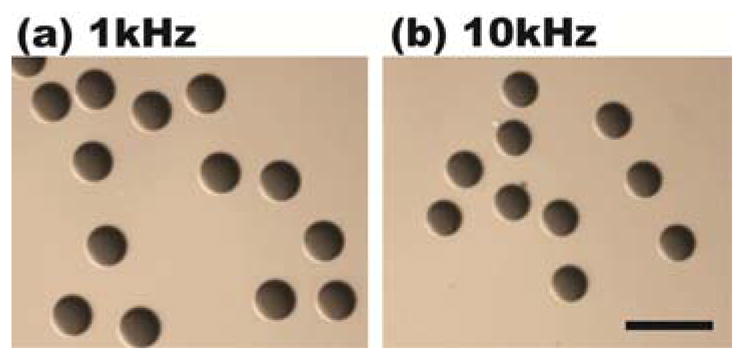
Droplets were continuously generated at (a) 1-kHz and (b) 10-kHz laser pulsing frequencies. Droplets were then collected in dishes for volume uniformity analysis. The scale bar is 100 μm.
Our microfluidic device reliability has been tested by continuously pulsing the water channel with 100-μJ pulses at a 1 kHz repetition rate for 1 hour, corresponding to 3.6 million bubble generation cycles. No damage was observed on the device.
To conclude, we present a pulse laser-driven droplet generation (PLDG) mechanism that enables high speed droplet generation on demand with precise and tunable volume control on a single-layer PDMS microfluidic device without any extra on-chip mechanical pumps or valves. On-demand droplet formation using PLDG is realized by a pulse laser-induced bubble expansion that perturbs a stable oil-water interface. We have experimentally demonstrated on-demand droplet generation at a speed of 10,000 droplets/sec. Droplets with a tunable volume between 1 pL and 150 pL have been generated either by adjusting the laser pulse energy or pulsing location. Droplet volume variations of less than 1 % have been estimated at both 1-kHz and 10-kHz repetition rates. Device reliability testing has shown no observable damage after continuous laser pulsing for 3.6 million bubble generation cycles. As such, PLDG provides a powerful approach for high-throughput and quantitative digital biochemical analyses.
Acknowledgments
This project is supported by a NSF CAREER Award (ECCS 0747950), NSF DBI-0852701, NSF ECCS 0901154, a UC Discovery Bioscience Biotechnology Award (#178517), the NIH Roadmap for Medical Research Nanomedicine Initiative (PN2EY018228), the Broad Center of Regenerative Medicine and Stem Cell Research at UCLA Innovation Award, and the Prostate Cancer Foundation Challenge Award.
Contributor Information
Sung-Yong Park, Email: pychiou@seas.ucla.edu.
Michael A. Teitell, Email: MTeitell@mednet.ucla.edu.
References
- 1.Brouzes E, Medkova M, Savenelli N, Marran D, Twardowski M, Hutchison JB, Rothberg JM, Link DR, Perrimon N, Samuels ML. Proc Natl Acad Sci USA. 2009;106:14195–14200. doi: 10.1073/pnas.0903542106. [DOI] [PMC free article] [PubMed] [Google Scholar]
- 2.Clausell-Tormos J, Lieber D, Baret JC, El-Harrak A, Miller OJ, Frenz L, Blouwolff J, Humphry KJ, Köster S, Duan H, Holtze C, Weitz DA, Griffiths AD, Merten CA. Chemistry & Biology. 2008;15:427–437. doi: 10.1016/j.chembiol.2008.04.004. [DOI] [PubMed] [Google Scholar]
- 3.Huebner A, Srisa-Art M, Holt D, Abell C, Hollfelder F, deMello AJ, Edel JB. Lab Chip. 2007:1218–1220. doi: 10.1039/b618570c. [DOI] [PubMed] [Google Scholar]
- 4.Roach LS, Song H, Ismagilov RF. Anal Chem. 2005;77:785–796. doi: 10.1021/ac049061w. [DOI] [PMC free article] [PubMed] [Google Scholar]
- 5.Li W, Pham HH, Nie Z, MacDonald B, Genther A, Kumacheva E. J Am Chem Soc. 2008;130:9935–9941. doi: 10.1021/ja8029174. [DOI] [PubMed] [Google Scholar]
- 6.Chang YH, Lee GB, Huang FC, Chen YY, Lin JL. Biomed Microdevices. 2006;8:215–225. doi: 10.1007/s10544-006-8171-y. [DOI] [PubMed] [Google Scholar]
- 7.Lau BTC, Baitz CA, Dong XP, Hansen CL. J Am Chem Soc. 2007;129:454. doi: 10.1021/ja065855b. [DOI] [PubMed] [Google Scholar]
- 8.Hung LH, Choi KM, Tseng WY, Tan YC, Shea KJ, Lee AP. Lab Chip. 2006;6:174–178. doi: 10.1039/b513908b. [DOI] [PubMed] [Google Scholar]
- 9.Hatakeyama T, Chen DL, Ismagilov RF. J Am Chem Soc. 2006;128:2518–2519. doi: 10.1021/ja057720w. [DOI] [PMC free article] [PubMed] [Google Scholar]
- 10.Edd JF, Carlo DD, Humphry KJ, Köster S, Irimia D, Weitz DA, Toner M. Lab Chip. 2008;8:1262–1264. doi: 10.1039/b805456h. [DOI] [PMC free article] [PubMed] [Google Scholar]
- 11.Joanicot M, Ajdari A. Science. 2005:309. doi: 10.1126/science.1112615. [DOI] [PubMed] [Google Scholar]
- 12.Yobas L, Martens S, Ong WL, Ranganathan N. Lab Chip. 2006;6:1073–1079. doi: 10.1039/b602240e. [DOI] [PubMed] [Google Scholar]
- 13.Gong J, Kim CJ. Lab Chip. 2008;8:898–906. doi: 10.1039/b717417a. [DOI] [PMC free article] [PubMed] [Google Scholar]
- 14.Xu J, Attinger D. J Micromech Microeng. 2008;18:065020. [Google Scholar]
- 15.Zeng S, Li B, Su X, Qin J, Lin B. Lab Chip. 2009;9:1340–1343. doi: 10.1039/b821803j. [DOI] [PubMed] [Google Scholar]
- 16.Hsiung SK, Chen CT, Lee GB. J Micromech Microeng. 2006;16:2403–2410. [Google Scholar]
- 17.McDonald JC, Duffy DC, Anderson JR, Chiu DT, Wu H, Schueller OJA, Whitesides GM. Electrophoresis. 2000;21:27–40. doi: 10.1002/(SICI)1522-2683(20000101)21:1<27::AID-ELPS27>3.0.CO;2-C. [DOI] [PubMed] [Google Scholar]
- 18.Dijkink R, Ohla CD. Lab Chip. 2008;8:1676–1681. doi: 10.1039/b806912c. [DOI] [PubMed] [Google Scholar]
- 19.Vogel A, Busch S, Parlitz U. J Acoust Soc Am. 1996;100:148–165. [Google Scholar]
- 20.Chang RK, Eickmans JH, Hsieh W-F, Wood CF, Zhang J-Z, Zheng J-b. Appl Opt. 1988;27:2377–2385. doi: 10.1364/AO.27.002377. [DOI] [PubMed] [Google Scholar]
- 21.Wu TH, Gao L, Chen Y, Wei K, Chiou PY. Appl Phys Lett. 2008;93:144102. [Google Scholar]