Abstract
Inductive coupling is a viable scheme to wirelessly energize devices with a wide range of power requirements from nanowatts in radio frequency identification tags to milliwatts in implantable microelectronic devices, watts in mobile electronics, and kilowatts in electric cars. Several analytical methods for estimating the power transfer efficiency (PTE) across inductive power transmission links have been devised based on circuit and electromagnetic theories by electrical engineers and physicists, respectively. However, a direct side-by-side comparison between these two approaches is lacking. Here, we have analyzed the PTE of a pair of capacitively loaded inductors via reflected load theory (RLT) and compared it with a method known as coupled-mode theory (CMT). We have also derived PTE equations for multiple capacitively loaded inductors based on both RLT and CMT. We have proven that both methods basically result in the same set of equations in steady state and either method can be applied for short- or midrange coupling conditions. We have verified the accuracy of both methods through measurements, and also analyzed the transient response of a pair of capacitively loaded inductors. Our analysis shows that the CMT is only applicable to coils with high quality factor (Q) and large coupling distance. It simplifies the analysis by reducing the order of the differential equations by half compared to the circuit theory.
Index Terms: Coupled-mode theory (CMT), near field, quality factor, power transfer efficiency (PTE), reflected load theory, resonance circuits, wireless power transmission
I. Introduction
Inductive power transmission links that utilize a pair of mutually coupled coils have been in use over the last decades to power up radio frequency identification (RFID) transponders and cochlear implants with power consumptions in the range of sub-micro to milliwatts [1], [2]. The use of this technique to wirelessly transfer energy across a short distance is, however, expected to see an explosive growth over the next decade in a much broader range of applications from advanced implantable microelectronic devices (IMD), such as retinal implants and brain–computer interfaces (BCI) to cut the power cord in charging mobile electronic devices, operating small home appliances, and energizing electric cars, which have higher power consumptions in the order of hundreds of milliwatts to kilowatts [3]–[12]. As a result, improving the wireless power transmission efficiency (PTE) in inductive links particularly at larger coupling distances (coil separations) without increasing the volume and weight of the coupled coils has gained considerable attention [13]–[19].
Achieving high PTE is necessary in high-power IMDs to not only reduce the size of the external energy source (battery) that should be carried around by the patient but also to limit the tissue exposure to the AC magnetic field, which can result in excessive heat dissipation if it surpasses safe limits, and to minimize interference with near by electronics [20]–[22]. In near field RFID applications, the bottleneck in increasing the reading range without changing the coil size in many cases is the PTE when the received power is no longer sufficient to operate the transponder [2]. Increasing the PTE in higher power applications is also important for generating less heat, cost saving, reducing interference, and improving safety.
Design and optimization of inductive power transmission links has been extensively studied in the literature over the last three decades [2], [5], [23]–[34]. The majority of these approaches model and analyze the inductive link from a circuit perspective, which differs, at least on the surface, from the coupled-mode theory (CMT) that was recently presented in a new form by physicists at MIT [35]. They utilized the CMT approach to propose multi-coil inductive links, which can increase the PTE considerably at large coupling distances [13], [14]. Their 4-coil inductive link has so far been studied from a circuit perspective for power transmission to multiple small receivers, transcutaneous powering, and recharging mobile devices [17]–[19]. We have presented the analysis, modeling, design, and optimization of multi-coil inductive links using the circuit based reflected load theory (RLT) in [36]. However, an in-depth comparison between the coupled-mode and circuit-based theories, which would clarify the relationship between these two methods, often used by physicist and electrical engineers, respectively, is still lacking.
In this paper, first we review the inductive link steady-state analysis using CMT and then prove that both CMT and the more conventional RLT result in the same formulation for the inductive links' key performance measures, particularly the PTE. For the first time, we have derived the PTE equations for multi-coil inductive links via CMT. Our analysis shows that in the steady state mode, contrary to popular belief, both CMT and RLT are applicable to small and large coupling distances, d, as long as the coils interact in the near field regime. Because they are basically the same [37]! We have also presented the measurement results, which show the accuracy of both RLT and CMT models in estimating the PTE. On the other hand, our comparative transient analysis of a pair of capacitively loaded inductors reveals that CMT is accurate only if the mutual coupling, k, is small, e.g., due to large d, and coil quality factors, Q, are large, which limits the applicability of the CMT-based transient analysis to midrange coupling distances of large coils. We have also shown that utilizing CMT reduces the order of the differential equations by half compared to the circuit theory as it only considers a first order equation for each resonant object. Hence, the CMT seems to be helpful in analyzing the transient behavior of complicated multi-coil inductive links despite being less accurate than its circuit-based counterpart. For all other conditions, the RLT and similar circuit based methods will do just fine.
In the following section, the CMT analysis for a pair of capacitively loaded inductors is presented. Section III describes the RLT analysis for 2-coil inductive links. The correspondence between CMT and RLT has been presented in Section IV. The PTE analysis of the multi-coil inductive links utilizing both CMT and RLT are presented in Section V. The calculation and measurement results are compared in Section VI followed by concluding remarks in Section VII.
II. Coupled-Mode Theory
CMT is a framework to analyze energy exchange between two resonating objects [35]. Based on the CMT, the time-do-main field amplitudes of two objects, a2(t) and a3(t), which are defined so that the energy contained in them are and |a2(t)|2 and |a3(t)|2, respectively, at distance d23 can be found from [37]
| (1) |
Where ω2 and ω3 are the eigen frequencies, Γ2 and Γ3 are the resonance widths or rate of intrinsic decay due to the objects' absorption (Ohmic) and radiative losses, ΓL is the resonance width due to load resistance connected to the second object (proportional to 1/RL), FS(t) is the excitation applied to the first object, and K23 is the coupling rate between the two objects. The CMT method has been recently applied to a pair of capacitively loaded conducting-wire loops, spaced by d23, as shown in Fig. 1, forming a conventional inductive power transmission link, in which L2 is the power transmitter and L3 is the power receiver inductors, both tuned at the same frequency, ω2 = ω3 = ω [14], [37].
Fig. 1.
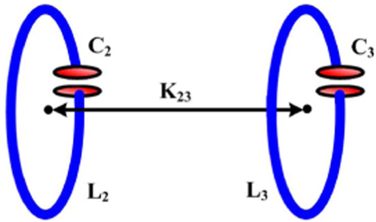
A pair of capacitively loaded inductors used for efficiency calculation using the coupled-mode theory (CMT).
A. Steady-State Analysis via Coupled-Mode Theory
In steady state analysis, which applies to the conventional inductive power transmission links, FS(t) in (1) is a sinusoidal signal described as Ase−jωt. In this condition, the alternating field amplitude in the primary inductor is constant, a2(t) = A2e−jωt, resulting in a constant field amplitude in the secondary inductor, a3(t) = A3e−jωt. It can be shown from (1) that A3/A2 = jK23/(Γ3+ΓL) [37]. Therefore, the average power at different nodes of the power transmission system can be calculated. The power absorbed by L2 and the power delivered to L3 are P2 = 2Γ2|A2|2 and P3 = 2Γ3|A3|2, respectively. The power delivered to RL is PL = 2ΓL|A3|2 and, therefore, based on the energy conservation theory, if we neglect the radiated power in the near field regime, the total power delivered to the system from source is PS = P2 + P3 + PL. Hence, the PTE of the 2-coil system can be found from
| (2) |
where is the distance-dependent figure-of-merit for energy transmission systems [37]. To maximize the PTE based on (2), fom should be maximized and an optimal value should be chosen for ΓL/Γ3. Parameters that affect fom are obviously the coupling rate between the two objects, K23, which should be increased and the resonance width of each object (intrinsic loss of each inductor), Γ, which should be decreased. These are quite similar to the coupling coefficient, k23, and inverse of the quality factor, 1/Q, used in conventional methods for optimizing inductive links [33]. The other key parameter, ΓL,PTE/Γ3, which shows the effect of RL in optimizing the PTE, can be found by calculating the derivative of η23 in (2) with respect to ΓL/Γ3, resulting in [13]
| (3) |
B. Transient Analysis via Coupled-Mode Theory
The CMT can also be utilized in analyzing the transient behavior of the resonant-coupled inductors in Fig. 1 by setting FS(t) = 0 in (1) and considering an initial energy stored in L2. This analysis provides designers with better understanding of the dynamics of energy exchange in such inductively coupled systems. As the first step, we eliminate a3(t) in (1) to find an expression for the time varying field in the primary coil
| (4) |
For the sake of simplicity, if similar to [14] we assume that the two inductors are identical, i.e., Γ2 = Γ3 = Γ, and ΓL = 0 (no load condition, RL = ∞), then a2(t) can be found from (4):
| (5) |
Where b1 and b2 are constants, which values depend on the initial conditions. Similarly, a3(t) can be calculated using (1) and (5) as
| (6) |
Where d1 and d2 are also constants with values dependent on the initial conditions. The total energy in L2 and L3 can be found from E2(t) = |a2(t)|2 and E3(t) = |a3(t)|2, respectively [24].
If one starts with 100% of the total energy normalized and initially stored in L2, i.e., |a2(t = 0)|2 = 1 and |a2(t = 0)|2 = 0, the energy stored in each object over time can be found from
| (7) |
It should be noted that E2 and E2 are not the instantaneous but the peak values (or envelopes) of the energy content stored in L2 and L3, which are in resonance with C2 and C3, respectively, at the rate of 2ω.
III. Reflected Load Theory
Fig. 2(a) shows a pair of inductively coupled coils, which will be referred to as the primary (L2) and secondary (L3). It can be shown that the highest PTE across such link scan be achieved when both LC-tanks are tuned at the same resonance frequency, i.e., [31].
Fig. 2.
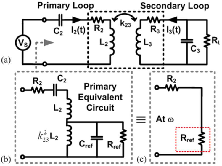
(a) Simplified model of a 2-coil power transmission link with a resistive load. (b) Equivalent circuit seen across the driver. (c) Reflected load onto the primary loop at resonance frequency.
A. Steady State Analysis via Reflected Load Theory
The inductive link PTE is mainly dependent on the mutual coupling between the coils, k23, and their quality factors, Q2 = ωL2/R2 and Q3 = ωL3/R3 [33]. At resonance frequency, the secondary loop which is connected to RL can be reflected on to the primary loop and represented by Rref [2]. To find Rref, the secondary loop is modeled with a parallel load as shown in Fig. 2(a). R3, the parasitic resistance of L3, can be transformed to a parallel resistance equal to in parallel with RL [30]. Hence, if we define, RP = RP3 ║ RL then we can reflect the secondary impedance onto the primary side [Fig. 2(b)]:
| (8) |
Where Q3L = RP/ωL3 is the loaded quality factor of the secondary coil [9], [30]. At resonance, Cref resonates out with, , leaving only the reflected resistance, Rref, on the primary side, as shown in Fig. 2(c). In the simplified inductive link model of Fig. 2(c), L2 and L3 also resonate out, and the input power provided by Vs simply divides between R2 and Rref. The power absorbed by R2 is dissipated as heat in the primary coil and the power delivered to Rref, i.e., the transferred power to the secondary loop, divides between R3 and RL, which are the only power consuming components on the secondary side. This will lead to
| (9) |
Where QL = RL/ωL3 is often referred to as the load quality factor, and Q3L = Q3QL/(Q3+QL) [31]. It can be seen from (9) that large k23, Q2 and Q3 are needed to maximize the PTE. However, for a given set of Q2, Q3 and k23 values, there is an optimal load, RL,PTE = ωL3QL,PTE, which can maximize the PTE. QL,PTE can be found by calculating the derivative of (9) with respect to QL from
| (10) |
B. Transient Analysis via Circuit Theory
In this analysis, the primary and secondary loops are considered identical, i.e., L2 = L3 = L, C2 = C3 = C, R2 = R3 = R and RL = ∞, similar to the CMT criteria in [14]. We have also set Vs = 0 V (short circuit) to focus on the transient response while considering an initial condition (current) in L2. Primary and secondary loop currents can be found from
| (11) |
Where M = k23 × L is the mutual inductance between L2 and L3. Taking the derivative of (11) after substituting R/L and 1/LC with ω/Q and ω2, respectively, result in
| (12) |
Utilizing Laplace transform, (12) can be written as
| (13) |
Characteristic equation in the S-domain can be found by setting the coefficient matrix determinant in (13) to zero:
| (14) |
The roots of (14) are
| (15) |
where
| (16) |
Therefore, I2(t) and I3(t) can be calculated from
| (17) |
| (18) |
In order to find the unknown coefficients in (17) and (18), one should have at least four initial conditions. Two of them are I2(0) = I0, and I3(0) = 0 A, which indicate that 100% of the total energy is initially stored in L2. The other two initial conditions can be found from (11) when t = 0:
| (19) |
IV. Coupled Mode Versus Reflected Load Theories
In this section, we compare the formulation derived from CMT and RLT for the 2-coil inductive link PTE and transient response derived in the previous sections.
A. Two-Coil Inductive Link Power Transfer Efficiency
Resonance widths, Γ2,3, and coupling rate, K23, in a pair of capacitively loaded inductors in Fig. 1 are equivalent in terms of circuit model parameters in Fig. 2 to ω/2Q2−3 and ωk23/2, respectively [37]. Similarly, the load resonance width, ΓL, is equal to ω/2QL. By substituting these in fom and ΓL/Γ3
| (20) |
In the next step, we substitute the CMT parameters from (20) in (2) and recalculate the PTE
| (21) |
After simplification and considering that Q3L = QLQ3/(QL + Q3), the PTE formula in (21) can be further simplified to
| (22) |
which is the same as (9) that was derived via RLT.
Similarly, it is straightforward to show that the optimum ΓL, PTE in (3) can be linked to QL, PTE in (10) by substituting the equivalent circuit parameters in (20), leading to
| (23) |
Thus, we have shown mathematically that the CMT and RLT equations for the PTE and optimal loading of 2-coil power transmission links in steady state are basically the same.
B. Two-Coil Inductive Link Transient Response
In order to arrive at the CMT transient response in (7), two assumptions were made. First, the coil quality factors were considered large (Q ≫ 1), resulting in and in (16). Second, the coupling distance, d23, was considered large, resulting in small k23, which simplifies the rest of (16) to
| (24) |
and (19) to
| (25) |
Thus, I2(t) and I3(t) in (17) and (18) can be approximated as
| (26) |
| (27) |
Unknown coefficients in (26) and (27) can be found by applying the initial conditions, which result in a11 = a12 = I0/2, b11 = b12 = −I0/4Q, a21 = −a22 = −I0/2, and b21 = b22 = 0. When substituting these in (26) and (27)
| (28) |
| (29) |
The large Q assumption combined with the expansion of the sinusoidal functions in (28) and (29)
| (30) |
can further simplify the primary and secondary currents as
| (31) |
Considering that the energy stored in an inductor, L, that carries a current, I, is 0.5LI2, the normalized envelope of the energy inside L2 and L3 can be expressed as [38]
| (32) |
By substituting 2Γ = ω/Q, and K23 = ωk23/2 in (32), we can arrive at (7), which was derived using CMT. Therefore, in calculating the transient response of the inductive links, CMT is only valid for midrange coupling distances (small k23) between large coils (high-Q), as also indicated in [37].
In order to validate our theoretical calculations and demonstrate the level of accuracy (or lack there of) in the transient CMT analysis for various coupling coefficients and Q factors, the 2-coil inductive link in Fig. 2 was simulated in the LT-SPICE circuit simulator (Linear Technology, Milpitas, CA), while setting VS and initial L2 current, I2(0), at 0 V and 1 A, respectively, for the two conditions summarized in Table I. Fig. 3(a) shows the percentage of the energy stored in primary, L2, and secondary, L3, coils over time for a pair of large identical coils that are placed relatively far from each other (midrange, low k23, high-Q). It can be seen that both CMT (7) and circuit-based (12) equations, solved in MATLAB (MathWorks, Natick, MA), match the LT-SPICE simulation results very well. In Fig. 3(b), however, which represents a small pair of coils that are very close to one another (short range, high k23, low-Q) the CMT-based formulas have become quite inaccurate in predicting the energy exchange, while the circuit analysis still matches the LT-SPICE simulation output. In this condition, the inductor currents tend to have two harmonics, ω′ and ω″ in (17) and (18), one of which has not been predicted by the CMT. Nonetheless, the simplicity of the CMT in analyzing the transient behavior of inductive links can be useful particularly in midrange high-Q conditions. This stems from the fact that CMT models each resonant object (e.g., RLC tank) with a first-order differential equation, while in the circuit analysis the order of the equations increases by each independent energy storage element regardless of being an inductor or a capacitor.
Table I. Inductive Link Specifications for Transient Analyses.
| L2 and L3 Specifications* | Symbol | Midrange High-Q | Short Range Moderate-Q |
|---|---|---|---|
| Inductance (μH) | L | 96.2 | 0.962 |
| Series resistance (Ω) | R | 0.76 | 1.08 |
| Resonant capacitance (pF) | C | 0.812 | 81.2 |
| Quality factor | Q | 1.4×10⁴ | 100 |
| Mutual coupling | k23 | 0.153×10⁻³ | 0.4 |
| Resonance width (rad) | Γ | 4039 | 5.65×10⁵ |
| Coupling rate (rad) | K23 | 8652 | 22.6 ×10⁶ |
| Load resistance (Ω) | RL | ∞ (No load condition) | |
| Resonance frequency (MHz) | f | 18 | |
Primary and secondary coils are identical.
Fig. 3.
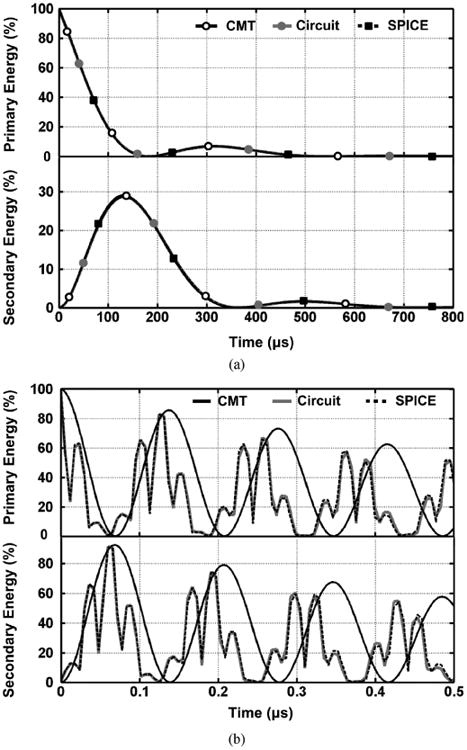
Energy stored in the primary and secondary coils (E2 and E3) versus time starting from an initial condition, I2(0) = 1 A, based on CMT (7), circuit theory (12), and SPICE simulations for 2-coil inductive links in: (a) midrange, high-Q, and (b) short range, low-Q conditions, as specified in Table I.
V. Multi-Coil Inductive Power Transfer
CMT-based analysis took circuit designers by surprise when the group physicists at MIT demonstrated a method of achieving high PTE by utilizing multiple coils (3- and 4-coils) for wireless power transmission [13], [14]. Nonetheless, the closed-form CMT formulation presented in the literature was limited to 2-coils. In this section, we derive the closed-form PTE equations for multi-coil inductive links based on the CMT and compare them with parallel equations derived from RLT, particularly for 3- and 4-coil links [36]. We prove that both CMT and RLT result in the same set of equations.
Equations for a pair of capacitively loaded inductors in Fig. 1 can be extended to m inductors, in which the first and mth inductors are connected to the energy source and load, respectively, while all inductors are tuned at the same resonance frequency, f [14]. The time-domain field amplitudes of each inductor, ai(t), can be expressed as
| (33) |
where Ki,i+1 and Γi are the coupling rate between the ith and (i + 1)th inductor and resonance width of the ith inductor, respectively. For the sake of simplicity, the coupling between non-neighboring inductors has been considered negligible. For the first and mth inductors, the field amplitudes are
| (34) |
In the steady state mode, the field amplitudes in each inductor is considered constant, i.e., ai(t) = Aie−jωt. Therefore, the differential equations in (33) and (34) result in a set of m − 1 equations
| (35) |
One can solve (35) to find Ai constants based on the load field amplitude, Am. From these values, the average power at different nodes of the inductive power transmission link can be calculated. The absorbed power by the ith inductor and the delivered power to RL can be expressed as Pi = 2Γi|Ai|2 and PL = 2ΓL|Am|2, respectively, from which the total delivered power to the system from source can be found from , using the law of conservation of energy. Finally, the PTE of the m-coil system can be found from
| (36) |
In an m-coil link, the reflected load from the (i + 1)th coil onto the ith coil can be found from
| (37) |
where ki,i+1 is the coupling coefficient between the ith and (i + 1)th coils. Q(i+1)L is the loaded quality factor of the (i + 1)th coil, which can be found from
| (38) |
where Qi = ωLi/Ri and Ri are the unloaded quality factor and parasitic series resistance of the ith coil (Li), respectively. It should be noted that for the last coil, which is connected to the load in series, QmL = ωLm/(Rm + RL). Assuming that the coupling between non-neighboring coils is negligible, the partial PTE from the ith coil to (i + 1)th coil can be written as
| (39) |
Using (37)–(39), the overall PTE in such a multi-coil inductive link can be found from
| (40) |
A. Three-Coil Power Transfer Inductive Links
The 3-coil inductive power transfer link, shown in Fig. 4(a), was initially proposed in [14] and analyzed based on the CMT. If we ignore K24 due to large separation between L2 and L4, the field amplitudes at each inductor can be calculated by solving a set of two equations in (35), which leads to
Fig. 4.
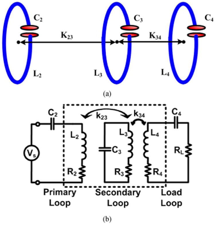
(a) Three capacitively loaded, mutually coupled, inductors for wireless power transmission in which L4and K34 serve as impedance matching elements to improve the PTE. (b) Lumped circuit model of the 3-coil inductive link.
| (41) |
PTE of the 3-coil link can then be found by substituting (41) in (36), which leads to (42) after some minor simplifications, as shown at the bottom of the page.
| (42) |
The lumped circuit model for 3-coil inductive link has been shown in Fig. 4(b). In this type of inductive links, k34 can be adjusted by changing the distance or geometry of L4 to match the actual RL with the optimal RL,PTE in (10) for the L2–L3 inductive link. It should be noted that R2, which is the series resistance of L2, can also include the source output resistance [36]. The PTE of this circuit can be calculated by reflecting the resistive components of each loop from the load back towards the primary coil loop, one stage at a time, using (37) and calculating the percentage of the power that is delivered from one stage to the next, using (39), until it reaches RL. According to (40), this procedure leads to
| (43) |
where k24 has been ignored due to large separation between L2 and L4, and
| (44) |
The resonance widths, Γ2–4, and coupling rates, K23,34, in CMT based on circuit parameters are defined as ω/2Q2–4 and ωk23,34/2, respectively [37]. By substituting these parameters in (42) and multiplying both numerator and denominator with , the 3-coil PTE can be found from
| (45) |
where 1/Q4L = 1/Q4 + 1/QL. It can be seen that (45), which is derived from the CMT is the same as (43), which is based on the RLT. Therefore, these two formulations are not different in the steady state analysis.
B. Four-Coil Power Transfer Inductive Links
Fig. 5(a) shows an inductive power transfer link consisting of four capacitively loaded inductors, in which L2 and L3 are the main coils responsible for power transmission, similar to the 2-coil link, while L1 and L4 are added for impedance matching [18], [36], [37]. The field amplitudes at each inductor can be found by solving a set of three equations in (35). A2 and A3 can be found based on A4 from (41) and A1 can be found from
Fig. 5.
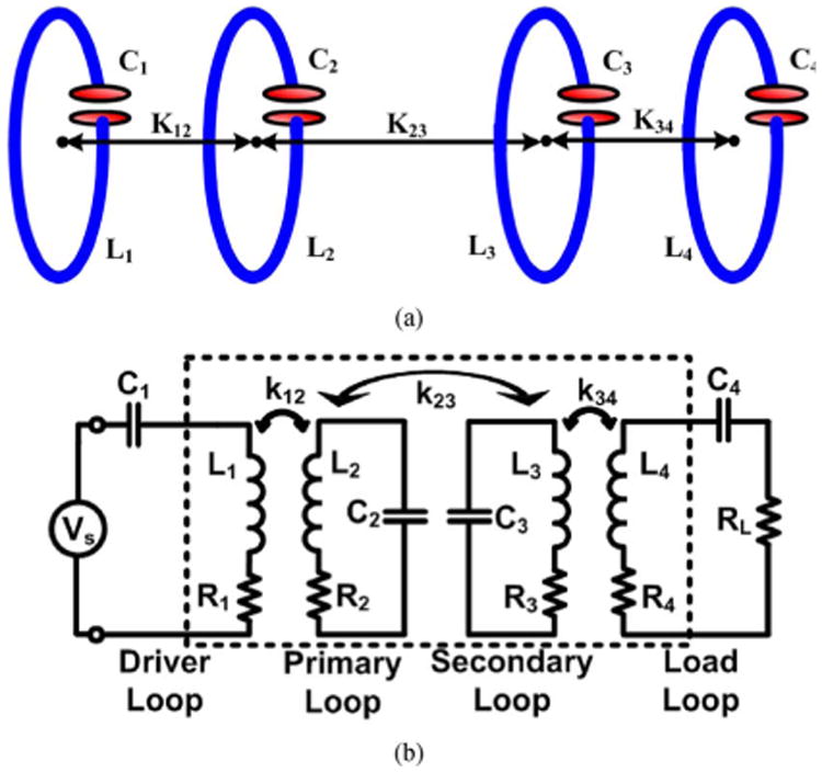
(a) Four capacitively loaded, mutually coupled, inductors for wireless power transmission, in which L1 – K12 and L4 – K34 serve as impedance matching elements to improve the PTE. (b) Lumped circuit model of the 4-coil inductive link.
| (46) |
To simplify the analysis, K13, K14 and K24 have been neglected in comparison to coupling rates between neighboring coils. One can find the 4-coil PTE utilizing CMT by substituting (41) and (46) in (36), which after simplification leads to
| (47) |
where
| (48) |
In the 4-coil lumped circuit schematic, shown in Fig. 5(b), the PTE can be calculated from (40) if we ignore k13, k14, and k24 in comparison to k12, k23 and k34 [18], shown in (49) at the bottom of the page.
| (49) |
We can prove that CMT and RLT equations in (47) and (49) are basically the same by substituting the resonance widths, Γ1–4, and coupling rates, K12, K23, and K34 in (47) and (48) with their equivalent circuit parameters, ω/2Q1–4, ωk12/2, ωk23/2, and ωk34/2, respectively [37]. Once both numerator and denominator of (47) are multiplied by , the CMT-based 4-coil PTE leads to (50), shown at the bottom of the next page, where A and B are
| (50) |
| (51) |
The third and fourth terms of the denominator in (50) can be written in terms of B as
| (52) |
By further manipulation of the numerator and denominator
| (53) |
Once A and B are substituted from (51) in (53), it will be identical to (49), which was derived from the RLT.
VI. Modeling Versus Measurement Results
In order to verify the accuracy of the PTE equations derived from the RLT and CMT in measurements, we designed and fabricated three sets of inductive links with 2, 3, and 4 coils. L2 and L3 in all three links were identical printed spiral coils (PSCs), fabricated on 1.5-mm-thick FR4 printed circuit boards (PCB) with 1-oz copper (35.6 μm thick). L4 and L1 in the 3- and 4-coil links were made of single filament solid copper wires, placed in the middle of L3 and L2, respectively [see Fig. 6(b)]. Given and L3 geometries, the identical diameter of L4 and L1 were optimized based on the procedure that we presented in [36] for the nominal coupling distance of d23 = 30 cm, RL = 100 Ω, and f0 = 13.56 MHz. Table II shows specifications these three inductive links.
Fig. 6.
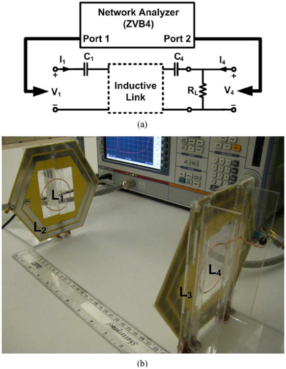
(a) PTE measurement setup using a network analyzer with all the coils tuned at the carrier frequency and RL connected to the load coil. (b) Four-coil inductive link used to measure the PTE (specifications in Table II).
Table II. Inductive Link Specifications for Power Transfer Efficiency Measurements.
| Parameters | Symbols | 2-Coil | 3-Coil | 4-Coil | ||
|---|---|---|---|---|---|---|
| L1 / L4 | Inductance (μH) | L1 / L4 | - | 0.57 | 0.57 | |
| Outer diameter (cm) | Do1 / Do4 | - | 5.2 | 5.2 | ||
| Fill factor | Φ1 / Φ4 | - | 0.027 | 0.027 | ||
| Num. of turns | n1 / n4 | - | 2 | 2 | ||
| Line width (mm) | w1 / w4 | - | 0.64 | 0.64 | ||
| Line spacing (μm) | s1 / s4 | - | 100 | 100 | ||
| Quality factor | Q1 / Q4 | - | 183 | 183 | ||
| Resonance width (rad) | Γ1 / Γ4 | - | 2.3×10⁵ | 2.3×10⁵ | ||
| L2 / L3 | Inductance (μH) | L2 / L3 | 0.9 | |||
| Outer diameter (cm) | Do2 / Do3 | 16.8 | ||||
| Fill factor | Φ2 / Φ3 | 0.13 | ||||
| Num. of turns | n2 / n3 | 2 | ||||
| Line width (mm) | w2 / w3 | 8.66 | ||||
| Line spacing (mm) | s2 / s3 | 2.6 | ||||
| Quality factor | Q2 / Q3 | 255 | ||||
| Resonance width (rad) | Γ2 / Γ3 | 1.67×10⁵ | ||||
| L2 and L3 coupling distance (cm) | d23 | 30 | ||||
| L2-L3 mutual coupling | k23 | 6.6×10⁻³ | ||||
| L2-L3 coupling rate (rad) | K23 | 2.8×10⁵ | ||||
| L1-L2 / L3-L4 mutual coupling | k12 / k34 | - | 0.09 | 0.09 | ||
| L1-L2 / L3-L4 coupling rate (rad) | K12 / K34 | - | 3.8×10⁶ | 3.8×10⁶ | ||
| Power transfer efficiency (%) | Calculated | η | 1.1 | 31.4 | 31.3 | |
| Measured | 1.37 | 29.7 | 27.9 | |||
| Nominal load (Ω) | RL | 100 | ||||
| Power carrier frequency (MHz) | f0 | 13.56 | ||||
L1 and L4 are WWCs, while L2 and L3 are hexagonal PSCs.
Fig. 6(a) shows the measurement setup that we used for the PTE, which is quite suitable for multi-coil inductive links [36]. In this method, resonance capacitors and RL are added to the driver and load coils, and the entire circuit is considered a 2-port system including the multi-coil inductive link in between. A network analyzer is used to measure the S-parameters, from which the Z-parameters are derived [39]. The PTE can then be found from 2-port equations
| (54) |
where Z11 = V1/I1 and Z41 = V4/I1 are derived when I4 = 0. The I4 = 0 requirement in calculating the Z-parameters ensures that the network analyzer loading (often 50 Ω) on the inductive link does not affect the measurement results. Fig. 6(b) shows the 4-coil inductive link, which coils were held in parallel and perfectly aligned using sheets of Plexiglas. L4 and L1 and were placed in the middle of L3 and L2 and in a coplanar fashion, respectively, to achieve k12 = k34 = 0.09.
Fig. 7 compares the measured versus calculated values of the PTE versus coupling distance in the 2-, 3-, and 4-coil inductive links. Calculated PTE values are from the RLT and CMT models described in previous sections, while the circuit parameters, such as k and Q, are extracted from the models presented in [33] and [36] for PSCs and wire-wound coils, respectively. It can be seen that both RLT and CMT models, which are basically the same in steady state, estimate the PTE with a high level of accuracy.
Fig. 7.
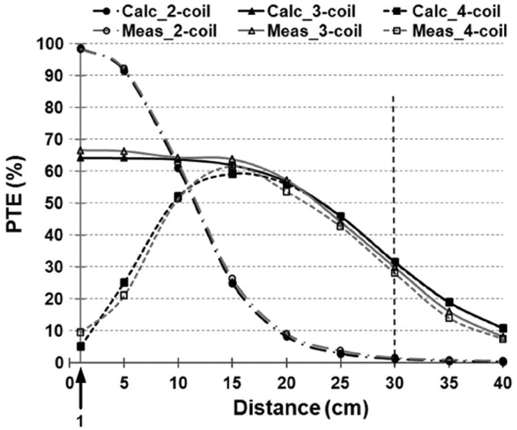
Comparison between measured and calculated (using RLT or CMT equations) values of the PTE versus the coupling distance, d23, for 2-, 3-, and 4-coil inductive links specified in the Table II.
It can be seen from Table II that the calculated PTEs of the 3- and 4-coil links at d23 = 30 cm are 31.4% and 31.3%, which are very close to the measured results, 29.7% and 27.9%, respectively. On the other hand, the measured 2-coil PTE at the same distance (1.37%) shows a greater difference on a percentage basis from the calculated value of 1.1%. This is most likely due to the measurement errors and equipment non-idealities at very low PTE levels. Because, as shown in Fig. 7, the calculated and measured PTEs for the same 2-coil link match very well at higher PTE values. The measured and calculated PTEs in 3- and 4-coil links show slightly more differences at smaller d23 < 5 cm. This is because for the sake of simplicity, we have neglected non-neighboring coils' coupling in our models in Section V, which are more significant when d23 is small. We would also like to point out that the 2-coil PTE at d23 = 30 cm is ∼21 times smaller than that of 3- and 4-coil links because L3 cannot provide QL values close to the QL,PTE in (10) for RL = 100 Ω in the 2-coil link. On the other hand, the 3- and 4-coil links can achieve the optimal QL,PTE owing to their extra degree of freedom in impedance transformation, provided by k34, which determines the optimal sizing of L4 and L1 [36].
VII. Conclusion
Electrical engineers analyze inductively coupled coils, transformers, and RLC tank circuits using lumped models, well known Kirchhoff's current/voltage laws, and a method often referred to as the RLT. Physicists, on the other hand, prefer to consider the energy stored in the system and exchanged between two or more resonating objects (in this case capacitively loaded conductive-wire loops) and use a method known as the CMT. We have presented detailed formulation for calculating the PTE based on both theories for a conventional 2-coil inductive power transmission link, and extended the solutions in the steady state to 3-, 4-, and m-coil systems. In each case, we have proven that despite using different parameters and terminologies, both CMT and RLT lead to the exact same set of equations, and therefore, both are applicable to short- and midrange coil arrangements as long as near-field non-radiative conditions are applicable to the resonating circuits. Moreover, we have derived equations describing the transient behavior of the 2-coil inductive power transmission links using both the CMT and circuit theory. Theoretical analysis and simulation results show that in this case, CMT is only accurate when coils have small coupling and large quality factors. However, it simplifies the analysis by reducing the order of the differential equations by half, compared to the circuit-based approach. The measurement results show that the RLT and CMT equations are both sufficiently accurate for the PTE calculation.
Acknowledgments
The authors would like to thank members of the GT-Bionics lab for their comments and constructive discussions.
This work was supported in part by the National Institutes of Health, NIBIB, under Grant 1R21EB009437-01A1, and in part by the National Science Foundation under Award ECCS-824199.
Biographies

Mehdi Kiani (S'09) received the B.S. degree from Shiraz University, Shiraz, Iran, in 2005 and the M.S. degree from Sharif University of Technology, Tehran, Iran in 2008. He is currently pursuing the Ph.D. degree in the GT-Bionics Lab at the Georgia Institute of Technology, Atlanta.

Maysam Ghovanloo (S'00-M'04-SM'10) was born in Tehran, Iran, in 1973. He received the B.S. degree in electrical engineering from the University of Tehran, Tehran, in 1994, the M.S. degree in biomedical engineering from the Amirkabir University of Technology, Tehran, in 1997, and the M.S. and Ph.D. degrees in electrical engineering from the University of Michigan, Ann Arbor, in 2003 and 2004, respectively.
From 2004 to 2007, he was an Assistant Professor in the Department of Electrical and Computer Engineering, North Carolina State University, Raleigh. In June 2007, he joined the faculty of Georgia Institute of Technology, Atlanta, where he is currently an Associate Professor and the Founding Director of the GT-Bionics Laboratory in the School of Electrical and Computer Engineering. He has authored or coauthored more than 90 peer-reviewed conference and journal publications.
Dr. Ghovanloo is an Associate Editor of the IEEE Transactions on Circuits and Systems II, IEEE Transactions on Biomedical Circuits and Systems, and a member of the Imagers, MEMS, Medical, and Displays (IMMD) subcommittee at the International Solid-State Circuits Conference (ISSCC). He is the 2010 recipient of a CAREER award from the National Science Foundation. He has also received awards in the 40th and 41st Design Automation Conference (DAC)/ISSCC Student Design Contest in 2003 and 2004, respectively. He has organized several special sessions and was a member of Technical Review Committees for major conferences in the areas of circuits, systems, sensors, and biomedical engineering. He is a member of the Tau Beta Pi, AAAS, Sigma Xi, and the IEEE Solid-State Circuits Society, IEEE Circuits and Systems Society, and IEEE Engineering in Medicine and Biology Society.
Footnotes
This paper was recommended by Associate Editor E. Alarcon
References
- 1.Clark GM. Cochlear Implants: Fundamentals and Applications. New York: Springer-Verlag; 2003. [Google Scholar]
- 2.Finkenzeller K. RFID-Handbook. 2nd. Hoboken, NJ: Wiley; 2003. [Google Scholar]
- 3.Chen K, Yang Z, Hoang L, Weiland J, Humayun M, Liu W. An integrated 256-channel epiretinal prosthesis. IEEE J Solid-State Circuits. 2010 Sep;45(no. 9):1946–1956. [Google Scholar]
- 4.Harrison RR, Watkins PT, Kier RJ, Lovejoy RO, Black DJ, Greger B, Solzbacher F. A low-power integrated circuit for a wireless 100-electrode neural recording system. IEEE J Solid-State Circuits. 2007 Jan;42(no. 1):123–133. [Google Scholar]
- 5.Hirai J, Kim T, Kawamura A. Study on intelligent battery charging using inductive transmission of power and information. IEEE Trans Power Electron. 2000 Mar;15(no. 2):335–345. [Google Scholar]
- 6.Kim C, Seo D, You J, Park J, Cho B. Design of a contactless battery charger for cellular phone. IEEE Trans Ind Electron. 2001 Dec;48(no. 6):1238–1247. [Google Scholar]
- 7.Hatanaka K, Sato F, Matsuki H, Kikuchi S, Murakami J, Kawase M, Satoh T. Power transmission of a desk with a cord-free power supply. IEEE Trans Magnetics. 2002 Sep;38:3329–3331. [Google Scholar]
- 8.Jang Y, Jovanovic MM. A contactless electrical energy transmission system for portable-telephone battery chargers. IEEE Trans Indus Elect. 2003 Jun;50:520–527. [Google Scholar]
- 9.Hui S, Ho W. A new generation of universal contactless battery charging platform for portable consumer electronic equipment. IEEE Trans Power Electron. 2005 May;20(no. 3):620–627. [Google Scholar]
- 10.Hayes J, Egan M, Murphy J, Schulz S, Hall J. Wide-load-range resonant converter supplying the SAE J-1773 electric vehicle inductive charging interface. IEEE Trans Ind Applicat. 1999 Aug;35(no. 4):884–985. [Google Scholar]
- 11.Wang C, Stielau O, Covic G. Design considerations for a contactless electric vehicle battery charger. IEEE Trans Ind Electron. 2005 Oct;52(no. 5):1308–1314. [Google Scholar]
- 12.Sergeant P, Bossche A. Inductive coupler for contactless power transmission. IET Elect Power Appl. 2008 Jan;2:1–7. [Google Scholar]
- 13.Kurs A, Karalis A, Moffatt R, Joannopoulos JD, Fisher P, Soljacic M. Wireless power transfer via strongly coupled magnetic resonances. Sci Expr. 2007 Jul;317:83–86. doi: 10.1126/science.1143254. [DOI] [PubMed] [Google Scholar]
- 14.Hamam RE, Karalis A, Joannopoulos JD, Soljacic M. Efficient weakly-radiative wireless energy transfer: An EIT-like approach. Ann Phys. 2009 Aug;324:1783–1795. [Google Scholar]
- 15.Choi J, Seo C. High-efficiency wireless energy transmission using magnetic resonance based on metamaterial with relative permeability equal to –1. Progress Electromagn Res. 2010 Jul;106:33–47. [Google Scholar]
- 16.Wang B, Teo K, Nishino T, Yerazunis W, Barnwell J, Zhang J. Experiments on wireless power transfer with metamaterials. Appl Phys Lett. 2011 Jun;98:254101–254103. [Google Scholar]
- 17.Cannon BL, Hoburg JF, Stancil DD, Goldstein SC. Magnetic resonant coupling as a potential means for wireless power transfer to multiple small receivers. IEEE Trans Power Electron. 2009 Jul;24(no. 7):1819–1825. [Google Scholar]
- 18.RamRakhyani AK, Mirabbasi S, Chiao M. Design and optimization of resonance-based efficient wireless power delivery systems for biomedical implants. IEEE Trans Biomed Circuits Syst. 2011 Feb;5(no. 1):48–63. doi: 10.1109/TBCAS.2010.2072782. [DOI] [PubMed] [Google Scholar]
- 19.Sample AP, Meyer DA, Smith JR. Analysis, experimental results, and range adaptation of magnetically coupled resonators for wireless power transfer. IEEE Trans Ind Electron. 2011 Feb;58(no. 2):544–554. [Google Scholar]
- 20.Lazzi G. Thermal effects bioimplants. IEEE Eng Med Biol Mag. 2005 Sep;24(no. 5):75–81. doi: 10.1109/memb.2005.1511503. [DOI] [PubMed] [Google Scholar]
- 21.IEEE Standard for Safety Levels With Respect to Human Exposure to Radio Frequency Electromagnetic Fields, 3 kHz to 300 GHz. IEEE Standard C95.1. 1999 [Google Scholar]
- 22.Federal Communication Commission. Wireless Medical Telemetry. [Online]. Available: http://www.wireless.fcc.gov/services/index.htm?job=service_home&id=wireless_medical_telemetry.
- 23.Esser A, Skudenly HC. A new approach to power supplies for robots. IEEE Trans Ind Applicat. 1991 Sep;27(no. 5):872–875. [Google Scholar]
- 24.Chen SCQ, Thomas V. Optimization of inductive RFID technology. Proc IEEE Int Symp Electron Environ. 2001 May;:82–87. [Google Scholar]
- 25.Ko WH, Liang SP, Fung CDF. Design of radio-frequency powered coils for implant instruments. Med Biol Eng Comput. 1977;15:634–640. doi: 10.1007/BF02457921. [DOI] [PubMed] [Google Scholar]
- 26.Donaldson NN, Perkins TA. Analysis of resonant coupled coils in the design of radio frequency transcutaneous links. Med Biol Eng Comput. 1983 Sep;21(no. 5):612–627. doi: 10.1007/BF02442388. [DOI] [PubMed] [Google Scholar]
- 27.Zierhofer CM, Hochmair ES. Geometric approach for coupling enhancement of magnetically coupled coils. IEEE Trans Biomed Eng. 1996 Jul;43(no. 7):708–714. doi: 10.1109/10.503178. [DOI] [PubMed] [Google Scholar]
- 28.Neagu CR, Jansen HV, Smith A, Gardeniers JGE, Elwanspoek MC. Characterization of a planar microcoil for implantable microsystems. Sens Actuat A. 1997 Jul;62:599–611. [Google Scholar]
- 29.Kendir GA, Liu W, Wang G, Sivaprakasam M, Bashirullah R, Humayun MS, Weiland JD. An optimal design methodology for inductive power link with class-E amplifier. IEEE Trans Circuits Syst I. 2005 May;52(no. 5):857–866. [Google Scholar]
- 30.Harrison RR. Designing efficient inductive power links for implantable devices. Proc IEEE Int Symp Circuits Syst. 2007 May;:2080–2083. [Google Scholar]
- 31.Baker MW, Sarpeshkar R. Feedback analysis and design of RF power links for low-power bionic systems. IEEE Trans Biomed Circuits Syst. 2007 Mar;1(no. 1):28–38. doi: 10.1109/TBCAS.2007.893180. [DOI] [PubMed] [Google Scholar]
- 32.Yang Z, Liu W, Basham E. Inductor modeling in wireless links for implantable electronics. IEEE Trans Magn. 2007 Oct;43:3851–3860. [Google Scholar]
- 33.Jow UM, Ghovanloo M. Design and optimization of printed spiral coils for efficient transcutaneous inductive power transmission. IEEE Trans Biomed Circuits Syst. 2007 Sep;1(no. 3):193–202. doi: 10.1109/TBCAS.2007.913130. [DOI] [PubMed] [Google Scholar]
- 34.Jow U, Ghovanloo M. Modeling and optimization of printed spiral coils in air, saline, and muscle tissue environments. IEEE Trans Biomed Circuits Syst. 2009 Oct;3(no. 5):339–347. doi: 10.1109/TBCAS.2009.2025366. [DOI] [PMC free article] [PubMed] [Google Scholar]
- 35.Haus H, Huang W. Coupled-mode theory. Proc IEEE. 1991 Oct;79(no. 10):1505–1518. [Google Scholar]
- 36.Kiani M, Jow U, Ghovanloo M. Design and optimization of a 3-coil inductive link for efficient wireless power transmission. IEEE Trans Biomed Circuits Syst. 2011 Dec;5(no. 6):579–591. doi: 10.1109/TBCAS.2011.2158431. [DOI] [PMC free article] [PubMed] [Google Scholar]
- 37.Karalis A, Joannopoulos J, Soljacic M. Efficient wireless non-radiative mid-range energy transfer. Ann Phys. 2007 Apr;323:34–48. [Google Scholar]
- 38.Sadiku N. Elements of Electromagnetics. Orlando, FL: Sounders College Press; 1994. [Google Scholar]
- 39.Pozar DM. Microwave Engineering. 2nd. ch. 4 New York: Wiley; 1998. [Google Scholar]


