Abstract
Histomorphometric evaluation of the buccal aspects of periodontal tissues in rodents requires reproducible alignment of maxillae and highly precise sections containing central sections of buccal roots; this is a cumbersome and technically sensitive process due to the small specimen size. The aim of the present report is to describe and analyze a method to transfer virtual sections of micro-computer tomographic (CT)-generated image stacks to the microtome for undecalcified histological processing and to describe the anatomy of the periodontium in rat molars. A total of 84 undecalcified sections of all buccal roots of seven untreated rats was analyzed. The accuracy of section coordinate transfer from virtual micro-CT slice to the histological slice, right–left side differences and the measurement error for linear and angular measurements on micro-CT and on histological micrographs were calculated using the Bland–Altman method, interclass correlation coefficient and the method of moments estimator. Also, manual alignment of the micro-CT-scanned rat maxilla was compared with multiplanar computer-reconstructed alignment. The supra alveolar rat anatomy is rather similar to human anatomy, whereas the alveolar bone is of compact type and the keratinized gingival epithelium bends apical to join the junctional epithelium. The high methodological standardization presented herein ensures retrieval of histological slices with excellent display of anatomical microstructures, in a reproducible manner, minimizes random errors, and thereby may contribute to the reduction of number of animals needed.
Keywords: bone, histology, morphometric measurements, orthodontics, periodontal ligament, rat
Introduction
Hard tissues like compact bone, dentine and enamel are commonly embedded in plastic materials with an equal hardness, and processed by sawing with diamond-blades and grinding to avoid disruption between tissues margins. In principle, decalcified tissues embedded in paraffin may also be used with the advantage that a much higher number of thin sections can be produced. On the other hand, paraffin histology is not compatible with tissues containing metals, composites or ceramics (Kiernan, 2008), and distortion, shrinkage and cutting artifacts are very pronounced (Dorph-Petersen et al. 2001; Bosshardt et al. 2005). However, determination and alignment of the cutting plane is necessary in both methods, for undecalcified hard tissues embedded in plastic and for the decalcified hard tissues embedded in paraffin.
Block alignment of undecalcified plastic embedded specimens by visual inspection or supplemented with information obtained from radiographs is normally sufficient to produce serial sections in the region of interest, if tissue samples originate from larger species. However, when the region of interest is small and/or the thickness of the histological sections needs to be large (for example, when metals or biomaterials are included), there are two major limitations: (i) not more than two ground sections per mm of tissue thickness can be obtained due to approximately 200–300 μm tissue loss by sawing, and an additional tissue loss of 100 μm due to grinding and polishing (Bosshardt et al. 2008); (ii) alignment of very small specimens by visual inspection even with the adjunctive (additional) use of radiographs may not be successful in consistently obtaining sections including the components/structures of interest, even with exceptional technical skills and experience.
Recently, a novel experimental model for palatal translational expansive tooth movement was presented in rats (Danz et al. 2013). In this model, transverse histological sections of maxillae consisting of buccal roots of molars are proposed to evaluate alterations of dental and periodontal tissues and skeletal changes. With a root thickness of a few hundred micrometers in rats, there is basically only one cutting attempt possible to produce a central longitudinal section from a molar root. Thus, careful tissue dissection, trimming, and precise tissue block alignment and cutting plane level definition is of paramount importance for producing optimally oriented sections. Proper specimen (block) alignment prior to sectioning is not only important for obtaining sections containing the entire region of interest, but also for facilitating standardized histomorphometrical evaluation. For example, it is often needed to cut perpendicularly to a long axis of a component/structure, for example, metal implant, tooth root; divergence of the cutting plane to this long axis would result in distortion of the object in one direction and overestimation of distances (Parfitt et al. 1987).
Microcomputed X-ray tomography (micro-CT) is an imaging technology increasingly used for the in vivo and ex vivo evaluation of bone structures. Similarly to medical tomography, micro-CT uses X-rays to create an image stack of multiple cross-sections of an object. Normally the thickness of the cross-section is similar to the resolution to achieve isotropic voxel dimensions. Micro-CT units have a voxel size in the micrometer range, resulting thus in much higher resolution images compared with medical CT units, that have a voxel size usually in the mm range. Orthogonal virtual sections in all three possible planes (X–Y–Z) can be viewed from CT data. By means of dedicated software, the CT data are processed by algorithms for non-orthogonal virtual sections (multiplanar or curved reconstructions) or 3D volume render images, which can be rotated freely and visualized from all possible angles. Multiplanar reconstructed (MPR) slices allow realignment of the digitalized tissues and thus provide the excellent possibility for alignment.
The current report describes a new method to produce histological sections from small specimens, in particular longitudinal histological sections of the rat maxilla containing central aspects of buccal roots of molars, by means of virtual cutting plane level definition in micro-CT-generated images and subsequent transfer of this information to the cutting system in the laboratory.
Materials and methods
Seven, 5-month-old male Hannover Wistar rats without any treatment were included in the present analysis. In addition one animal, used for undissected histological processing of the entire head and illustration of the normal anatomy was included (Fig. 1). The animals belonged to the control group of a recent study (Danz et al. 2013), which was approved by the Danish Inspectorate for Animal Experiments.
Figure 1.
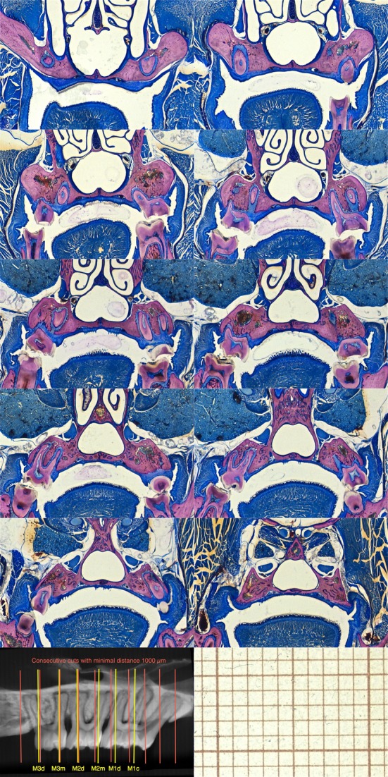
Consecutive histomicrographs every 1000 μm (red lines) of an undissected control rat. Some of the buccal roots were located between the cutting planes and thus do not appear on the sections. In most of the cases, it is not possible to evaluate both sides on the same section. MPR-aligned virtual slices located at lateral root prominences normally include the pulp chamber at the buccal bone level (M1c, M1d, M2m, M2d, M3m, M3d). At these sites dental parameters were evaluated (yellow lines).
In the following, standard procedures for histological processing of undecalcified tissues are outlined; emphasis is given on tissue block alignment and sawing longitudinal histological sections of the rat maxilla containing central sections of buccal roots of molars, based on information obtained by previous virtual tissue block alignment determination and cutting plane level definition on micro-CT data.
Tissue sample handling
After death, the maxillae were dissected free by means of a band-saw, and all orthodontic micro-appliances (Danz et al. 2013) were removed in order to avoid metal artifacts (beam hardening) during micro-CT registration. The tissue blocks had to be prepared adequately small to fit in a cylindric micro-CT sample-holder (10 mm in diameter) allowing scanning with a high resolution (12 μm). In addition, the blocks had to have standardized form and dimensions, ensuring preservation of the alignment during embedding and facilitating transfer of the virtual sectioning coordinates, when mounted in the cutting system in the laboratory. Thus, a cut perpendicular to the occlusal plane and the palatine raphe was made by means of a diamond band-saw at the mesial aspect of both M1, creating thereby a reference plane (RP), and with the specimens placed in a customized tissue sample-holder (SH-aligned) assuring standardization of cutting planes and block dimensions (Fig. 2). Each maxilla was further separated in two (left and right) pieces by incising the soft tissues with a scalpel along the palatine raphe and gently breaking the midpalatal suture (MPS).
Figure 2.
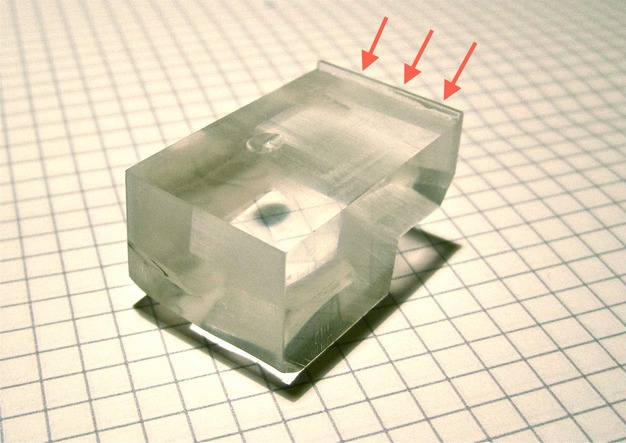
A custom sample-holder was used to align the samples. The maxilla was placed on the molars and the mesial aspects of the first molars were in contact with the anterior ridge (arrows), thereby creating an approximately perpendicular cut to the occlusal plane and the MPS with a diamond band-saw.
The resulting samples (i.e. hemi-maxillae) were then fixed by continuous submersion in 4% neutral-buffered formaldehyde (1 week) at +4°C, and then dehydrated by continuous submersion in ascending concentrations of alcohol (70%: 3 days; 95%: 3 days; 100%: twice within 2 days), and cleared by Xylol I and Xylol II (1 week each). Thereafter, the hemi-maxillae were placed in cylindric glass vials and secured with their RP parallel to the bottom of the bottle and embedded in polymethylmethacrylate (PMMA; 80% vol. methylmethacrylate : 20% vol. dibutyl phthalate; Merck Schuchardt OHG, Hohenbrunn, Germany) as follows: (i) infiltration phase: 7 days immersed in PMMA under constant movement at 4°C; (ii) polymerization phase: addition of 0.5 g per 100 mL catalyst (Perkadox 16; Dr Grogg Chemie AG, Stettlen, Switzerland) and after 7 days supplemented with 1 g per 100 mL catalyst. Polymerization took up to 4 days in a water bath assuring constant room temperature with sealed glasses and without movement. Thereafter, the polymerized PMMA blocks were further trimmed with an abrasive belt to a final maximal diameter slightly below 10 mm and approximately 12 mm in height.
Micro-CT imaging
Sets of six blocks were stapled vertically to fit in the cylindrical sample-holder (10 mm in diameter) for digitalization at a resolution of 12 μm by a Scanco 40 micro-CT scanner (Scanco Medical, Brüttisellen, Switzerland) and with the following settings: 70 kVp, 113 μA, integration time 2 × 200 ms, average data). The cylindric sample-holder was rotated (500 projections/180°) and moved incrementally during scanning to achieve isotropic voxel dimensions. The generated data were exported in a .tif-format, eight-bit grayscale 1024 × 1024 pixel resolution. To reduce the data amount for image processing, the software ImageJ, version 1.43u, was used then to crop the image stacks to the volume containing all data of each MMA-block. The cropped data were further saved as a .raw document, manually imported in Osirix v.3.9.4 64-bit (Pixmeo Sàrl, Geneva, Switzerland) and the spatial calibration was set to 12 μm.
By scrolling through the original SH-aligned stack of micro-CT sections of each block, the RP, the cutting plane and the level of every facial root were defined. The original SH-aligned micro-CT image stack was duplicated and virtually realigned using a MPR reconstruction (MPR-aligned). The reference structures for the alignment were the MPS for the sagittal plane and the furcations for the transverse plane, which is equal to the SH-alignment, but based on hard tissues (Danz et al. 2013). Because some roots may be slightly oblique to the RP and not completely parallel to each other, and because realignment of the mounted block for every root during the histological processing would not only be extremely cumbersome, but also include unnecessary tissue loss and introduce distortion in the measurements of tooth position relative to the MPS, the following compromise was accepted: the cutting plane and level of every facial root were defined in the SH-aligned and the MPR-aligned image stacks so as to include the pulp chamber at bone level and most of the root canal length; hence, some roots could appear slightly shorter than their actual length. The distances of the thus-defined cutting planes from the RP in the SH-aligned image stacks were then calculated separately for each root, for example, RP distance to the center of the distobuccal root of M3 (RP–M3d), RP distance to the center of the mesiobuccal root of M3 (RP–M3m), etc. In a third method, the median distances from each RP to the block bottom were calculated, and an additional slice (median slice) at each median distance from the SH-aligned image stacks for each block was taken.
Transfer of the virtual sectioning coordinates
The set-up used in the preset study included a free standing sectioning machine (saw microtome Meprotech, Medeja, Assendelft, the Netherlands) and a desktop grinding-polishing unit (Exakt; Exakt Apparatebau GmbH, Norderstedt, Germany). The cutting machine consisted of a horizontal, diamond-coated, rotating cutting disk (250 μm thick), and a vertical sample-holder. The vertical sample-holder is moved towards the cutting disk by means of an electronically controlled arm (feed-rate 0.008 mm s−1), and the system allows speed control (speed 1800 rpm) of both the rotating diamond and the moving arm through a digital control panel. The height of the sample-holder is manually adjusted by a rotating knob, based on a rack and pinion assembly; distance changes are displayed on the digital control panel.
The virtual sectioning coordinates of the SH-aligned micro-CT sections, determined above, were transferred to the specimen block–cutting system set-up as follows. The side of the specimen block representing the RP was glued with cyanoacrylate on the freshly cut surface of a PMMA block, used as sample-holder. In this way, the specimen block was positioned with its RP plane parallel to the cutting disk and, in addition, a ‘zero (cutting) level' was determined. The specimen-holder arm was then lowered further so that the diamond blade was set at a level representing the RF–M3d distance calculated based on the micro-CT data, plus the anticipated section thickness (200 μm), the amount of tissue loss thickness (i.e. cutting disk thickness; 300 μm) and some additional safety distance (100 μm). A first cut was made at that level to remove the excess part of the block. Thereafter, the specimen-holder arm was raised at a distance equal to the section thickness plus the cutting disk thickness and a new cut was made. Thus, this cut generated a section including the central aspect of the distobuccal root of M3. In a similar way, by further raising the specimen-holder arm according to the distances calculated before, additional sections representing central aspects of the rest of the relevant buccal roots were obtained.
The sections were polished with sandpapers No. 1000 and 4000 mounted on the rotating stage of the polishing unit and stained with basic fuchsin, toluidin blue and dinatriumtetraborat (basic fuchsin 0.3 g per 100 mL, toluidin blue 1 g and dinatriumtetraborat 1 g per 100 mL).
Morphometrical evaluation
Histological slices were digitalized with an Olympus BX51 microscope (2 × optical magnification; resolution 236.0 pixel mm−1 horizontal × 234.4 pixel mm−1 vertical; eight-bit color).
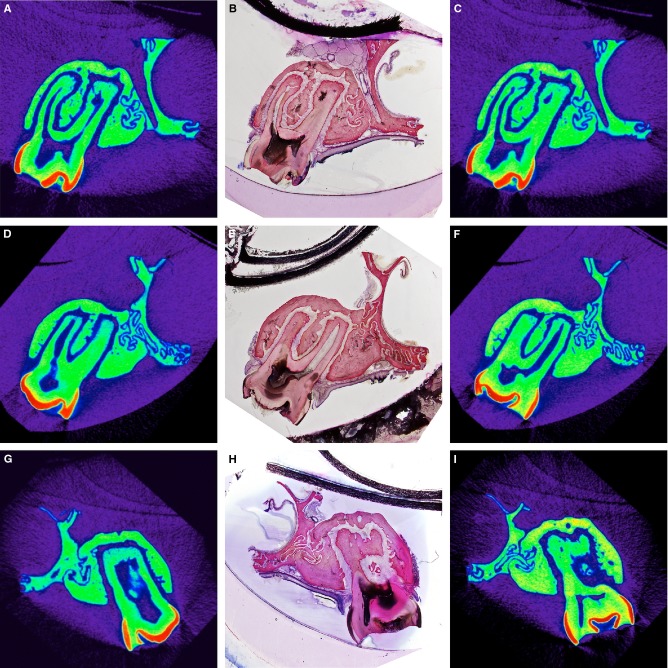
To evaluate the accuracy of virtual section coordinate transfer, the position of the obtained histological section level was located within the stack of micro-CT images by visually comparing the hard tissues in the two types of sections, and then its distance to the SH-aligned micro-CT section level was calculated (Fig. 3). Differences between the cutting planes of the obtained histological section and the corresponding virtual cutting planes defined in the micro-CT data were analyzed by the Bland–Altman method.
Figure 3.
SH-aligned micro-CT sections, the corresponding histomicrographs, and the relocated micro-CT sections from three specimens. The virtual cutting plane was defined to include the pulp chamber at the buccal bone level and most of the root canal length of the buccal root (A, D, G). After processing, the plane of the resulting histological section (B, E, H) was visually identified within the micro-CT data, representing the relocated micro-CT section (C, F, I) by comparing hard-tissue appearance and choosing the most resembling slice (i.e. B–C or E–F or H–I). Differences in cutting plane level between the intended and relocated SH-aligned micro-CT slice, herein, were 36 μm (A–C), −204 μm (D–F) and −312 μm (G–I). Gray values in micro-CT sections (resolution: 12 μm) are displayed in a NIH color look-up table to enhance contrast.
Interactive geometrical constructions, as described elsewhere (Danz et al. 2013), were applied on SH-aligned histomicrographs and MPR-aligned virtual micro-CT sections using the software Archimedes Geo3D, v1.3.6 (Raumgeometrie.de, Göttingen, Germany), and calibration was checked by measuring an image-stamped reference distance. The following parameters were estimated: (i) tooth position = distance of the root center (RC) to the lower corner of the MPS; (ii) tooth inclination = angle between the tooth axis and the line through RC and MPS (Fig. 4). In order to evaluate asymmetries (natural asymmetries and due to the splitting procedure), comparisons between the right and left maxillae (for both the MPR-aligned virtual micro-CT sections and for the SH-aligned histomicrographs) were performed.
Figure 4.
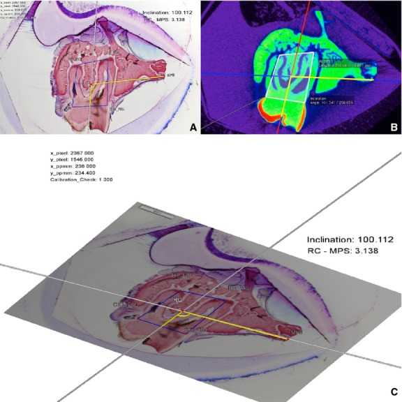
MPR-aligned virtual micro-CT section (A) and the corresponding histomicrograph of the obtained section (B). The same measurements made on micro-CT and histomicrographs were compared to evaluate methodological errors and differences between the methods regarding tooth position and inclination. (C) 3D display of the interactive geometrical construction by the software DreiDEdit Archimedes Geo 3D.
Furthermore, the drop-outs of sections obtained by the three different methods, i.e. the median micro-CT section, MPR-aligned virtual micro-CT section, and the resulting SH-aligned histological section, were compared. A slice was considered a drop-out when the geometrical constructions were not applicable due to absence of the anatomical landmarks and/or a clearly mispositioned cut.
The distortional effects due to imprecise alignment to the axis of the specimen were analyzed by comparing tooth position and tooth inclination for both methods (MPR-aligned virtual micro-CT section vs. SH-aligned histomicrograph).
All random errors were assessed by duplicate evaluations on 20 randomly selected pairs of sections registered 3 months apart, using the Bland–Altman method difference vs. average (Bland & Altman, 1999), the interclass correlation coefficient (ICC) one-way random effects model, and the method of moments estimator (MME; Ingervall, 1964; Springate, 2011). Random section selection was done by list randomization on http://www.random.org. The accuracy and precision of metric (i.e. tooth position) and angular (i.e. inclination) measurements were assessed separately for the MPR-aligned virtual micro-CT sections and for SH-aligned histomicrographs on duplicate measurements. The statistical software packages GraphPad Prism v5.00 (GraphPad Software, San Diego, CA, USA) and SPSS v19 (IBM Corporation, Armonk, NY, USA) were used.
Results
Accuracy of virtual section coordinate transfer with SH-alignment
Some discrepancy between the obtained histological section level and the SH-aligned virtual level was observed (95% limit of agreement −402 to 105 μm). In general, the obtained histological section level was located slightly lower (i.e. towards the RP) than the SH-aligned virtual level (median = −148 μm; Fig. 5).
Figure 5.
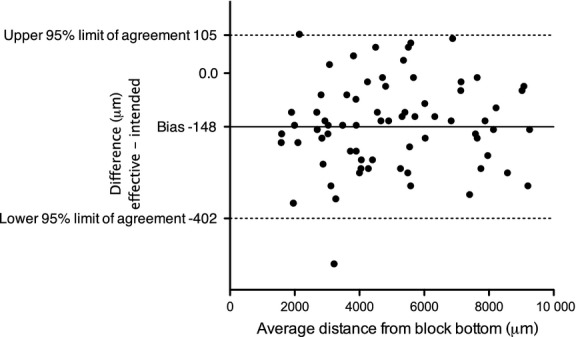
Bland–Altman comparison between the MPR-aligned virtual micro-CT section level and the obtained histological section level, evaluating the accuracy of virtual section coordinate transfer. The obtained histological section level tended to be located closer (on average, 148 µm) to the RP than the MPR-aligned virtual micro-CT section level.
The random error of evaluation of the accuracy of virtual section coordinate transfer was within −69.5 to 52.7 μm (95% limit of agreement) with a bias of −8.4 μm [ICC 1.000, 95% confidence interval (CI) −1.000 to 1.000; MME 11.0 μm, 95% CI 6.0–16.1 μm].
Analysis of differences between left and right hemi-maxillae (natural asymmetries and splitting procedure)
For MPR-aligned virtual micro-CT sections, the difference between the right and left sides was −19.5 μm with a 95% limit of agreement (LA) of −225.7 to 186.7 μm, and for the obtained histomicrographs it was −20.0 μm with a 95% LA of −212.6 to 172.6 μm (Fig. 6).
Figure 6.
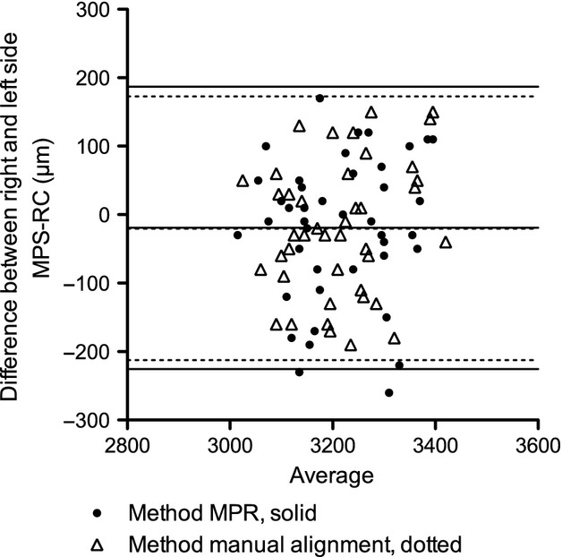
Bland–Altman comparison between right and left side tooth position (RC–MPS) measured on the MPR-aligned virtual micro-CT section and on the histomicrographs.
Comparison of drop-outs between methods
Two histomicrographs out of 84 were excluded from further analysis because the slice was partially destroyed after histological processing, and therefore the geometrical constructions for tooth position and inclinations were not applicable. Using median RP-root distance values for defining the section level (median micro-CT sections) caused a drop-out of 67.9% (57 out of 84 sections); on the contrary, the drop-out in the histomicrographs was 2.4% (two out of 84 sections). Obviously defining the sectioning level individually for each collected root in each block (SH-aligned and MPR-aligned virtual micro-CT sections) was successful in all 84 slices.
Effects of imprecise alignment: error between MPR-aligned virtual micro-CT sections and SH-aligned histomicrographs
A bias of 20.5 μm (95% LA −114.1 to 155.1 μm) was found for tooth position (i.e. RC–MPS) and −0.5° (95% LA −8.4 to 7.2°) for inclination between the methods. Zero was within LA for tooth position as well as for inclination, and the differences of the methods were not statistically significant (Wilcoxon signed-rank test P(RC–MPS) = 0.37 and P(inclination) = 0.20).
Error of metric and angular duplicate measurements on MPR-aligned virtual micro-CT sections and SH-aligned histomicrographs
For duplicate measurements on MPR-aligned virtual micro-CT sections, the random error for tooth position was within −97.6 to 81.6 μm (95% LA) with a bias of −8 μm (ICC 0.967, 95% CI 0.919–0.987; MME 16.4 μm, 95% CI 8.7–23.1 μm), and for inclination within −2.93 to 3.43° (95% LA) with a mean bias of 0.25° (ICC 0.968, CI 0.920–0.987; MME 0.58°, 95% CI 0.31–0.82°).
For duplicate measurements on SH-aligned histomicrographs, the random error for RC–MPS was −62.3 to 59.1 μm (95% LA) with a bias of −1.6 μm (ICC 0.986, 95% CI 0.966–0.995; MME 10.4 μm, 95% CI 5.5–14.6 μm), and for inclination within −1.68 to 2.24° (95% LA) with a bias of 0.28° (ICC 0.988, 95% CI 0.971–0.995; MME 0.37°, 95% CI 0.19–0.52°). Comparing the variances of the differences between duplicate measurements on MPR-aligned virtual micro-CT sections and SH-aligned histomicrographs, no significant differences regarding RC–MPS (P = 0.0613) were observed; however, significant differences regarding inclination P = 0.0401 were found.
Normal anatomy of the rat periodontium
The analysis of the histomicrograph (Figs 7 and 8) containing the maxilla including the distal root of the second molar reveals a rat's periodontium, which is overall quite similar to that in humans. One difference is that the keratinized gingival epithelium bends apical and joins the junctional epithelium. The vestibulum appears quite shallow with muscular tissue of the musculus buccinator extending coronally almost to the buccal alveolar bone level. The marginal periodontium includes dento-gingival and dento-periosteal fibers similar to human anatomy (Lindhe et al. 2008; Fig. 3). The maxillary bone is compact and interspersed with lacunae of osteocytes and compartments of Haversian systems forming layers of intracortical new bone. Superficial layers of newly formed bone can be found on vestibular aspects of the vestibular bone plate, the palatal shelf. The maxillo-palatine and the intermaxillary sutures show alternating areas of resorption and apposition. Fresh apposition of root cementum was thickest at the apex of the roots.
Figure 7.
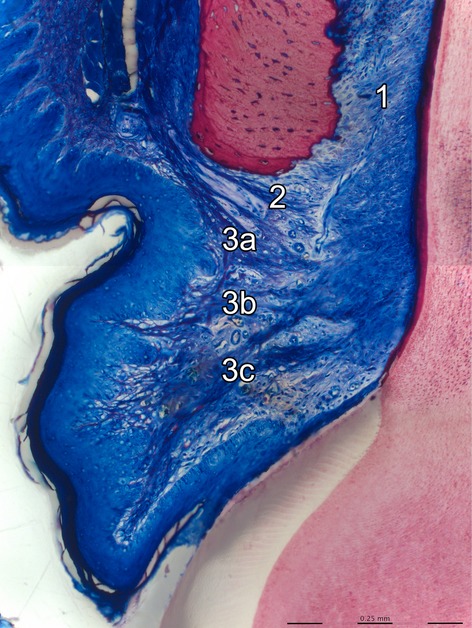
The histomicrograph shows the buccal aspect of the coronal periodontium of a rat molar. The periodontal ligament (1) and the supracrestal gingival fiber-network [dentoperiosteal fibers (2), apical (3a), horizontal (3b) and coronal (3c) dentogingival fibers] are clearly visible in dark blue color (basic fuchsin, toluidin blue and dinatriumtetraborat staining).
Figure 8.
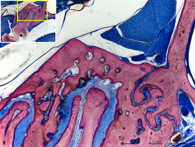
In rats most of the maxillary bone is compact. Some minor portions of cancellous bone are present in central aspects of the maxilla. Areas of remodeling are found on vestibular and coronal aspects of the buccal bone plate, the oral aspect of the palatal shelf, at the apex of roots (see also Fig. 1).
Discussion
The current report describes a new method to produce histological sections from small specimens, in particular longitudinal histological sections of the rat maxilla containing central aspects of buccal roots of molars, by means of tissue block alignment with a sample-holder and virtual cutting plane level definition in micro-CT-generated images and subsequent transfer of this information to the cutting system in the laboratory. The histomicrographs obtained by this new method were compared with virtually aligned micro-CT sections.
The transfer of the virtual section coordinates as described herein was found to be rather accurate, as the cutting plane of the obtained histological sections deviated, in general, only slightly (approximately 150 μm) from the intended SH-aligned virtual cutting plane. The possibility that this minor deviation was a matter of pure chance cannot be excluded; nevertheless, this deviation was in the vast majority of cases towards the same direction (i.e. slightly lower than the virtual cutting plane), suggesting a systematic error. The safety distance was included, because an average slack of such magnitude of the specimen-holder height-adjustment mechanism, when changing the direction of the movement (rising vs. lowering), was observed in the present equipment during piloting of the cutting procedures.
On the other hand, the systematic error between both tested methods (MPR-aligned virtual micro-CT section vs. SH-aligned histomicrograph) of metric (tooth position) and angular (inclination) histomorphometrical measurements does not seem to have any important negative effect, as the observed differences were not only statistically insignificant, but also numerically very small to have any (clinical) relevance (20.5 μm and 0.5°, respectively). The random error between both methods was acceptable (95% LA range of 269 μm for RC–MPS and 15.6° for inclination) and approximately the double of the random error of duplicate measurements within the methods (micro-CT: 95% LA range of 179 μm for RC–MPS and 6.4° for inclination; histomicrographs: 95% LA range of 121 μm for RC–MPS and 3.9° for inclination).
When longitudinal histological sections of the maxilla containing central aspects of buccal roots of rat molars are needed, except from determining the cutting plane level within the tissue block in order to ‘hit' the root, another important point regards the angle of the cutting plane with the long axis of the maxilla. Divergence of the cutting plane from the long axis of an object results in distortion of the object in one direction and overestimation of dimensions (Parfitt et al. 1987). Large bucco-palatal divergence of the cutting plane from the long axis of the maxilla herein would have resulted in overestimation of the RC–MPS distance. More specifically, divergence of the cutting plane from the long axis of the maxilla of up to 8° would have caused 1% distortion in RC–MPS distance, which is approximately equal to the random measurement error observed in the histomicrographs herein, and would have thus been acceptable. In perspective, misalignment of the specimen block of more than 8° divergence from the maxillary long axis seems unlikely with the presented methods.
A simpler way to evaluate orthodontic/orthopedic expansion and its impact on the periodontal tissues would have been obtaining a section with a single cut through the right and left sides of the maxilla, so that both sides of the jaw would be visible on the same histological section. Nevertheless, such a section would not always include central aspects of the same facial roots of both sides, simply due to small morphological asymmetries between right and left sides of the dento-alveolar complex. Therefore, in the present study, the maxillae were separated along the MPS. By doing this, informational loss due to miscutting during histological processing was minimized and tissues were adequately small allowing micro-CT scanning with 12 μm resolution. The 95% range of agreement of side differences is approximately double that from the random measurement error. In other words, the splitting procedure increases the 95% range of agreement less than the amount of the random error, because side differences arise not only from unequal splitting and meandric suture form, but also from natural side differences. Thus, splitting of the maxilla by gently breaking the MPS seems to be an acceptable procedure for unilateral evaluation.
It is acknowledged that access to micro-CT equipment is not available in every hard-tissue laboratory, and thus the present method may not have widespread applicability. A simpler approach would be measuring from the bottom of the block (RP) to the center of the root on standard periapical (dental) X-rays (possibly under magnification) for defining section level and plane. Yet another approach would be to exclude any radiographic technique and use a visual approach, where the plastic embedded specimens are carefully grinded under continuous inspection with a stereomicroscope, until the desired plane and section level is achieved. Such an approach would be of course rather cumbersome and would need excellent craftsmanship of the operator. Nevertheless, because in the present evaluation no ‘control group' in the sense of one of the above alternative techniques was used, it is acknowledged that no unequivocal conclusions on the superiority of the proposed method can be drawn.
In the present study, the Bland–Altman method was used to evaluate differences between various parameters and display these differences using a graph. The application of the Bland–Altman method to quantify methodological errors is easy to read as an upper range with units is calculated, in which the error can be expected, and at the same time bias is tested. An alternative method for this evaluation could be the ICC; ICC, however, does not provide units or absolute values and is thus more difficult to interpret. The MME is the simplest method used in this paper to quantify errors, but it lacks graphical display. Another advantage of the Bland–Altman method vs. ICC or MME is that mean bias has a direction (plus/minus).
The periodontium of the rat is quite similar to the human periodontium (Schroeder, 1986), with the exception that the gingival epithelium bends apical and joins the non-keratinized junctional epithelium (Schroeder, 1986), and that rat periodontal anatomy and physiology seem to be more robust compared with humans. Functional adaptation to mechanical stimuli by subperiostal bone apposition in rat femurs was reported to be more pronounced in rats compared with humans (Bagi et al. 1997), and periodontal disease studies are limited to oral flora investigations, because rats do not show easily periodontal lesions (Navia & Lopez, 1977). Layers of recently formed bone and cementum confirm tissue remodeling after adolescence, such as: eruption of molars in rats (Hoffman & Schour, 1940; Sicher & Weinmann, 1944) and humans (Iseri & Solow, 1996); continuous apposition of cementum and bone in rats (Hoffman & Schour, 1940) and humans (Lauretani et al. 2008); increasing root length (Hoffman & Schour, 1940); wear of the teeth and decreasing height of the anatomical crown (Hoffman & Schour, 1940); and increase in weight. It has been previously reported that the supra alveolar gingival fibers in the rat are less developed than in the human (Reitan & Kvam, 1971). Our findings in contrast show rather well-developed supra alveolar fibers.
In conclusion, the method of transferring virtual tissue block alignment data to the sawing system in the laboratory for the production of histological sections presented herein seems to be rather efficient and accurate in producing histological sections of buccal roots of rat maxillary molars. The high methodological standardization in this method ensures retrieval of histological slices of interest with excellent display of anatomical microstructures, in a reproducible manner, minimizes random errors, and thereby may contribute to the reduction of the number of animals needed.
References
- Bagi CM, Wilkie D, Georgelos K, et al. Morphological and structural characteristics of the proximal femur in human and rat. Bone. 1997;21:261–267. doi: 10.1016/s8756-3282(97)00121-x. [DOI] [PubMed] [Google Scholar]
- Bland JM, Altman DG. Measuring agreement in method comparison studies. Stat Meths Med Res. 1999;8:135–160. doi: 10.1177/096228029900800204. [DOI] [PubMed] [Google Scholar]
- Bosshardt DD, Bergomi M, Vaglio G, et al. Regional structural characteristics of bovine periodontal ligament samples and their suitability for biomechanical tests. J Anat. 2008;212:319–329. doi: 10.1111/j.1469-7580.2008.00856.x. [DOI] [PMC free article] [PubMed] [Google Scholar]
- Bosshardt DD, Sculean A, Windisch P, et al. Effects of enamel matrix proteins on tissue formation along the roots of human teeth. J Periodontal Res. 2005;40:158–167. doi: 10.1111/j.1600-0765.2005.00785.x. [DOI] [PubMed] [Google Scholar]
- Danz JC, Dalstra M, Bosshardt DD, et al. A rat model for orthodontic translational expansive tooth movement to investigate its effect on the periodontium. Orthod Craniofac Res. 2013;16:223–233. doi: 10.1111/ocr.12025. [DOI] [PubMed] [Google Scholar]
- Dorph-Petersen KA, Nyengaard JR, Gundersen HJ. Tissue shrinkage and unbiased stereological estimation of particle number and size. J Microsc. 2001;204:232–246. doi: 10.1046/j.1365-2818.2001.00958.x. [DOI] [PubMed] [Google Scholar]
- Hoffman MM, Schour I. Quantitative studies in the development of the rat molar. I. The growth pattern of the primary and secondary dentin (from birth to 500 days of age) Anat Rec. 1940;78:233–251. [Google Scholar]
- Ingervall B. Retruded contact position of mandible. A comparison between children and adults. Odontol Revy. 1964;15:130–149. [Google Scholar]
- Iseri H, Solow B. Continued eruption of maxillary incisors and first molars in girls from 9 to 25 years, studied by the implant method. Eur J Orthod. 1996;18:245–256. doi: 10.1093/ejo/18.3.245. [DOI] [PubMed] [Google Scholar]
- Kiernan JA. Histological and Histochemical Methods. Bloxham: Scion; 2008. pp. 24–126. [Google Scholar]
- Lauretani F, Bandinelli S, Griswold ME, et al. Longitudinal changes in BMD and bone geometry in a population-based study. J Bone Miner Res. 2008;23:400–408. doi: 10.1359/JBMR.071103. [DOI] [PMC free article] [PubMed] [Google Scholar]
- Lindhe J, Lang NP, Karring T. Clinical Periodontology and Implant Dentistry. Oxford: Wiley-Blackwell; 2008. pp. 22–23. [Google Scholar]
- Navia JM, Lopez H. Sources of variability in rat caries studies: weaning age and diet fed during tooth eruption. J Dent Res. 1977;56:222–227. doi: 10.1177/00220345770560030501. [DOI] [PubMed] [Google Scholar]
- Parfitt AM, Drezner MK, Glorieux FH, et al. Bone histomorphometry: standardization of nomenclature, symbols, and units. Report of the ASBMR Histomorphometry Nomenclature Committee. J Bone Miner Res. 1987;2:595–610. doi: 10.1002/jbmr.5650020617. [DOI] [PubMed] [Google Scholar]
- Reitan K, Kvam E. Comparative behavior of human and animal tissue during experimental tooth movement. Angle Orthod. 1971;41:1–14. doi: 10.1043/0003-3219(1971)041<0001:CBOHAA>2.0.CO;2. [DOI] [PubMed] [Google Scholar]
- Schroeder HE. The Periodontium. Berlin: Springer; 1986. pp. 71–106. [Google Scholar]
- Sicher H, Weinmann JP. Bone growth and physiologic tooth movement. Am J Orthod Oral Surg. 1944;30:109–132. [Google Scholar]
- Springate SD. The effect of sample size and bias on the reliability of estimates of error: a comparative study of Dahlberg's formula. Eur J Orthod. 2011;34:158–163. doi: 10.1093/ejo/cjr010. [DOI] [PubMed] [Google Scholar]


