Abstract
The aim of this study was to introduce bioactivity to the electrospun coating for implantable glucose biosensors. Coaxial fibre membranes having polyurethane as the core and gelatin as the shell were produced using a range of polyurethane concentrations (2, 4, 6 & 8% wt/v) while keeping gelatin concentration (10% wt/v) constant in 2,2,2-trifluoroethanol. The gelatin shell was stabilized using glutaraldehyde vapour. The formation of core-shell structure was confirmed using TEM, SEM and FTIR. The coaxial fibre membranes showed uniaxial tensile properties intermediate to that of the pure polyurethane and the gelatin fibre membranes. The gelatin shell increased hydrophilicity and glucose transport flux across the coaxial fibre membranes. The coaxial fibre membranes having small fibre diameter (541 nm) and a thick gelatin shell (52%) did not affect the sensor sensitivity, but decreased sensor’s linearity in the long run. In contrast, thicker coaxial fibre membranes (1133 nm) having a thin gelatin shell (34%) maintained both sensitivity and linearity till 84 days of the study period. To conclude, polyurethane-gelatin co-axial fibre membranes, due to their faster permeability to glucose, tailorable mechanical properties and bioactivity are potential candidates for coatings to favourably modify the host responses to extend the reliable in vivo lifetime of implantable glucose biosensors.
Keywords: Coaxial polyurethane/gelatin fibrous membrane, implantable biosensor coatings, electrospun coatings, glucose biosensor, glucose diffusion
1. Introduction
Reliable continuous monitoring of physiologically relevant molecules using implantable sensors is a longstanding challenge. As soon as the sensor is implanted in the body, it starts losing sensitivity, which downward drift caused by biofouling and fibrous encapsulation continues rapidly until the sensor fails. Many strategies involving surface modifications or deposition of additional polymeric coatings have been developed to combat the effects of biofouling, fibrous encapsulation and blood vessel regression [1]. Nevertheless, reliable extension of the in vivo sensing lifetime of implantable glucose biosensors is yet to be achieved.
In our research, we apply electrospinning technology towards overcoming the limitations of the traditional strategies to extend the in vivo sensing lifetime of implantable sensors. Recently, we demonstrated that efficacy of electrospun polyurethane (PU) coatings as mass-transport limiting membranes for miniature coil-type glucose biosensors [2, 3]. Compared to the traditional solvent cast membrane, electrospun PU membrane showed advantages in having tailorable thickness, structure and composition, as well as having minimal effect on sensor sensitivity and function. The membranes were tested for mass-transport limiting, and had subcellular porosity. Hence they are susceptible to biofouling and fibrous encapsulation. An additional tissue engineering layer would be essential to overcome this problem, which again can be achieved using electrospinning technology. Our strategy is to electrospin coaxial fibres having bioactive gelatine (GE) as the sheath and PU as the reinforcing core.
The synthetic polymer, PU has the desirable mechanical properties for implantable biomedical device applications, but is relatively inert. In contrast, extracellular matrix derivatives, collagen and gelatin are bioactive, but lack the desired mechanical properties. Electrospinning provides an opportunity to produce co-axial fibres with core-shell structure made from different types of synthetic and natural materials that offer combined properties, e.g., bioactivity and mechanical strength. Recently, electrospun materials due to their similarity in 3D structure to native extracellular matrix (ECM) have been of particular interest for tissue engineering [4–7]. Polycaprolactone (PCL)-gelatin core-shell electrospun fibres were produced to achieve comparable maximum elongation with PCL [4]. Likewise, PCL-collagen coaxial fibres were reported to have the advantage of resembling the natural ECM compared to the rough collagen coating on the pristine PCL through encouraging cell-matrix interaction [5]. C-poly (lactic-co-glycolic acid)/chitosan membranes were found to have potential in controlling drug release and skin restoration [6]. Similarly, collagen functionalized thermoplastic PU scaffolds were also developed for soft tissue engineering application [7]. Therefore, it is hypothesised that introduction of a thin layer of natural biopolymer, e.g. gelatin on PU fibres with a controllable diameter and porous structure can be used as coatings for favourably modifying host responses to implantable biosensors. However, the additional membrane for engineering the tissue responses would in turn also further decrease the pre-implantation sensitivity of the implantable biosensor.
The objective of this study was to optimize the parameters for electrospinning PU core-gelatin shell coaxial fibres, characterize them, apply directly on model coil-type implantable glucose biosensors and evaluate their effects on in vitro sensor function. A specialised spinneret, made of concentric tubes connected to two separate fluid sources, such that coaxial fibres can be electrospun, was designed and manufactured. The solution and the process parameters for electrospinning coaxial fibres were varied. The gelatin shell was stabilized by crosslinking. The membranes were characterised for morphology, pore sizes, porosity, hydrophilicity, solute diffusion, chemical and mechanical properties. Glucose biosensors were then coated with optimized co-axial fibre membranes and their effects on sensor function evaluated.
2. Materials and Methods
Thermoplastic PU (Selectophore™), gelatin from porcine skin (type A), tetrahydrofunan (THF), N,N-dimethylformamide, 2,2,2-trifluoroethanol (TFE) (≥99.0 % (GC)), bovine serum albumin, glutaraldehyde grade I (50 %), glucose oxidase (GOD) (EC 1.1.3.4, Type X-S, Aspergillus niger, 157,500 U/g, Sigma), ATACS 5104/4013 epoxy adhesive, Brij 30, D-(+)-glucose and 0.01 M phosphate buffered saline (PBS) tablets were purchased from Sigma–Aldrich–Fluka. Teflon-coated platinum–iridium (Pt/Ir) (9:1 in weight, Ø 0.125 mm) and silver wires (Ø 0.125 mm) were obtained from World Precision Instruments, Inc. (Sarasota, FL).
2.1. Glucose biosensors
A miniature coil-type implantable glucose biosensor was used as model sensor in this study [2, 8–10]. The amperometric sensor is a two electrode system based on Pt/Ir working electrode with immobilised GOD enzyme and silver/silver chloride (Ag/AgCl) reference electrode. The procedures for sensor manufacture are based on our previous reports [2, 8–10].
2.2. Electrospinning coaxial PU/gelatin fibres
To spin co-axial fibres, a coaxial spinneret was custom-made. It consisted of a stainless steel Tee-Union (1/8″ Swagelok, UK), a PTFE union set (1/16″, a PTFE union, two PTFE cones and two PEEK adaptors), and two stainless steel concentric tubes that allow coaxial extrusion of two fluids simultaneously. The inner tube has an inner diameter of 0.508 mm and an outer diameter of 0.711 mm, while the outer tube has an inner diameter of 2.88 mm and an outer diameter of 3.0 mm. The electrospinning setup utilized for this study was described earlier [2, 3]. The coaxial spinneret was mounted vertically above a grounded steel plate (collector, 16×16 cm2). Two syringe pumps (Fusion 100) were used to pump inner/outer polymer feed solutions in 10 ml plastic syringes (BD, Oxford, UK). In this study, a fluorinated alcohol, TFE (100%), was used as the solvent for both gelatin (shell) and PU (core). The gelatin was dissolved in TFE under continuous stirring at room temperature for at least 10 h. PU solutions of different concentrations (2, 4, 6, and 8 w/v%) were also prepared in TFE at room temperature, under continuous stirring for 6 h. Dynamic viscosity of the TFE solvent, different PU and gelatin solutions were measured using Automated Micro Viscometer (AMVn, Anton Paar, St Albans, UK). For spinning co-axial fibres, gelatin and PU solutions were separately fed to the outer and the inner needles of co-axial spinneret simultaneously, using two programmed syringe pumps through 1/8″ OD and 1/16″ OD PTFE tubing with the feed rate of 1.2 ml/h and 0.8 ml/h respectively. Applied voltage between 11.25–14 kV and a tip-to-collector distance of 15 cm were used to ensure the formation of a steady coaxial jet with an external meniscus surrounding the inner one ejecting from a stable Taylor Cone for the different PU solution concentrations with gelatin concentration kept constant at 10 w/v%. The fibres were spun at ambient room temperature (20±2°C) and humidity (40±5 %).
2.3. Crosslinking of gelatin
The gelatin, being water soluble, needs stabilization by crosslinking to maintain the co-axial fibre structure. Two methods were tested for glutaraldehyde crosslinking of the gelatin sheath of the co-axial fibres. First, the coaxial fibre membranes on aluminium (Al) foils were immersed in aqueous glutaraldehyde (25% solution diluted with DI water at 1:99 volume), under continuous shaking for 12 hours at room temperature. The membranes were washed in several changes of DI water, dried over night at 40°C and then stored in a vacuum desiccator until further use. Secondly, glutaraldehyde crosslinking of gelatin was achieved by incubating the co-axial fibre membranes on Al foils in a vacuum desiccator with the desiccant replaced by 10 ml of 25% aqueous glutaraldehyde solution (in a petri dish) for 3 days at room temperature. The samples were then transferred to a power-assisted vacuum desiccator for removal of excess glutaraldehyde and stored in desiccator until further use.
2.4. Electrospinning co-axial fibres directly on sensor surface
A dynamic collector configuration reported in our previous study [2], was used for electrospinning coaxial fibres directly on sensor surface, wherein the sensor was inserted in 0.5 inch stainless steel needle (23 G blunt-tip) and the needle fixed at the end of a custom-made rotator. A rotation speed between 660 –690 rpm, obtained by setting both voltage and current constant at 5 V and 0.11 A respectively, was chosen to obtain random orientation of the electrospun fibres.
Two types of PU-gelatin coaxial fibrous membranes (ESC) were electrospun both on sensors (Pt-GOD) coated with epoxy-PU (EPU) semi-permeable membrane (Pt-GOD-EPU-ESC) [2] and those without (Pt-GOD-ESC) to study the ability of coaxial-fibre membranes as mass-transport limiting membranes. The designations and electrospinning conditions for co-axial fibre membranes spun directly on the sensor surface are summarised in Table 1. The glutaraldehyde crosslinking of gelatin in the co-axial fibres was achieved by incubating the sensors in vacuum desiccator saturated with glutaraldehyde fumes as described above (section 2.3). Six sensors per electrospinning coating configuration (Pt-GOD-EPU-ESC or Pt-GOD-ESC) were tested for in vitro functional efficacy and six sensors without any electrospun coatings (Pt-GOD-EPU) used as controls.
Table 1.
Electrospinning conditions used for spinning coaxial PU-gelatin fibres directly on biosensor surface
| Designation | Concentration (w/v %) | Voltage (kV) | Feed (ml/h) | Rate | Distance (cm) | |
|---|---|---|---|---|---|---|
| PU | GE | PU | GE | |||
| Pt-GOD-EPU-6PU10GE | 6 | 10 | 13.25 | 0.8 | 1.2 | 15 |
| Pt-GOD-6PU10GE | ||||||
| Pt-GOD-EPU-2PU10GE | 2 | 10 | 14 | 0.8 | 1.2 | 15 |
| Pt-GOD-2PU10GE | ||||||
2.5. Characterization of electrospun membranes
2.5.1. Infrared spectroscopy
An ATR-FTIR spectrophotometer (PerkinElmer Inc.) was used to verify the core-shell fibre structure of electrospun coaxial fibres. Each spectrum, acquired in transmittance mode, was an average of 128 scans at a resolution of 4 cm−1.
2.5.2. Core-shell structure of the fibres and morphology of the membranes
Transmission electron microscope (TEM, HITACHI H-600) was used to examine its coaxial structure, with an accelerating voltage of 100 kV. The samples for TEM observations were prepared by collecting the nano-fibres onto carbon-coated Cu grids. The electrospun membranes were also sputter coated for 30 sec with gold using an AGAR high-resolution sputter-coater and observed under a field emission scanning electron microscope (FESEM, Zeiss Supra 35 VP) in SE mode for morphology.
2.5.3. Fibre diameter and membrane thickness
The fibre diameters were measured on SEM images using a user friendly application developed in-house using Matlab for length measurements. A total of 160 measurements were made on 8 different SEM images, each representing a non-overlapping random field of view for each electrospun membrane configuration. To obtain the fine cross section images for the electrospun membranes (both sheets and on sensors), the membranes were snap-frozen in liquid nitrogen, and then cut using a scalpel. The resulting samples were processed for SEM and oriented appropriately to obtain image of cross-sections of the membranes. The above-mentioned software for diameter measurements was also used to measure the thicknesses of the membrane using SEM images of their cross-sections. The thickness of the electrospun membranes were also measured using a digital micrometer having a resolution of 0.001 mm. The membranes were sandwiched between two slides and their thickness determined by subtracting the glass slides’ thickness.
2.5.4. Pore size and Porosity
The pore size for the different membranes was measured using extrusion porosimetry (also called bubble point measurement) as reported earlier in details [3, 11]. The range of pore sizes (radius α) was calculated using the Young-Laplace Eq. 1:
| (Eq. 1) |
where ΔP is the differential pressure, γst the surface tension of the wetting liquid and θ the wetting angle, which for a completely wetted membrane is 1 [11]. This is valid if it meets the conditions described in [3], which also set a contact angle (θ) at a value of 0.94 (cos 20°).
The porosity of the membranes was also determined using gravimetry as described earlier using the following equations:
| (Eq. 2) |
| (Eq. 3) |
where m = the mass of the membrane (g), d = the thickness of the membrane (cm), A= the area of nano-fibrous mat (cm2), ρb = the bulk density of materials (g/cm3). ρb was estimated using by Eq. 4:
| (Eq. 4) |
Where r is PU core radius, R the total fibre radius (measured using SEM), and ρPU and ρGE are the bulk densities of PU (1.04 g/cm3 as reported by manufacturer) and crosslinked gelatin (GE) respectively (1.369 g/cm3) [12].
2.5.5. Uniaxial tensile testing
A 40 min electrospinning time was used to obtain membranes thick enough for easy handling for mechanical testing. For the tensile tests, the membranes were first cut into 50 mm long and 10 mm wide strips following a method reported earlier [13]. The thickness of the membrane was measured using a digital micrometer having a resolution of 0.001 mm. For the tensile testing, the ten mm wide strips were soaked overnight in distilled water. The wet strips were mounted onto an Instron tester (Model 5542) fitted with automatic clamps (30 mm apart). Preload of 0.01 N was used to precondition the samples followed by the test to failure using a 10 N static load cell and the test speed of 10 mm/min at room temperature. Load/extension data was logged using a computer equipped with Instron’s Bluehill® Lite software. The ultimate tensile strength (UTS) (Fmax/original cross-sectional area, MPa), modulus of elasticity (E, slope of stress (σ) vs strain (ε), MPa) and strain at break (%) were then determined.
2.5.6. Contact angle measurements
The contact angles for a drop of distilled water on electrospun membranes were measured using a contact angle instrument (OCA15+, Data-physics, Germany) at room temperature. A single drop of 1 μL DI water was dropped on the surface of a flat 10 × 10 mm membrane using a syringe perpendicular and image captured in <1 s after the water droplet became stable on the surface. This process was repeated four times on each membrane. The contact angles were then measured using the instrument’s SCA20 software.
2.5.7. Diffusion test
The effects of fibre diameter, thickness and porosity of electrospun PU-gelatin coaxial membranes on their permeability to glucose were tested using a biodialyser (singled-sided biodialyser with magnet, 1ml, Sigma-Aldrich) in a beaker as a two-component diffusion chamber. For diffusion test, the donor solution chamber (A) of the biodialyser was filled with 1ml of glucose solution in PBS (pH 7.4 at 37°C) and the wet membrane was mounted and secured with the treaded cap ring exposing a 113.14 mm2 membrane area for diffusion. The assembly was immersed and rotated in 49 ml of receiving PBS (chamber B) [14, 15]. Pre-calibrated amperometric glucose sensors made in our lab were immersed in the receiving PBS to continuously log the changes in glucose concentration (as described in Section 2.6). The donor chamber solution concentration was chosen such that the eventual equilibrium glucose concentration of receiver solution reaches 30 mM. More details of the test can be found in paper [3].
The effective diffusion coefficient was determined from the time dependent glucose concentration assuming that a quasi-steady-state concentration condition within the membrane. Based on the assumptions, combining the diffusion equation with Fick’s law and mass balance conditions between the two chambers A and B given Eq. 5 [16, 17]:
| (Eq. 5) |
where CA, CB and VA, VB are the concentration and volume of the chamber A and B, d is the membrane thickness, S is the membrane surface area, t is time and Deff is the effective diffusion constant for the membrane. The mean relaxation time τ for each membranes with different thickness was calculated by linear regression of ln(CB−CA)/(CB0−CA0) vs t from experimentally measured values of tracer concentration of chamber B at different times, and then Deff could be calculated from the mean relaxation time τ.
2.6. Sensor function testing
2.6.1. Basic Test
Sensor function was tested by amperometric measurements of glucose in PBS using Apollo 4000 Amperometric Analyser (World Precision Instruments Inc., Sarasota, FL) at 0.7 V versus Ag/AgCl reference electrode. The buffer solution (PBS) was continuously stirred to ensure mixing of glucose in solution. Calibration plots for the sensors were obtained by measuring the current while increasing the glucose concentration from 0–30 mM (stepwise). The response time was calculated as 90 % of the maximum response time after increasing the glucose concentration from 5 to 15 mM. The sensitivity (S) of each sensor was calculated using Eq. 6:
| (Eq. 6) |
where I15mM and I5mM are the steady state currents for 15 and 5 mM glucose concentration respectively. All experiments were carried out at room temperature.
2.6.2. Efficacy of electrospun membrane coatings on sensor function and longevity
The performance of the sensors was studied by the same intermittent measurements of sensor response sensitivity and linearity as described in our recent paper [2]. We monitored long-term performance of first generation glucose biosensor by tracing of sensitivity rather than the response currents in order to avoid the latter being affected by the background current or the accumulated H2O2 in the enzyme layer [10, 18, 19]. Briefly, the sensor function test on each sensor was repeated several times up to 84 days to test their longevity. The sensors (Pt-GOD-EPU-ESC, Pt-GOD-ESC and Pt-GOD-EPU) were calibrated at 1, 3 and 7 days before and tested on 1, 3, 7, 14, 21, 28, 35, 42, 56, 70, and 84 days after applying the electrospun coatings. The control sensors, Pt-GOD-EPU sensors without ESC were also processed and tested similar to those with ESC. Between the tests, sensors were stored in PBS at 37 °C. The storage PBS was replaced with fresh PBS every 2 to 5 days.
2.7. Statistical analysis
Statistical analyses were carried out using statistical software (SPSS v.15). Statistical variances between groups were determined by one-way analysis of variance (ANOVA). Tukey’s test was used for post hoc evaluation of differences between groups. A p value of <0.05 was considered to be statistically significant. Unless otherwise mentioned, all data presented is expressed as mean ± standard deviation.
3. Results and discussion
3.1. Process optimization for electrospinning PU-gelatin co-axial fibres
The solubility of gelatin in a variety of organic solvents is very poor and a highly polar TFE was essential to obtain an electrospinnable solution of gelatin. At the same time, the incompatibility of gelatin with other solvents meant that it was also essential to prepare the co-electrospinning PU solution in TFE. However, at concentrations >8 % (wt/v) PU solution in TFE was saturated and too viscous for electrospinning (Table S1). Hence for this study, PU concentration in TFE was varied from 2 to 8 %, while that for gelatin kept constant at 10 %.
TFE being highly volatile, special care was needed to maintain a stable Taylor cone throughout the electrospinning process. The process was eventually optimized for obtaining coaxial fibres with the following combination of parameters: electrical voltage in a range of 11–15 kV, a working distance (between spinneret and collector) of 15 cm, and flow rates of inner (PU) and outer (Ge) solution at 0.8 ml/h and 1.2 ml/h respectively. The ambient temperature (20±2 °C) and humidity (40±5 %) were not controlled.
3.2. Core-shell fibre structure
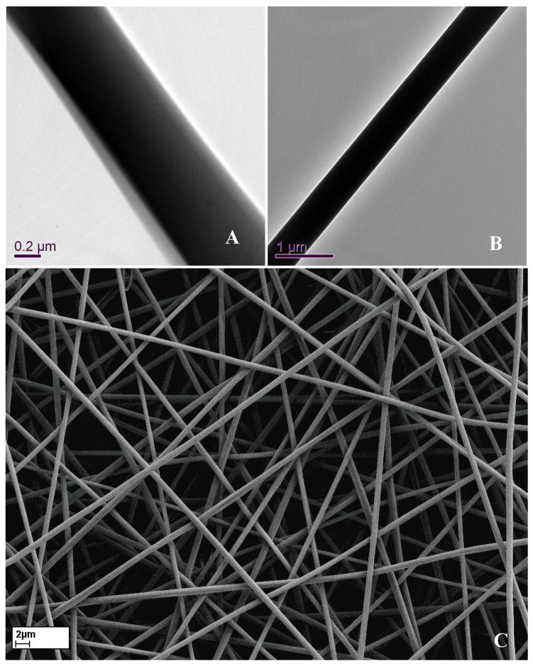
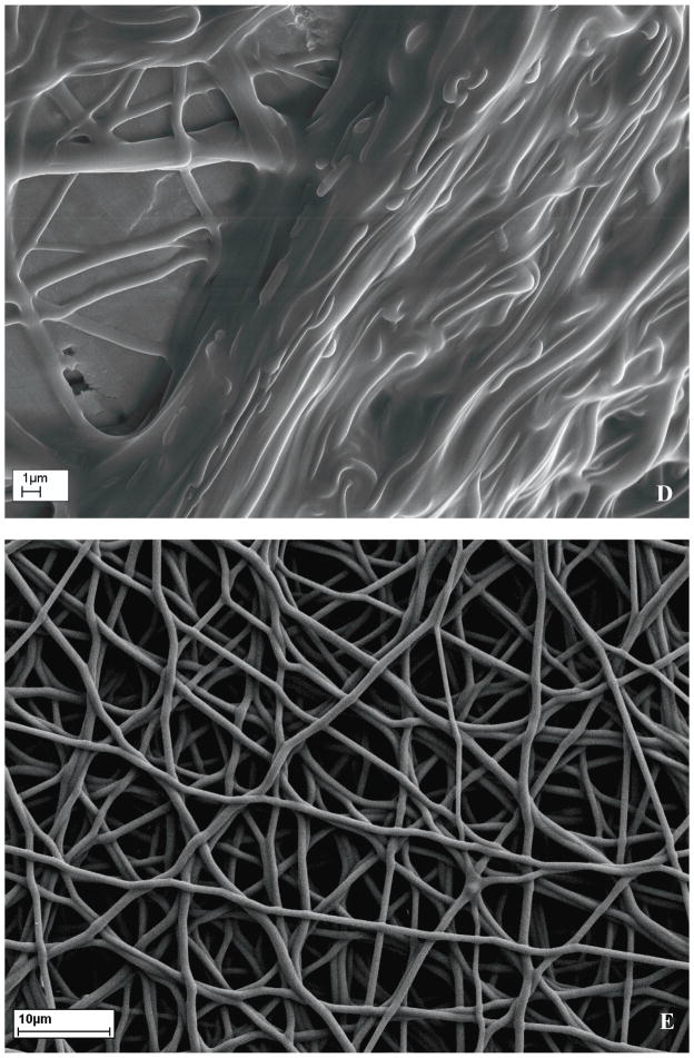
The formation of the co-axial fibre structure was first ascertained using TEM as illustrated in Fig 1A. Compared with as-electrospun PU fibre (Fig 1B), distinctly different contrast between the core and skin generated along the fibre long axis demonstrated a core-shell structure of the co-axial fibre, which was attributed to different electron absorption of semicrystalline PU and amorphous gelatin materials and their interaction with electrons. Thereafter, to make gelatin insoluble and maintain the co-axial fibre structure (Fig 1C), it was crosslinked with glutaraldehyde using two methods. Firstly, freshly electrospun co-axial fibre membranes were immersed in glutaraldehyde solution, which disrupted the co-axial fibre structure (Fig 1D). Secondly, the membranes were incubated in a glutaraldehyde saturated air for 3 days, which preserved the co-axial fibre structure while making the gelatin sheath insoluble in water (Fig 1E). Similar result was also reported earlier [20]. Four co-axial fibre compositions, designated as 2PU10GE, 4PU10GE, 6PU10GE and 8PU10GE were further characterised in this study.
Figure 1.
Morphology of electrospun membranes as seen under TEM (A & B) and SEM (C to E). A) As-spun co-axial fibre showing PU-core and gelatin-Shell, B) As-spun PU fibre, C) discreet as-spun fibres, D) membranes crosslinked by immersion in glutaraldehyde solution showing disruption of fibro-porous structure, and E) membranes crosslinked using glutaraldehyde vapour that maintained their fibro-porous structure, but with fibres crosslinked with neighbouring fibres at contact points.
To further prove the formation of core-shell fibre structure and any interactions between gelatin and PU at their interface, ATR-FTIR spectra (Fig S1A) were recorded for the different coaxial fibres without crosslinking the gelatin shell, while having their feed components – gelatin powder and PU pellets as controls. The gelatin showed its typical amide bands at 1634 cm−1 (amide I), 1531 cm−1 (amide II) and 1233 cm−1 (amide III) corresponding to C=O stretching, the coupling of N–H bending and C–N stretching vibrations, and N-H bending respectively pertaining to the triple helical structure of gelatin [21]. The typical PU peaks included the C-H stretching vibrations between 2825 and 2946 cm−1, 1731 cm−1 the free urethane carbonyl peak, 1106 cm−1 the soft segment ether peak and 1033 cm−1 the hard segment ether peak. The spectra for co-axial fibres showed the unique peaks of both PU and gelatin indicating the presence of both PU and gelatin in the co-axial fibre membranes. The broad absorption band centred at ~3288 cm−1 was found in the FTIR spectra of all PU/gelatin coaxial fibres, which can be attributed to overlapping peaks of the N-H and O-H stretching vibration. Moreover, no shift in characteristic peaks of either PU or gelatin was observed for any of the electrospun coaxial fibre membranes, suggesting that there may be no obvious interaction between PU and gelatin. This is consistent with the observation on electrospun gelatin/PU blended nano-fibres reported earlier [22].
FTIR spectra were also recorded for co-axial fibre membranes from which the gelatin shell was washed off using DI water at 40 °C for 1 week with water changes every 24 h. The spectra for all membranes were similar to that of pure PU, with the exception of 2PU10GE samples, which showed a prominent peak, at about 1633 cm−1 unique to pure gelatin (Fig S1B), indicating a trace of gelatin remained. Moreover, the morphology of 2PU10GE showed spreading of the polymer between the fibres (Fig S1C-F). Although, not spreading out as observed with 2PU10GE, the fibres of the other membranes appeared to fuse with neighbouring fibres. When the GE was washed off, the residual PU fibre was envisaged to collapse and pack densely, resulting in many fibrils and bundles, especially in the case of 2PU10GE, the diameter of PU core fibres was so thin (see Section 3.3) that their packing became much denser, which could trap a trace of gelatin left within the PU mesh.
To visualise the core-shell structure of the co-axial fibres under SEM, following crosslinking of gelatin-shell with glutaraldehyde vapour, the PU core was dissolved using THF. The resulting hollow fibres for the different membranes are shown in Fig S2. The tubular structure was prominent for all membranes. However, for 4PU10GE membranes some of the fibres did not form complete tubes (gelatin-shell) (Fig S2B), which could be due to an observed experimental anomaly, wherein the fast evaporation of solvent causes solidification of gelatin on the tip of the nozzle either blocking or significantly slowing the shell fluid flow. The amount of the shell liquid in Taylor cone thus decreases to a point where the viscous drag applied by the sheath solution could be insufficient to confine the core solution within the Taylor cone. We observed that the evaporation of the solvent (TFE) could be slowed to ensure formation of proper coaxial fibre by saturating the air around the spinneret with the solvent or by increasing ambient humidity.
3.3. Morphology and dimensions of coaxial fibres
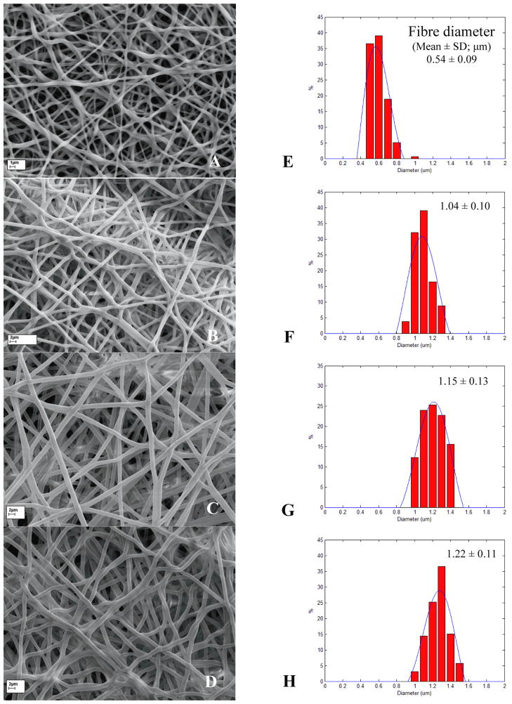
The morphology and fibre diameter distributions for 2PU10GE, 4PU10GE, 6PU10GE and 8PU10GE are presented in Fig. 2. For the 2PU10GE membranes occasional spindle shaped beads formed (Fig 2A), which could be due to the disparity in solvent content in the core PU solution compared to the shell gelatin solution. Due to the low viscosity of the core PU solution (~332.76 × 10⁻⁴ pa/s, Table S1), droplets could form while the polymer solution accelerated to the collector resulting in bead formation, similar to that reported earlier [23]. For 4PU10GE, 6PU10GE and 8PU10GE, the viscosity of core PU solution (Table S1) was sufficient to result in seamless coaxial fibres without beads (Fig 2B to D). Further, their narrow fibre diameter distributions indicated a stable electrospinning process (Fig 2E to H). The average fibre diameter increased significantly with increasing feed solution concentration of the core PU solution, which phenomenon is widely reported [24–26]. Fibre diameters were submicron only for 2PU10GE membranes.
Figure 2.
SEM images (A to D) and fibre diameter distribution histograms (E to H) for the different crosslinked co-axial fibre membranes 2PU10GE (A & E), 4PU10GE (B & F), 6PU10GE (C & G) and 8PU10GE (D & H) respectively. Average fibre diameters for each membrane were significantly different from all other membranes (p<0.05).
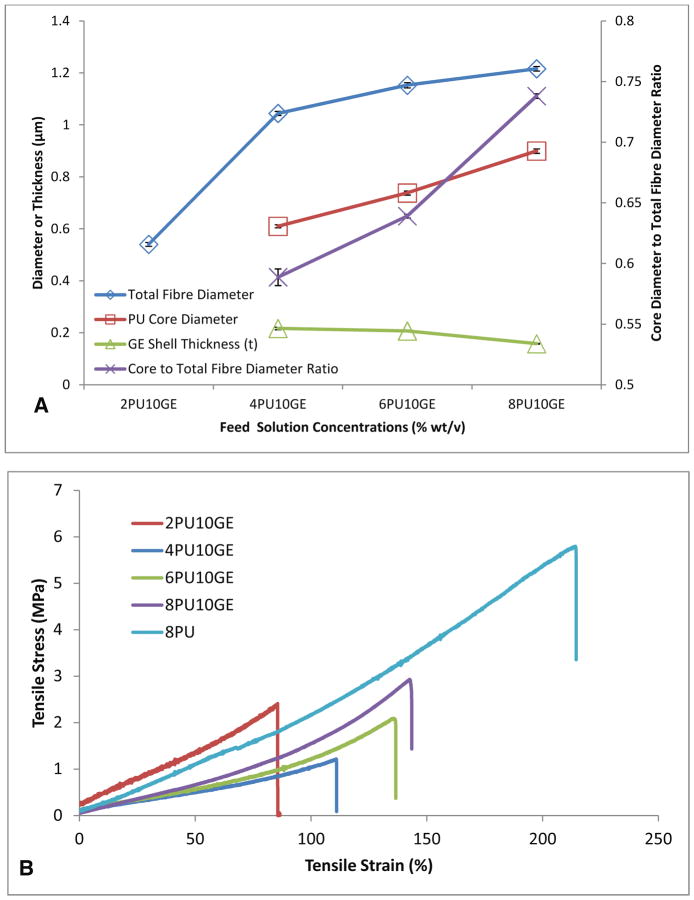
The diameter of PU-core was measured on SEM images (Fig S1C-F) of co-axial membranes whose gelatin-shells were washed off and subtracted from that of the co-axial fibres with glutaraldehye crosslinked gelatin-shells (Fig 2) to obtain the total thickness gelatin-Shell. The results are presented in Fig 3. The data for 2PU10GE could not be obtained because the thin PU fibres failed to retain their integrity as well as the presence of residual gelatin (Fig S1B). However, for the rest of the membranes that had intact fibres, the increase in concentration of feed PU solution significantly increased the diameter of the PU-core in the coaxial fibre, while the thickness of its gelatin-shell (t, radial) showed a gradual decrease (Fig 3A). The ratio of the diameter of PU core to the total thickness of gelatin shell on the co-axial fibres further reiterates the increasing volume of PU core with increasing feed PU solution concentration. Similar increase in the diameter of PCL-core with a parallel decrease in gelatin-shell thickness was also reported by Zhang et al., who explained the decrease in the shell thickness to be due to the same mass of the shell layer distributed over a larger core [27].
Figure 3.
A) Co-axial fibre dimensions (±SE, n=160) and B) Typical stress-strain curves based on uniaxial tensile tests (n=4) of coaxial fibres electrospun on a flat plate collector as a function of increasing PU (core) feed solution concentrations (% wt/v), while maintaining the gelatin (shell) feed solution concentration. 8PU membranes were used as controls for mechanical testing.
3.4. Tensile mechanical properties of electrospun coaxial fibre membranes
The tensile mechanical properties of water swollen electrospun coaxial fibre membranes are summarised in Table 2 and Fig 3B. Electrospun pure PU fibre (8PU) and gelatin fibre [22] membranes are also listed as controls. 8PU membranes were highly flexible and elastic, while. On the other hand, gelatin fibre membranes was reported to be brittle and weak, especially when wet [22]. The co-axial fibre membranes showed intermediate tensile properties between that observed for 8PU and gelatin fibre membrane controls. Among the coaxial fibre membranes, the tensile properties improved with increasing core PU content (Table 2) with the exception of 2PU10GE, which had significantly higher Young’s modulus and lower strain at break. The higher elasticity of 2PU10GE membranes can be attributed to higher density of fibres per unit volume as well as higher degree of inter-fibre contacts and crosslinking. The lower strain at break for 2PU10GE can also be due to its larger content of crosslinked gelatin shall (~52 %). The other co-axial fibre membranes became more flexible with a significant increase of strain at breaks with increasing diameter of PU core. Similar results were also reported earlier [7, 28, 29]. Furthermore, the failure of coaxial fibres, containing gelatin shell, under tensile load is said to first start with cracks in the hydrated gelatin, which is then translated to the core [4, 22, 28]. This presumption was verified by Zhao et al. [30] using SEM showing the cross section of crosslinked gelatin coated PCL fibres after fracture. Therefore, the mechanical properties of the co-axial fibrous membranes are resultant of the synergetic effect of core-shell structure.
Table 2.
Composition, dimension, porosity and mechanical properties of the membranes (wet).
| GE B [22] | 2PU10GE | 4PU10GE | 6PU10GE | 8PU10GE | 8PU [3] | |
|---|---|---|---|---|---|---|
| Mean fibre diameter (nm) | 496±62 | 541±91 | 1045±97 | 1153±129 | 1216±112 | 348± 87 |
| Mean Core (PU) diameter (nm) | - | - | 610±74 | 738± 97 | 900±107 | - |
| ~PU content (%) | 0 | 48.2 | 58.5 | 65.5 | 73.4 | 100 |
| Porosity (%) | - | - | 57.1±4.6 | 63.3±1.3 | 60.6±4.7 | 44.2±2.5 |
| Thickness (μm) | - | 37.8±3.4 | 44.2 ± 13.9 | 44.1±4.0 | 79.1 ± 7.4 | 45.0 ± 8.5 |
| Young’s Modulus 0–20% (MPa) | 1.4±0.1 | 2.25±0.6 | 0.90±0.05 | 0.93±0.14 | 1.22±0.17 | 2.3±0.9 |
| Ultimate Tensile Strength (MPa) | 0.6±0 | 1.92±0.6 | 1.49±0.24 | 1.83±0.21 | 2.16±0.46 | 5.8±2.1 |
| Strain at Break (%) | 78±50 | 81±35 | 125±10 | 133±7 | 136±17 | 191±61 |
3.5. Pore size and porosity
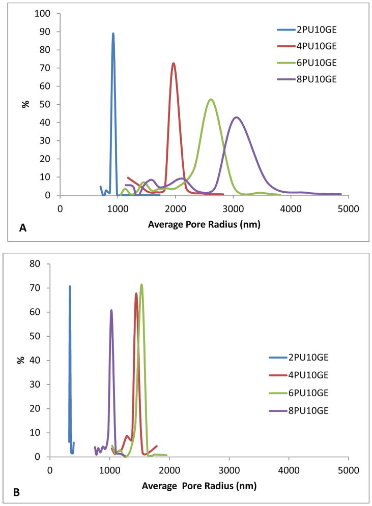
To study the effect of thickness on pore sizes, two electrospinning times, 10 and 40 min were chosen for spinning coaxial fibre membranes. The pore size distributions are presented in Fig. 4. For membranes electrospun for 10 minutes, an increasing pore size was observed with increasing fibre diameter (Fig. 4A), ranging from 920.70 nm for 2PU10GE-10′, 1964.34 nm for 4PU10GE-10′, 2624.23 nm for 6PU10GE-10′ through to 3051.74 nm for 8PU10GE-10′. Furthermore the pore size distribution was narrow and sharp for 2PU10GE-10′, which became broader for other coaxial fibre membranes with increasing fibre diameters (Fig. 4). The membranes having smaller fibre diameters have been widely reported to have smaller pore sizes and narrower pore size distribution [3, 31–33]. When the thickness of the coaxial fibre membranes was increased by increasing the electrospinning time to 40 min, the pore sizes again increased with increasing fibre diameter, with the exception of 8PU10GE membranes which had pore sizes smaller than 4PU10GE and 6PU10GE (Fig. 4B). However, compared to membranes electrospun for 10 min, all the thicker membranes showed smaller pore sizes: 333.9, 1444.3, 1535.6 and 1028.9 nm in radius respectively for 2PU10GE-40′, 4PU10GE-40′, 6PU10GE-40′ and 8PU10GE-40′ (Fig. 4B). Such influence of electrospinning duration on pore size was also observed by Chiu et al., who fabricated electrospun polyacrylonitrile ion-exchange membranes [34]. They reported a sharp decrease in average pore diameter in the first 1 to 3h electrospinning time following which the pore sizes stabilized. The decrease in pore sizes with increasing membrane thickness could be due to the tighter packing of fibres induced by the increasing weight of the fibres being continuously deposited. The notably lower porosity of the thickest 8PU10GE-40′ membranes (Fig. 4B) can also be attributed to the densely accumulated fibres leading to smaller pore sizes similar to that observed by Soliman et al. [33]. The denser fibre packing causing lower porosity is also supported by the gravimetry based porosity estimations (Table 3).
Figure 4.
Pore size distributions for the co-axial fibre membranes 2PU10GE, 4PU10GE, 6PU10GE and 8PU10GE electrospun for A) 10 and B) 40 min.
Table 3.
Porosity estimations for electrospun coaxial fibre membranes based on gravimetry, calculated using Eq. 2 and Eq. 3. n=3.
| Electrospun time, min | 2PU10GE | 4PU10GE | 6PU10GE | 8PU10GE | |
|---|---|---|---|---|---|
| Fibre Diameter (μm) | 0.54±0.06 | 1.04±0.10 | 1.15±0.13 | 1.22±0.11 | |
| Fibre Bulk density (g/cm3) | - | 1.34 | 1.34 | 1.32 | |
| Membrane Thickness (μm) | 10 | 21.6±4.0 | 23.4±2.6 | 25.1±5.2 | 22.2±14.0 |
| 40 | 56.8±4.9 | 40.3±5.7 | 36.0±5.4 | 67.7±6.7 | |
| Fibre packing density (g/cm3) | 10 | 0.285±0.068 | 0.276±0.009 | 0.257±0.066 | 0.214±0.079 |
| 40 | 0.595±0.045 | 0.539±0.057 | 0.474±0.017 | 0.469±0.056 | |
| Porosity (%) | 10 | - | 79.4 2±0.63 | 80.79±4.93 | 83.84±6.0 |
| 40 | - | 59.78±4.29 | 64.51±1.3 | 64.51±4.25 |
Membrane thickness, material bulk density, fibre packing density and pore volume estimations were calculated and summarised in Table 3 for the different electrospun coaxial fibre membranes electrospun for 10 and 40 min. As the core diameter in 2PU10GE could not be detected, its corresponding porosity was not calculated. No significant change in the overall thickness was observed when the coaxial fibre membranes (4PU10GE to 8PU10GE) were electrospun for 10 min. In addition, they had apparent densities (or fibre packing density) in the range of 0.21–0.28 g/cm3, which change was again not statistically significant, in spite of increasing feed PU solution concentration. Therefore, the comparable resultant pore volumes can primarily be ascribed to their corresponding similar bulk density of the composite PU-gelatin fibres (Table 3). All the coaxial fibre membranes electrospun for 10 min had pore-volumes greater than 60 %, which could be useful for tissue engineering application requiring cellular infiltration to the bulk of porous scaffolds [35].
However, when the electrospinning time was increased, inconsistent membrane thickness, fibre packing densities and pore volumes were observed (Table 3). The thickness of the membranes decrease from 2PU10GE to 6PU10GE, and that of 8PU10GE was higher than all the other membranes. The fibre packing densities also followed the trend observed with thickness measurements, but the fibre packing density for 8PU10GE was comparable to that observed for 6PU10GE. The pore volume estimations revealed a steady trend similar to that observed with membranes electrospun for 10 min. However, the pore volumes of coaxial fibre membranes electrospun for 40 min was significantly lower than those electrospun for 10 min. Overall, the insignificant variations in pore volumes with decreasing PU core volumes from 8PU10GE to 4PU10GE can be due to the cross-interference of the decreasing mechanical support in the inner layer and the cross-linking process. Although the porosity (pore volume) would decrease with the shrinking of gelatin shell due to glutaraldehyde crosslinking as demonstrated for hydrogels in general [30, 36–38], core PU with good mechanical properties can moderate the deformation during crosslinking process. Similar observation was also reported by Zhao et al., wherein crosslinking of gelatin shell layer resulted in negligible effects on porosity of coaxial fibre membranes having semi-crystalline hydrophobic PCL core [30]. To sum up, the pore sizes for PU-gelatin core-shell fibrous membranes are mainly dependent on fibre diameter, while the pore volume was dependent on both the fibre packing and the bulk densities. Electrospinning duration was shown to have a decreasing effect on pore sizes and volume for the electrospinning times tested in this study.
3.6. Contact angle
Addition of hydrophilic gelatin to the co-axial fibre structure was expected to increase the hydrophilicity of the electrospun membranes. The surface hydrophilicity for the coaxial fibres was so quick that for 4PU10GE, 6PU10GE and 8PU10GE it was not possible to measure contact angles. 2PU10GE was the only coaxial fibre configuration for which contact angle could be measured (101°, Fig S3). The rapid wetting of coaxial fibres can be attributed both to hydrophilic surface chemistry and surface roughness [39, 40]. The smooth and essentially non-porous surfaces of glutaraldehyde crosslinked gelatin (Fig S3) and pure PU films had contact angles of 64° and 86° respectively [3]. Increasing surface roughness for the electrospun pure PU membranes showed increasing hydrophobicity that can be attributed to the hydrophobic air pockets in the pores [3]. In contrast, the increased roughness of co-axial fibre membranes made their surface highly hydrophilic, with an exception of 2PU10GE. For 2PU10GE a contact angle of 101° was observed, which was comparable to the pure PU fibre membranes (8PU, 104°) of similar submicron porosity. This may be reminiscent of “lotus effect” in that the intrinsic hydrophobicity of a surface can be enhanced by being textured with different length scale of roughness. The average pore radius of about 333 nm observed with 2PU10GE (Fig 4B), could be responsible for preventing the water droplet from wetting the nanostructured space between the nano-fibres. The macro-pores on the surface of 4PU10GE, 6PU10GE and 8PU10GE, could disrupt the integrity of water drop and thus, essentially accelerate its absorption into the macro pore network through capillary action.
3.7. Effective diffusion coefficient
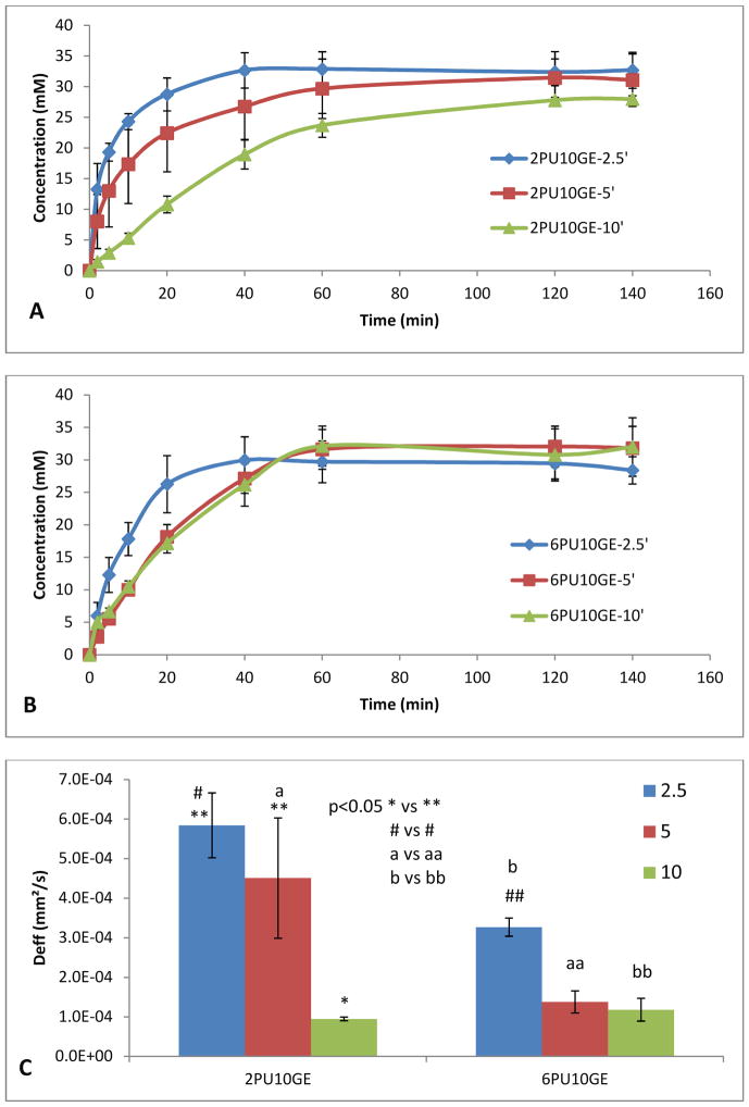
The permeability of the coaxial fibre membranes 2PU10GE and 6PU10GE of varying thicknesses to glucose was tested using biodialysers. The glucose diffusion followed an initial linear increase that plateaued off to a constant when the diffusion rate attained equilibrium (Fig 5A & B). The slope of the linear increase typically decreased with increasing membrane thickness, which was statistically significant for 2PU10GE-10′ membrane. The data was also fitted in Eq 5 to calculate relaxation times and effective diffusion constants for the membranes, which results are presented in Fig 5C and Table 4. The Deff for PU-gelatin coaxial fibre membranes ranged from 9.5±0.47 × 10⁻⁵ to 5.84±0.44 × 10⁻⁴ mm2/s, which in general were higher compared to that we reported for pure PU fibre membranes (0.429±0.45 × 10⁻⁵ to 4.88±0.44 × 10⁻⁴ mm2/s) depending on their fibre composition and thickness [3]. The comparatively higher flux rates for PU-gelatin fibres can be attributed to the higher pore volumes (about 78 to 82 %, Table 3) and the hydrophilic gelatin surface of the co-axial fibres, which was maximum for 2PU10GE-2.5′ membranes, even closer to that of glucose in water 6.73 × 10⁻⁴ mm2/s [41]. However, with increasing membrane thickness a decrease in Deff with a concomitant increase in average relaxation time (τ) was observed (Fig. 5C and Table 4) consistent with that observed with pure PU fibre membranes [3].
Figure 5.
Glucose diffusion across A) 2PU10GE and B) 6PU10GE membranes as a function of time, and thickness (electrospinning times of 2.5, 5 and 10 min), (C) the trends of the effective diffusion coefficient calculated from the diffusion measurement as a function of time, and thickness (electrospinning times of 2.5, 5 and 10 min). Data is represented as Mean ± SE of mean, n=5.
Table 4.
The thickness of electrospun membranes used for diffusion tests and their corresponding average relaxation time, τ, and effective diffusion coefficient (Deff) as a function of electrospinning time. n=5, p<0.05 between * and **. (n=5)
| Sample | Mean of Thickness (μm) | mean relaxation time, τ (min) | Effective diffusion coefficient, Deff (mm2/s) | |
|---|---|---|---|---|
| 2PU10GE | 2PU10GE-2.5′ | 18.0 | 5.08±0.67 | 5.84±0.82 × 10⁻⁴ |
| 2PU10GE-5′ | 20.5 | 7.92±2.27 | 4.51±1.52 × 10⁻⁴ | |
| 2PU10GE-10′ | 25.6 | 43.99±2.22 | 9.5±0.47 × 10⁻⁵ | |
| 6PU10GE | 6PU10GE-2.5′ | 16.0 | 8.01±0.54 | 3.27±0.23 × 10⁻⁴ |
| 6PU10GE-5′ | 17.4 | 21.10±3.85 | 1.38±0.28 × 10⁻⁴ | |
| 6PU10GE-10′ | 20.2 | 29.24±8.39 | 1.18±0.29 × 10⁻⁴ | |
3.8. Efficacy of electrospun coaxial fibre membranes as coatings for implantable coil-type glucose biosensors
Among 4PU10GE, 6PU10GE and 8PU10GE, the variation in fibre diameters was narrow ranging from 1.04 to 1.22 μm (Table 2). Coaxial fibre structure was not consistent for 4PU10GE, while the pore sizes distribution for 8PU10GE was broader than both 4PU10GE and 6PU10GE (Fig. 4A). Hence, the 6PU10GE membrane, having consistent coaxial fibre structure and pore size, was chosen as coating for glucose biosensors. However, for studying the effects of fibre diameter of coaxial fibre membranes on sensor function, 2PU10GE membrane that has about half the average fibre diameter observed for 6PU10GE, was also chosen. Effectively, the effects of coaxial fibre membranes on glucose biosensor function were evaluated as a function of fibre diameter and gelatin content. 2PU10GE membrane had an average fibre diameter of 540.61±90.83 and ~51.8% gelatin while that for 6PU10GE was 1152.93±128.77 and ~34.5% respectively. The two types of membranes were electrospun directly on glucose biosensors using the dynamic collector, wherein the biosensor was rotated at about 660 to 690 rpm in the electrospinning field.
Each of the coaxial fibre membranes, were tested on sensors with (Pt-GOD-EPU) and without (Pt-GOD) EPU mass-transport limiting membrane. The results were compared with that of Pt-GOD and Pt-GOD-EPU sensors. The sensor function was tested at regular intervals starting one week before applying coatings, to 84 days (12 weeks) after coating. The sensitivity and linearity results at each tested time point were normalized to that at day 7, before applying coatings.
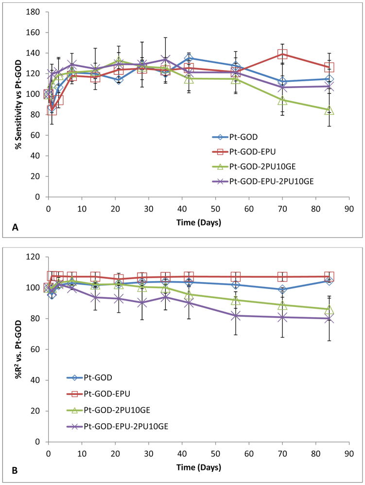
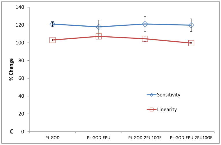
The effect of 2PU10GE coatings on glucose biosensor function is illustrated in Fig. 6. The sensitivity profiles for all sensors before and after coating with membranes were similar to that shown by Pt-GOD sensors indicating no obvious effects of either EPU or 2PU10GE membranes on sensor sensitivity (Fig 6A). However, the linearity (R2) for the detection range of 2 to 30 mM glucose was only improved for EPU membrane, indicating that the 2PU10GE membranes did not function as a durable mass transport limiting membrane over the period of time tested (Fig 6B). Thus, as summarised in Fig 6C, 2PU10GE did not affect sensor sensitivity, but also did not function as a mass-transport limiting membrane.
Figure 6.
Effect of electrospun 2PU10GE coaxial fibre membranes on the in vitro function coil-type implantable glucose biosensor: % change in A) sensitivity and B) linearity normalised to that at day 7 before applying coating(s) as a function of time; and C) % change in sensitivity and linearity plotted as a function of sensor coating configurations.
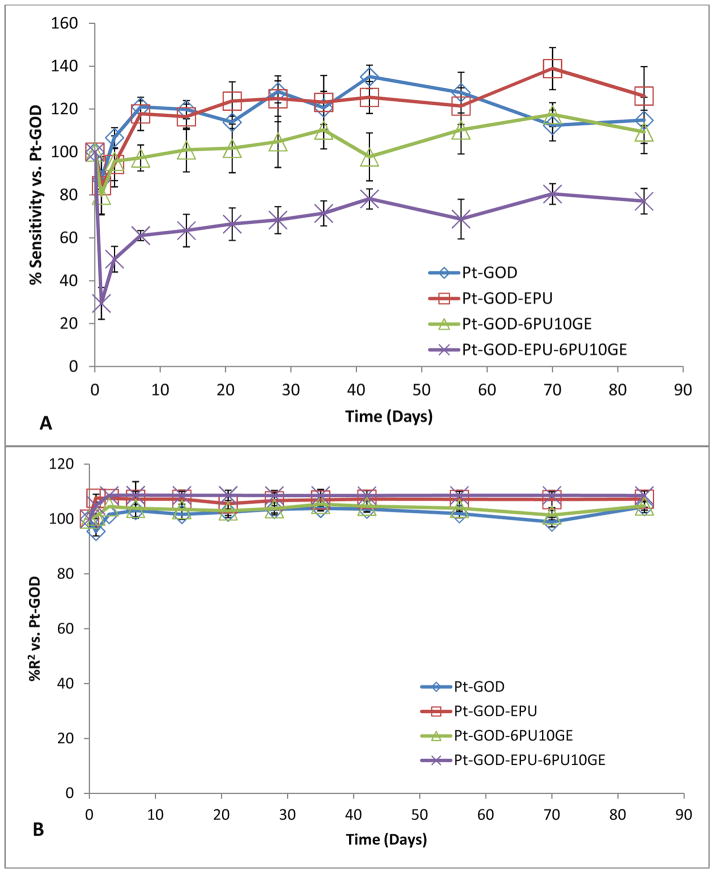
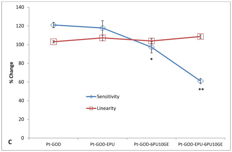
Different from 2PU10GE coatings, 6PU10GE caused a reduction in sensor sensitivity, but extended the linear detection range for glucose biosensors (Fig 7). The sensitivity profiles for sensors coated with 6PU10GE were significantly lower than that of Pt-GOD and Pt-GOD-EPU sensors (Fig 7A). However, both EPU and 6PU10GE membranes extended the linear detection range for Pt-GOD to cover the physiologically relevant detection range of 2 to 30 mM glucose, demonstrating that 6PU10GE membranes function as a mass transport limiting membrane (Fig 7B). The trends in % change in sensitivity and linearity as a function of sensor coating composition further reiterate the above observations (Fig 7C).
Figure 7.
Effect of electrospun 6PU10GE coaxial fibre membranes on the in vitro function coil-type implantable glucose biosensor: A & B) % change in sensitivity and linearity normalised to that at day 7 before applying coating(s) as a function of time; and C) the % change in sensitivity and linearity plotted as a function of sensor coating configurations. Each of * and ** indicate statistical difference from all other groups.
3.9. Long-term stability of sensor function for glucose biosensors coated with coaxial fibre membranes
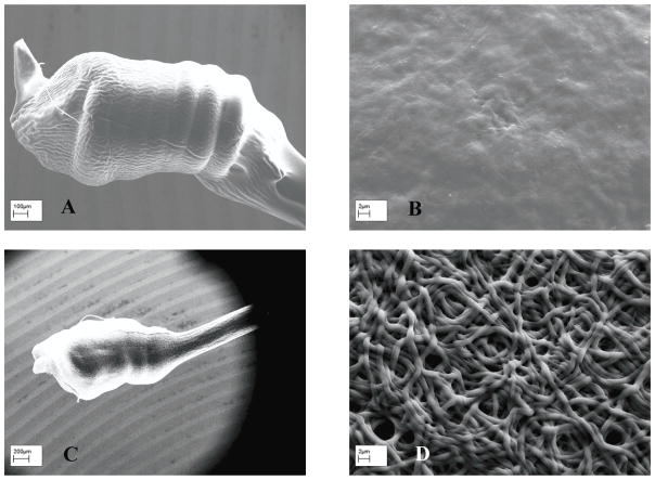
The sensitivity of sensors coated with both 2PU10GE and 6PU10GE were stable throughout the study for 12 weeks. However, a decrease in linearity for 2PU10GE coated Pt-GOD and Pt-GOD-EPU sensors was observed. To identify the cause for this undesirable decrease in linearity, the morphology of the sensors after completion of the study was assessed under SEM. As shown in Fig. 8A&B, the integrity of the fibro-porous membrane structure was disrupted for 2PU10GE forming a PU fibre-reinforced gelatin composite film. On the other hand, the fibro-porous structure of 6PU10GE membranes was more or less intact even after 12 weeks of immersion in PBS pH 7.4 at 37°C although neighbouring fibres fused (Fig 8C&D).
Figure 8.
The morphology of coaxial fibre membranes after 12 weeks of immersion in PBS (pH 7.4) and intermittent sensor function tests of 2PU10GE (A & B) and 6PU10GE (C & D).
4. Conclusions
The solvent, solution concentration and process parameters for electrospinning PU-core and gelatin-shell coaxial fibre membranes were optimized. PU-GE coaxial fibres of varying composition and structure were prepared and characterized. With increasing PU feed solution concentration, an increase in the diameter of PU core, with concomitant reduction in gelatin shell thickness was demonstrated. Accordingly, the fibres also inherited intermediate mechanical properties of their constituents - PU and gelatin. The higher the gelatin-shell content the more brittle, while the higher the PU-core content the higher was the strength and the elongation at break for the coaxial fibre membranes. The gelatin-shell ensured higher hydrophilicity and flux-rates for glucose transport across the PU-gelatin coaxial fibre membranes. The effects of the coaxial fibre membranes on in vitro function of electrochemical glucose biosensors were also evaluated. Higher gelatin content in the coaxial fibre resulted in maintenance of sensitivity similar to that of control sensor without the coaxial fibre coating, but failed to function as a mass transport limiting membrane and also lost the integrity of its fibro-porous structure. In contrast, a thinner gelatin-shell layer on PU-core resulted in lowered sensitivity, but the coaxial membrane functioned as a mass-transport limiting membrane, while maintaining the integrity of its fibro-porous structure till the end of the study period of 12 weeks. Thus, the electrospun PU-gelatin coaxial-fibre membranes having significantly high pore volumes, interconnected porosities and tailorable mechanical properties, permeability and surface chemistry compared to conventional solvent cast membranes can find applications as tissue engineering coatings for biosensors requiring analyte exchange and other implantable biomedical devices. Such biomimetic coatings are anticipated to play an important role in engineering tissue responses to the implanted biosensors, which pre-clinical functional efficacy studies will be reported in our next paper.
Supplementary Material
Table S1. Dynamic viscosity of the different PU and gelatin solutions used for electrospinning co-axial fibre membranes, * viscosity was higher than measuring limit for the instrument.
Figure S1. FTIR spectra (A & B) and SEM images (C to F) of electrospun co-axial fibre membranes with non-crosslinked gelatin shell (A) and with gelatin shell washed off (B to F). Morphology: C) 2PU10GE, D) 4PU10GE, E) 6PU10GE and F) 8PU10GE.
Figure S2. SEM images showing the hollow fibres (with PU core removed by dissolving in THF) for A) 2PU10GE, B) 4PU10GE, C) 6PU10GE and D) 8PU10GE electrospun co-axial fibre membranes.
Figure S3. The contact angle for A) glutaraldehyde crosslinked gelatin film and B) 2PU10GE coaxial fibre membrane. The surface wetting for 4PU10GE, 6PU10GE and 8PU10GE membranes was too quick to take any contact angle measurements.
Acknowledgments
This research is supported by Brunel University, the Royal Society research grant (RG100129), the Royal Society-NSFC international joint project grant (JP101064) and the National Institute of Health (NIH/NIBIB, grant R01EB001640).
References
- 1.Wisniewski N, Moussy F, Reichert WM. Characterization of implantable biosensor membrane biofouling. Fresenius J Anal Chem. 2000;366:611–621. doi: 10.1007/s002160051556. [DOI] [PubMed] [Google Scholar]
- 2.Wang N, Burugapalli K, Song W, Halls J, Moussy F, Ray A, Zheng Y. Electrospun Fibro-porous Polyurethane Coatings for Implantable Glucose Biosensors. Biomaterials. 2013;34:888–901. doi: 10.1016/j.biomaterials.2012.10.049. [DOI] [PMC free article] [PubMed] [Google Scholar]
- 3.Wang N, Burugapalli K, Song W, Halls J, Moussy F, Zheng Y, Ma Y, Wu Z, Li K. Tailored fibro-porous structure of electrospun polyurethane membranes, their size-dependent properties and trans-membrane glucose diffusion. J Membr Sci. 2013;427:207–217. doi: 10.1016/j.memsci.2012.09.052. [DOI] [PMC free article] [PubMed] [Google Scholar]
- 4.Han D, Boyce ST, Steckl AJ. Versatile core-sheath biofibers using coaxial electrospinning. Mater Res Soc Symp Proc. 2008;1094:33–38. [Google Scholar]
- 5.Zhang Y, Ouyang H, Lim CT, Ramakrishna S, Huang Z-M. Electrospinning of gelatin fibers and gelatin/PCL composite fibrous scaffolds. J Biomed Mater Res. 2005;72B:156–165. doi: 10.1002/jbm.b.30128. [DOI] [PubMed] [Google Scholar]
- 6.Wu L, Li H, Li S, Li X, Yuan X, Li X, Zhang Y. Composite fibrous membranes of PLGA and chitosan prepared by coelectrospinning and coaxial electrospinning. J Biomed Mater Res. 2010;92A:563–574. doi: 10.1002/jbm.a.32393. [DOI] [PubMed] [Google Scholar]
- 7.Chen R, Huang C, Ke Q, He C, Wang H, Mo X. Preparation and characterization of coaxial electrospun thermoplastic polyurethane/collagen compound nanofibers for tissue engineering applications. Colloid Surf B: Biointerfaces. 2010;79:315–325. doi: 10.1016/j.colsurfb.2010.03.043. [DOI] [PubMed] [Google Scholar]
- 8.Trzebinski J, Moniz AR-B, Sharma S, Burugapalli K, Moussy F, Cass AEG. Hydrogel membrane improves batch-to-batch reproducibility of an enzymatic glucose biosensor. Electroanalysis. 2011;23:2789–2795. [Google Scholar]
- 9.Yu B, Long N, Moussy Y, Moussy F. A long-term flexible minimally-invasive implantable glucose biosensor based on an epoxy-enhanced polyurethane membrane. Biosens Bioelectron. 2006;21:2275–2282. doi: 10.1016/j.bios.2005.11.002. [DOI] [PubMed] [Google Scholar]
- 10.Yu B, Moussy Y, Moussy F. Coil-type implantable glucose biosensor with excess enzyme loading. Front Biosci. 2005;10:512–520. doi: 10.2741/1547. [DOI] [PubMed] [Google Scholar]
- 11.Gopal R, Kaur S, Ma Z, Chan C, Ramakrishna S, Matsuura T. Electrospun nanofibrous filtration membrane. J Membr Sci. 2006;281:581–586. [Google Scholar]
- 12.Mwangi JW, Ofner CM., Iii Crosslinked gelatin matrices: release of a random coil macromolecular solute. Int J Pharm. 2004;278:319–327. doi: 10.1016/j.ijpharm.2004.03.024. [DOI] [PubMed] [Google Scholar]
- 13.Huang Z-M, Zhang YZ, Ramakrishna S, Lim CT. Electrospinning and mechanical characterization of gelatin nanofibers. Polymer. 2004;45:5361–5368. [Google Scholar]
- 14.Korsmeyer RW, Gurny R, Doelker E, Buri P, Peppas NA. Mechanisms of solute release from porous hydrophilic polymers. Int J Pharm. 1983;15:25–35. doi: 10.1002/jps.2600721021. [DOI] [PubMed] [Google Scholar]
- 15.Leoni L, Boiarski A, Desai TA. Characterization of Nanoporous Membranes for Immunoisolation: Diffusion Properties and Tissue Effects. Biomed Microdev. 2002;4:131–139. [Google Scholar]
- 16.Sharkawy AA, Klitzman B, Truskey GA, Reichert WM. Engineering the tissue which encapsulates subcutaneous implants. I. Diffusion properties. J Biomed Mater Res. 1997;37A:401–412. doi: 10.1002/(sici)1097-4636(19971205)37:3<401::aid-jbm11>3.0.co;2-e. [DOI] [PubMed] [Google Scholar]
- 17.Boss C, Meurville E, Sallese J-M, Ryser P. Size-selective diffusion in nanoporous alumina membranes for a glucose affinity sensor. J Membr Sci. 2012;401–402:217–221. [Google Scholar]
- 18.Van Os PJHJ, Bult A, Van Bennekom WP. A glucose sensor, interference free for ascorbic acid. Anal Chim Acta. 1995;305:18–25. [Google Scholar]
- 19.Uang Y-M, Chou T-C. Fabrication of glucose oxidase/polypyrrole biosensor by galvanostatic method in various pH aqueous solutions. Biosens Bioelectron. 2003;19:141–147. doi: 10.1016/s0956-5663(03)00168-4. [DOI] [PubMed] [Google Scholar]
- 20.Zhao J, Zhao Y, Guan Q, Tang G, Zhao Y, Yuan X, Yao K. Crosslinking of electrospun fibrous gelatin scaffolds for apatite mineralization. J Appl Polym Sci. 2011;119:786–793. [Google Scholar]
- 21.Chang MC, Ko CC, Douglas WH. Conformational change of hydroxyapatite/gelatin nanocomposite by glutaraldehyde. Biomaterials. 2003;24:3087–3094. doi: 10.1016/s0142-9612(03)00150-9. [DOI] [PubMed] [Google Scholar]
- 22.Kim SE, Heo DN, Lee JB, Kim JR, Park SH, Jeon SH, Kwon IK. Electrospun gelatin/polyurethane blended nanofibers for wound healing. Biomed Mater. 2009;4:044106. doi: 10.1088/1748-6041/4/4/044106. [DOI] [PubMed] [Google Scholar]
- 23.Diaz E, Fernandez-Nieves A, Barrero A, Marquez M, Loscertales G. Fabrication of structured micro and nanofibers by coaxial electrospinning. J Phys Confer Series. 2008:127. [Google Scholar]
- 24.Huang ZM, Zhang YZ, Kotaki M, Ramakrishna S. A review on polymer nanofibers by electrospinning and their applications in nanocomposites. Comp Sci Technol. 2003;63:2223–2253. [Google Scholar]
- 25.Yu JH, Fridrikh SV, Rutledge GC. Production of Submicrometer Diameter Fibers by Two-Fluid Electrospinning. Adv Mater. 2004;16:1562–1566. [Google Scholar]
- 26.Huang ZM, Zhang Y, Ramakrishna S. Double-layered composite nanofibers and their mechanical performance. J Polym Sci B Polym Phys. 2005;43:2852–2861. [Google Scholar]
- 27.Zhang Y, Huang Z-M, Xu X, Lim CT, Ramakrishna S. Preparation of core-shell structured PCL-r-gelatin bi-component nanofibers by coaxial electrospinning. Chem Mater. 2004;16:3406–3409. [Google Scholar]
- 28.Lu Y, Jiang H, Tu K, Wang L. Mild immobilization of diverse macromolecular bioactive agents onto multifunctional fibrous membranes prepared by coaxial electrospinning. Acta Biomaterialia. 2009;5:1562–1574. doi: 10.1016/j.actbio.2009.01.044. [DOI] [PubMed] [Google Scholar]
- 29.Heydarkhan-Hagvall S, Schenke-Layland K, Dhanasopon AP, Rofail F, Smith H, Wu BM, Shemin R, Beygui RE, MacLellan WR. Three-dimensional electrospun ECM-based hybrid scaffolds for cardiovascular tissue engineering. Biomaterials. 2008;29:2907–2914. doi: 10.1016/j.biomaterials.2008.03.034. [DOI] [PMC free article] [PubMed] [Google Scholar]
- 30.Zhao P, Jiang H, Pan H, Zhu K, Chen W. Biodegradable fibrous scaffolds composed of gelatin coated poly(ε-caprolactone) prepared by coaxial electrospinning. J Biomed Mater Res. 2007;83A:372–382. doi: 10.1002/jbm.a.31242. [DOI] [PubMed] [Google Scholar]
- 31.Hartman O, Zhang C, Adams EL, Farach-Carson MC, Petrelli NJ, Chase BD, Rabolt JF. Microfabricated Electrospun Collagen Membranes for 3-D Cancer Models and Drug Screening Applications. Biomacromolecules. 2009;10:2019–2032. doi: 10.1021/bm8012764. [DOI] [PMC free article] [PubMed] [Google Scholar]
- 32.Dotti F, Varesano A, Montarsolo A, Aluigi A, Tonin C, Mazzuchetti G. Electrospun porous mats for high efficiency filtration. J Indust Textiles. 2007;37:151–162. [Google Scholar]
- 33.Soliman S, Sant S, Nichol JW, Khabiry M, Traversa E, Khademhosseini A. Controlling the porosity of fibrous scaffolds by modulating the fiber diameter and packing density. J Biomed Mater Res. 2011;96A:566–574. doi: 10.1002/jbm.a.33010. [DOI] [PubMed] [Google Scholar]
- 34.Chiu HT, Lin JM, Cheng TH, Chou SY. Fabrication of electrospun polyacrylonitrile ion-exchange membranes for application in lysozyme. Expr Polym Lett. 2011;5:308–317. [Google Scholar]
- 35.Chong EJ, Phan TT, Lim IJ, Zhang YZ, Bay BH, Ramakrishna S, Lim CT. Evaluation of electrospun PCL/gelatin nanofibrous scaffold for wound healing and layered dermal reconstitution. Acta Biomaterialia. 2007;3:321–330. doi: 10.1016/j.actbio.2007.01.002. [DOI] [PubMed] [Google Scholar]
- 36.Wang X, Um IC, Fang D, Okamoto A, Hsiao BS, Chu B. Formation of water-resistant hyaluronic acid nanofibers by blowing-assisted electro-spinning and non-toxic post treatments. Polymer. 2005;46:4853–4867. [Google Scholar]
- 37.Yao L, Haas TW, Guiseppi-Elie A, Bowlin GL, Simpson DG, Wnek GE. Electrospinning and stabilization of fully hydrolyzed poly(vinyl alcohol) fibers. Chem Mater. 2003;15:1860–1864. [Google Scholar]
- 38.Jin X, Hsieh Y-L. pH-responsive swelling behavior of poly(vinyl alcohol)/poly(acrylic acid) bi-component fibrous hydrogel membranes. Polymer. 2005;46:5149–5160. [Google Scholar]
- 39.Acatay K, Simsek E, Ow-Yang C, Menceloglu YZ. Tunable, superhydrophobically stable polymeric surfaces by electrospinning. Angew Chem Int Ed Engl. 2004;43:5210–5213. doi: 10.1002/anie.200461092. [DOI] [PubMed] [Google Scholar]
- 40.Han D, Steckl AJ. Superhydrophobic and oleophobic fibers by coaxial electrospinning. Langmuir. 2009;25:9454–9462. doi: 10.1021/la900660v. [DOI] [PubMed] [Google Scholar]
- 41.Longsworth LG. Diffusion Measurements, at 25°, of Aqueous Solutions of Amino Acids, Peptides and Sugars. J Am Chem Soc. 1953;75:5705–5709. [Google Scholar]
Associated Data
This section collects any data citations, data availability statements, or supplementary materials included in this article.
Supplementary Materials
Table S1. Dynamic viscosity of the different PU and gelatin solutions used for electrospinning co-axial fibre membranes, * viscosity was higher than measuring limit for the instrument.
Figure S1. FTIR spectra (A & B) and SEM images (C to F) of electrospun co-axial fibre membranes with non-crosslinked gelatin shell (A) and with gelatin shell washed off (B to F). Morphology: C) 2PU10GE, D) 4PU10GE, E) 6PU10GE and F) 8PU10GE.
Figure S2. SEM images showing the hollow fibres (with PU core removed by dissolving in THF) for A) 2PU10GE, B) 4PU10GE, C) 6PU10GE and D) 8PU10GE electrospun co-axial fibre membranes.
Figure S3. The contact angle for A) glutaraldehyde crosslinked gelatin film and B) 2PU10GE coaxial fibre membrane. The surface wetting for 4PU10GE, 6PU10GE and 8PU10GE membranes was too quick to take any contact angle measurements.


