Abstract
Imaging three-dimensional structures represents a major challenge for conventional microscopies. Here we describe a Spatial Light Modulator (SLM) microscope that can simultaneously address and image multiple targets in three dimensions. A wavefront coding element and computational image processing enables extended depth-of-field imaging. High-resolution, multi-site three-dimensional targeting and sensing is demonstrated in both transparent and scattering media over a depth range of 300-1,000 microns.
OCIS codes: (110.1758) Computational imaging, (170.2655) Functional monitoring and imaging, (170.6900) Three-dimensional microscopy
1. Introduction
The natural world is fundamentally three dimensional. This simple fact has long presented difficulties for conventional high numerical aperture (NA) imaging systems, where the axial depth of focus scales as . Large NA systems are necessary in a variety of imaging and optical sensing applications, especially when signals are weak or spatially interspersed. The collection efficiency scales with , and the focal volume is proportional to . As a result, when using high NA optics to image volumes, it has been necessary to acquire data sequentially, which limits the speed of imaging and the ability to image multiple sites across the volume with true simultaneity. This is especially problematic when one wants to image in complex systems that exhibit distinct temporal dynamics at each point in space, such as imaging the activity of neurons in complete neural circuits - if possible simultaneously [1].
One possible solution for large aperture volume imaging is wavefront coding. This method has been well understood for more than a decade [2]. Wavefront coding introduces a known, strong optical aberration that dominates all other aberration terms, like defocus, over an extended Depth of Field (DOF). Under this imaging paradigm, the point-spread-function (PSF) is essentially invariant over a long distance, and straightforward computational tools can be used to recover image information over the entire extended DOF. The penalty for this extension is reduced peak signal intensity for objects in the nominal focal plane of the system – but with a much slower falloff in intensity with defocus than traditional imaging systems. Although wavefront coded, extended DOF systems have been successfully demonstrated, they have had limited penetration into the microscopy community. As applied to fluorescence microscopy, the principle limitations are that many real samples are complex structures with many axially overlapping features and can have a lack of inherent contrast without strong axial sectioning. These effects combine to yield raw images that are too muddled for effective disambiguation of objects, and the computational recovery of individual features becomes very difficult.
To overcome these problems, we take advantage of the optical flexibility of microscopy based on Spatial Light Modulation (SLM) [3] and demonstrate an optical system which can image fluorescence from multiple sites in three dimensions. This system consists of a wavefront coded imaging system coupled to a SLM-based illumination system. We use multi-photon excitation to generate a deterministic ensemble of spatially distinct signal sources and image all of these sites simultaneously. In this configuration, contrary to prior bright-field extended DOF techniques, any ambiguity arising from imaging unknown objects with extended axial features can now be fully accounted for with the a priori information imprinted on the system through the user defined SLM target locations.
This paper is arranged as follows. In Section 2, we review the use of engineered Point Spread Functions for Extended Depth-of-Field Imaging and discuss the relevance to our system. In Section 3, we review the use of Spatial Light Modulator (SLM) microscopes for specific and deterministic illumination of the sample. In Section 4, we introduce our joint experimental implementation of these two methods. In Section 5, we demonstrate 3D fluorescence imaging results in both transparent and scattering phantoms using this microscope. In Section 6, we discuss the implications of these results and identify areas for application-specific improvements of the method. In Section 7, we summarize these results and present our conclusions.
2. Extended depth-of-field imaging using engineered point spread functions
Conventional microscopes image a single plane and thus cannot accommodate three-dimensional microscopy without the use of mechanical movement to sequentially scan the volume [4–7]. Classically, this planar imaging condition is defined as having a DOF,
| (1) |
where only a single slice of this thickness can be sampled with high contrast in the object volume. If a single point-scanned illumination beam and single pixel detector modality is used (e.g. galvanometer or AOD scanned laser beam and photomultiplier tube) one can record from multiple sites and planes, but only serially. Sequential scanning of targets is still required, and despite sophisticated scanning systems, these systems cannot monitor multiple points with true simultaneity [8–11].
One technique that helps alleviate this limitation is to rely upon task-based approaches to imaging and leverage joint optical-digital design strategies that can be used to selectively enhance defocus-related performance through engineering of the optical Point Spread Function (PSF) [2,12–16]. For the particular case of extending the imaging DOF, the enhancement is gained by sacrificing the tightly-focused, symmetric spot traditionally chosen for optimal imaging of a single axial plane with high contrast, in favor of a highly aberrated PSF. By design, this aberrated PSF must overwhelm the aberrative effects of defocus over an extended axial range. After image acquisition, fast digital image restoration techniques (e.g. deconvolution) can be applied for estimating the original object free of these fixed optical aberrations. With such systems, the fall-off in intensity with defocus is much smaller and smoother than in a classical system thereby allowing multiple planes to be imaged simultaneously with similar fidelity. As a consequence, in properly engineered wavefront coding systems the nominally out-of-focus regions can now be imaged with higher SNR than traditionally available.
We selected the Cubic-phase (CP) mask from many known families of suitable engineered PSF designs because it is simple and well characterized. The mask modulates only the phase, not the amplitude (i.e. transparent), and can therefore maintain the full NA and photon-throughput of the imaging system, critical for photon starved applications, like fluorescence microscopy. It is also associated with an optical Modulation-Transfer-Function (MTF) which does not contain zeros allowing for a simple deconvolution to recover the original image [2]. The CP mask is implemented by placing a phase modulation of,
| (2) |
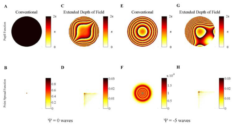
in the pupil plane of the imaging system, where u2, v2 are the normalized transverse coordinates of the imaging pupil plane and α is the coefficient that determines the trade-off of depth of field extension versus image contrast [2,17]. A simulated example demonstrating the defocus stability of the CP PSF relative to the conventional PSF is presented in Fig. 1 . Defocus is parameterized as,
| (3) |
in the paraxial approximation and assumes dz is much smaller than the lens focal length, f, where λ is the wavelength for the optical signal, NA is the numerical aperture of the objective, n is the refractive index in the object space and dz is the axial dislocation relative to the focal plane and the scalar value is the number of waves of defocus present at the edge of the microscope pupil.
Fig. 1.
Simulated pupil phase as a function of defocus for the conventional imaging microscope is shown in panels A (in focus), and E (out of focus) with the associated PSF in panels B (in focus) and F (out of focus), respectively. The pupil functions are color coded to represent the phase delay present at the pupil. The PSFs are color coded and scaled to be normalized to the in-focus conventional PSF. The representative pupil phase as a function of defocus for the extended DOF microscope is given in panels C (in focus) and G (out of focus) with the associated PSF in panels D and H, respectively. The cubic phase coefficient, α, is set to 5. The range of defocus shown in Media 1 (3.5MB, AVI) highlights the range of defocus values (|Ψ| < 10) where a dominant peak is qualitatively observed in the cubic phase PSF even though the side-lobe structure begins to break down, as seen in panel H at |Ψ| = 5 ( Media 1 (3.5MB, AVI) ).
For the purposes of this report, the localization of light into a clear dominant feature (i.e. the main/central lobe of the PSF) is critically important for both increasing the density of possible targets (if no signal post-processing is used) as well as providing a sufficient SNR for increased usable axial range. Therefore comparison in this study of the CP-PSF in this extended DOF system against a conventional microscope is frequently made on the basis of how efficiently each system localizes light relative to the in-focus PSF. The free variables when designing such a system are typically the maximum defocus to accommodate and the magnitude of the cubic-phase coefficient to use. The effect of defocus and cubic-phase modulation on the main lobe of the PSF is characterized in Fig. 2(A) . As α is increased, the size of the main lobe increases relative to the Airy disk found in conventional microscopes as shown in Fig. 2(B). However, as verified in Fig. 2(A) there is now a dramatic decrease in the spread of the signal as a function of defocus. A rule-of-thumb ratio can be provided from Fig. 2(A) where an extended DOF image can be acquired throughout a maximum defocus range of Ψ wave by using a cubic-phase coefficient of α ≈|Ψ|/2. The relative intensity of the CP-PSF compared to the performance of a conventional microscope shows a significant increase in the localization of signal at large defocus if sufficient α is applied, as shown in Fig. 2(C) – motivating our use of extended DOF techniques.
Fig. 2.
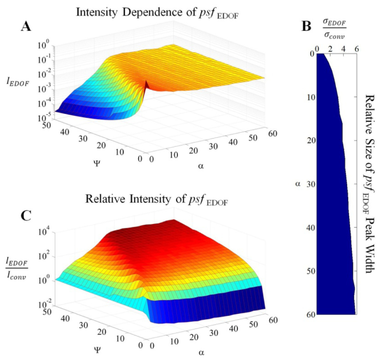
Simulated performance trade-offs of the Cubic-phase extended Depth of Field (EDOF) imaging system relative to the conventional microscope (abbreviated here as conv.). The relative intensity of the dominant peak in the PSF is mapped out as a function of both defocus (Ψ) and cubic-phase modulation (α) in Panel A showing that the cubic phase mask decreases attenuation with defocus. The relative width of the dominant lobe in the Cubic-phase PSF is shown in Panel B when compared with the in-focus conventional PSF, where σ is the width of a Gaussian fit to the PSF. The width of the dominant peak is shown to increase with a greater cubic-modulation coefficient. The relative intensity of the dominant lobe of the cubic-phase PSF compared with the conventional PSF with the same defocus is shown in Panel C. This shows that the uniformity of the cubic-phase PSF dominant lobe intensity indicated in Panel A will rapidly provide better out-of-focus signal localization when compared with the conventional imaging system.
3. Spatial Light Modulator microscopy for three-dimensional targeting
Spatial Light Modulator (SLM) microscopy is a method that allows for simultaneous dynamic illumination of multiple sites in the sample [3]. The illumination pattern can be tailored specifically to the particular sample, and could even be controlled via feedback from information present in the acquired image. In addition, the SLM can be used to correct for any defects that result from non-ideal optics and samples (e.g. variation in targeting density, aberration correction, temporal sequencing of targets, etc.). Prior work has demonstrated the importance of SLMs in microscopy for system and sample aberration correction in laser scanning microscopies as applied to biology [19], and to focus light deep inside scattering material [20]. In neuroscience SLMs have been used to image soma from large ensembles of neurons [3] or to photostimulate both neurons and their processes [21–23].
SLM microscopy is an ideal complement for an extended DOF imaging system in microscopy because together they supersede key limitations of traditional laser microscopy: photodamage, serial scanning, two dimensionality, and inability to use prior information. A critical feature of the SLM microscope is that, contrary to prior bright-field extended DOF techniques, a priori information is known from the user selectable SLM target locations. Additionally, the use of SLM microscopy can accommodate both single-photon and multi-photon illumination sources [3, 21–23] – the latter of which allows for increasing the penetration depth in scattering media and inherent axial sectioning [24]. Finally, SLMs can also be used to compensate for sample inhomogeneities, aberrations, and scattering [19, 20].
To generate multiple foci, the SLM is imaged to the microscope pupil and provides both prism and lens phase for full three-dimensional control of the light within the object space. To create the SLM pattern illuminating point where j is the index for each of N total targets, the phase
| (4) |
is loaded to the SLM in coordinate frame u1, v1, of the microscope illumination pupil. To account for possible rotations, shifts and other forms of misalignment, a calibration is explicitly included in Eq. (4), where the exact, position-dependent transformations relate the coordinates of the SLM to the imaging detector. The axially-dependent phase component is expanded into Zernike polynomials to offset the effects of higher-order spherical aberration [25]. Details of this procedure are provided in Appendix I. Illuminations patterns for the ensemble of targets can be calculated using,
| (5) |
The intensity pattern near the focal plane of the objective is then found from,
| (6) |
where F is the Fourier transform operator.
When using multiplexed targeting, an area detector (e.g. CCD) capable of imaging is required to disambiguate the signal spatially, unlike the point detectors typically used in serial sequential scanning microscopes. Because all targets are simultaneously illuminated, the overall temporal resolution of the optical signal will be limited only by the frame-rate of the camera necessary for adequate SNR, with all targets collected in parallel, for any number of targets. In contrast, with single point scanning, the overall sample rate is dictated by the minimum dwell-time for collecting appreciable signal times number of targets. Note that in the limit of this minimum dwell time, SLM microscopy will be simultaneously imaging multiple targets offering a distinct advantage over point-scanning.
4. Experimental procedure
A joint SLM and extended DOF microscope is described in the following. In Section 4.1, the optical layout is introduced and discussed. In Section 4.2, calibration methods for the microscope are presented.
4.1 System layout
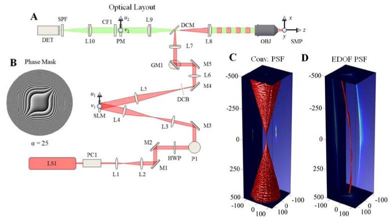
For clarity, the optical system can be conceptualized as two separate components: a) the illumination/targeting path and b) the imaging path. In the current design both a) and b) share a common microscope objective. This geometry is advantageous because it requires only add-on units to a traditional microscope, and can even be used for biological in vitro and in vivo biological imaging. The complete optical system layout is presented in Fig. 3(A) .
Fig. 3.
Design of extended depth of field (EDOF) microscope. Panel A: Experimental configuration of the joint SLM and extended-DOF imaging microscope for 3D targeting and monitoring. The detailed description of each component is described in the section 4.1. The phase aberration shown in panel B is the ideal diffractive optical element for the cubic-phase modulation and placed in an accessible region between L9 and L10 without affecting the illumination pupil. The experimental PSF of the imaging system is presented for the conventional microscope in panel C and the extended DOF microscope in panel D. The three-dimensional volume in panels C and D represent the 50% intensity cutoff of each axial plane and the axis units are in μm
The illumination path begins with the two-photon light source (LS1: Coherent Chameleon Ultra II), passes through a Pockels cell (PC1: Conoptics, Model 350-160) for fast control of the illumination intensity; followed by a telescope (L1: f1 = 50mm, L2: f2 = 150mm), a pair of dielectric mirrors for steering (M1 and M2), and is then redirected up a periscope (P1) and redirected (M3) through another telescope (L3: f3 = 50mm, L4: f4 = 100mm). The two telescopes served to expand the beam by a factor of six before illuminating the SLM (SLM: Holoeye, HEO1080p). An iris (not shown) is placed in front of the SLM to ensure that the no light strikes inactive regions of the SLM back-plane. The SLM is subsequently demagnified by 2.5x with the next telescope (L5: f5 = 250mm, L6: f6 = 100mm), with the undiffracted zero-order blocked (DCB), before being projected onto a pair of close-coupled X/Y galvonometric scanning mirrors (GM1). These mirrors center the beam through the scanning lens (L7: f7 = 50mm) of an Olympus BX-51 microscope. The beam is then reflected off a dichroic mirror (DCM: Chroma NIR-XR-RPC, reflects @ 700-1100nm) into the tube lens (L8: f8 = 180mm) and towards the microscope objective (OBJ: Olympus UMPLFLN 10x/0.3NA). The telescope distances are such that the SLM is conjugate to the microscope pupil. Here, the use of this relatively low NA objective will demonstrate one limiting case for the maximum useable axial extent of imaging the object space.
The imaging path uses OBJ to image the optical signal from the targets in the sample (SMP) onto the intermediate image plane located after the tube lens (L8) towards the camera (DET: Andor iXon Ultra2) using a 1:1 imaging relay (L9 and L10, f9 = f10 = 150mm). The relay is used to reimage the microscope pupil onto an accessible location where it can be manipulated independently from the illumination pupil. The CP wavefront coding mask (PM) is place one focal length behind L9 and one focal length in front of L10 along with a bandpass filter (CF1: Chroma, 510/40M). A short-pass filter (SPF: Chroma, HQ700SP-2P8 of OD6 @ λ ≥ 700nm) is placed in front of the detector to reject scattered and reflected light from the laser source. The PM itself is an 8-level phase mask etched into a quartz substrate (Chemglass Life Sciences, CGQ-0600-01) using conventional, multi-level lithographic techniques [27]. Note that with this imaging configuration, the effective α of the existing CP mask can be modulated by the selection of the focal lengths of the L9 and L10 lenses.
4.2 Mask design and total system calibration
The design of the cubic phase mask for the SLM microscope consists only of finding the suitable strength of the coefficient α to match the desired extended axial range and the required MTF [2, 17]. We designed our CP phase mask to work across both high and low NA objectives with a single instance of α. The choice of coefficient α = 200 (in a normalized coordinate system) for a phase mask of diameter Ø = 18mm was determined by simulation of the system, and approximately matching the desired performance of increasing the DOF a minimum of 20x. The size and strength of the phase mask was designed to accommodate a large number of objective designs (including Olympus, XLUMPLFL 20x/0.95WNA, Ø = 17.1mm, XLPLAN N 25x/1.05WNA, Ø = 15.1mm and Olympus, UMPLFLN 10x/0.3WNA). When used with the relatively low NA Olympus UMPLFLN 10x/0.3NA, the objective’s pupil apodizes the light such that the effective parameters of the phase mask are Ø = 9 mm and α = 25. In our current microscope the cubic phase mask, not the SLM, is the defocus-range limiting device.
For efficient illumination, we quantified the wavelength dependence of the phase modulation provided by the liquid crystal SLM, and characterized and corrected the effects of optical misalignment. To optimize SLM operation at λ = 760nm (i.e. to create a look-up table optimized to resolve a 2π phase stroke at λ = 760nm), calibration of applied voltage versus relative phase delay for the pixels in the SLM was performed by loading a Ronchi grating, varying the modulation depth and finding the associated diffraction efficiency [28]. Afterwards, centering of the SLM pattern to the optical axis was accomplished by scanning a phase grating that only filled a small portion of the full active area across the SLM in orthogonal directions and selecting the locations with peak diffraction efficiency into the 1st order. These searches gradually reduce in transverse scan length until a precise estimate of the optical axis, relative to the SLM, can be made.
For SLM pupil plane to object space calibration we first experimentally calibrated and corrected the axial displacement of the light beam when applying phase lenses to the SLM (see Appendix I for details and comparison with theoretical results). Then the appropriate affine transform matrix (i.e. the characterization of the transverse dimension) was estimated at varying depths by projecting a 2D array of points into object space. From these an axially dependent affine transform matrix was defined. As a result of these calibration steps, the imaging 3D PSF can be sampled for both the conventional optical imaging system and for the extended DOF optical system by illuminating a single point into bulk fluorescent material and shifting this point axially using the SLM for defocus as shown in Fig. 3(C) and 3(D), respectively.
5. Experimental results
Experimental results are reported for the case of three-dimensional targeting and imaging in transparent (Section 5.1) and scattering media (Section 5.2).
5.1 Three dimensional targeting and imaging for monitoring fluorescence in transparent samples
A demonstration of the system capabilities is given by illuminating a uniformly fluorescent sample made of a fluorescent dye dissolved in an agarose (3.5 grams of 1% agarose by weight in double-distilled deionized H2O loaded with yellow dye from a Sharpie Highlighter pen). A three-dimensional illumination pattern is projected 600µm below the cover-slip/agarose interface. The illumination pattern consists of two large features constructed from an ensemble of point targets. The north-west feature is a happy-face and the south-east feature is an unhappy-face, shown in Fig. 4(A) . With the CP mask placed in the optical imaging path, the image is aberrated as shown in Fig. 4(B). Using Wiener deconvolution, the intermediate, aberrated raw image can be processed to return an estimate of the target (Fig. 4(C)) that rivals the conventional image in quality.
Fig. 4.
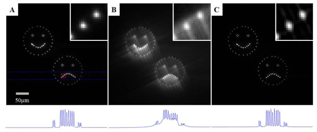
Panels A-C: Comparison of the focal plane images from (panel A) a conventional microscope, (panel B) the raw extended DOF image and (panel C) the restored extended DOF image. Note the contrast of these three images has been enhanced to have 0.1% of the pixels saturated to aid in visualization. Outlined in red in panel A is a region containing two points from the frown in the bottom right feature. A close up of this feature is given in the upper right region of each panel to provide a detailed examination of the imaging quality. Outlined in blue in panel A is a region containing 14 points. The maximum intensity projection of this region is shown below each panel showing that the digital restoration yields contrast similar to the conventional image.
To demonstrate the three-dimensional targeting and imaging capabilities of this microscope, the south-east feature is translated axially −500µm ≤ δz ≤ + 500µm from the classical focal plane (defined as ) in 4µm intervals while the north-west feature is held fixed in the focal plane (600μm below the surface of the media), as shown in Fig. 5(A) (movie available online). The results from a conventional imaging microscope are presented in Fig. 5(B). It is easy to observe the traditional barrier of observation which is present in SLM microscopy – indeed all traditional imaging-based microscopy techniques – where a rapid loss of imaging performance occurs as the illumination translates beyond the narrow focal plane. In contrast, the restored image from the extended DOF microscope is presented in Fig. 5(C), which shows a relative increase in the out-of-focus signal and tightly localized points regardless of axial location. This increase is quantified in Fig. 5(D) and includes the loss of illumination intensity as the target spot is shifted from the focal plane. For reference, the relative intensity of only the central lobe of the CP-PSF compared with the in-focus clear aperture PSF is 9.8%. We limited the range of |δz| to 500μm, as this was found to be the experimental limit after which the restored image was observed to be degraded because of the differences between the axially displaced CP-PSF from that of the ideal, in-focus CP-PSF used as the kernel in the restoration – as hinted at in the furthest ranges reported in Fig. 5(C).
Fig. 5.
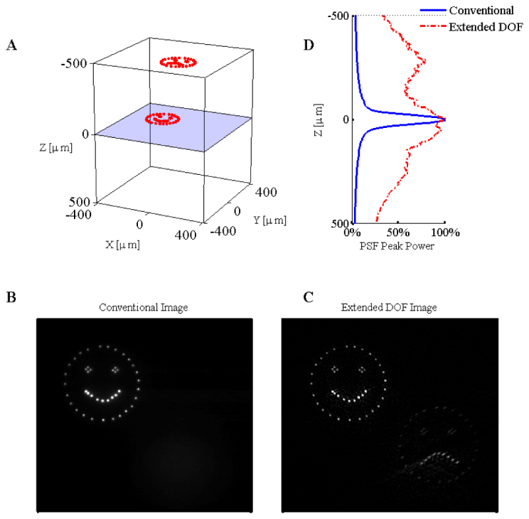
Experimental results for the three-dimensional SLM illumination in transparent media with both the conventional and extended depth of field microscope. The three-dimensional illumination pattern is shown in panel A. The relative intensity of the fluorescence as a function of depth is given to the right of panel A. The results from imaging the three-dimensional pattern in bulk fluorescent material are given for the conventional microscope (panel B) and the extended DOF microscope (panel C). Contrast was enhanced to saturate 0.1% of the pixel values in panels B and C ( Media 2 (13.3MB, AVI) ).
This example clearly demonstrates that points from multiple planes can now be imaged simultaneously. As the imaging PSF is now essentially axially invariant, the monitored optical signal can be easily found by searching for the associated peak in the restored image and summing the counts in a localized region. The optical signal collected from the spatially multiplexed targets is now captured simultaneously, with near-uniform efficiency regardless of the three-dimensional location – a distinguishing feature of this method.
5.2 Three-dimensional targeting and imaging for monitoring fluorescence in scattering samples
A problem frequently encountered in biological imaging is that the sample is embedded in highly scattering environment, so we examined the performance of this optical system in scattering medium (see Appendix II for details). In contrast to the results of Section 5.1, and as documented in Appendix II, the scattering reduces the illumination intensity exponentially with depth, and also blurs the emission. Therefore without further improvements a reduced operational range is expected for three-dimensional targeting and imaging.
The results for three-dimensional targeting and imaging are presented in Fig. 6 . As the target is located deeper in the scattering medium the total collected fluorescence decreases rapidly, the combined result of decreased illumination power reaching the target, and the emitted light being scattered and spatially dispersed. However, despite the presence of scattering in the imaging path, the deconvolution partially restores the image and results in an extension in the effective DOF and an increase in useable information. As can be seen experimentally from Fig. 6(D), the useable depth has increased for shallower axial positions with the extended DOF module. When going deeper in the tissue, the signal loss becomes dominated by scatter and not defocus, and approaches the same relative losses as the conventional microscope.
Fig. 6.
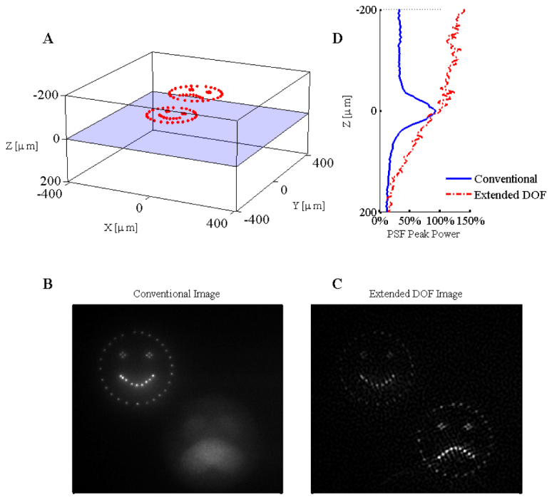
Experimental results for the three-dimensional SLM illumination in scattering media with both the conventional and extended depth of field microscope. The three-dimensional illumination pattern is shown in panel A. The focal plane is located 220µm below the surface of the scattering media. The relative intensity of the fluorescence as a function of depth is given to the right of panel A. The results from imaging the three-dimensional pattern in bulk fluorescent material are given for the conventional microscope (panel B) and the extended DOF microscope (panel C). Contrast was enhanced to saturate 0.02% of the pixel values in panels B and C ( Media 3 (6.6MB, AVI) ).
6. Discussion
The three-dimensional imaging microscope described here is built upon the foundation of two independent optical techniques. First, we have temporally and spatially deterministic illumination from a modulating device (e.g. the Spatial Light Modulator), such that emission from the sample is limited to known regions in 3D and time prior to detection or sensing. Second, the optical signal emitted from the illuminated regions is collected using an optically efficient imaging system which produces images of near-equivalent quality regardless of the source emission position in the sample volume (i.e. extended Depth of Field). Taken alone, the three-dimensional illumination strategy requires a solution for efficiently acquiring optical signal from anywhere within the sample volume. Conversely, the extended DOF imaging optics requires a solution for disambiguating the sources of emission so that signal can be assigned to specific locations within the sample volume. The joint implementation of these complementary techniques overcomes each of the individual limitations and creates a complete, flexible solution. Indeed, it is the prior knowledge provided by the user-controlled illumination device that is integral to providing context to the images acquired by the extended Depth of Field microscope. While the experimental demonstration here included a SLM as the source of the structured illumination, alternative methods for projecting patterns such as light-sheet microscopy are equally suited for this fundamental improvement by coupling with the extended Depth of Field microscope.
Using simulations (see Fig. 2(A)), we reported a rule-of-thumb design criteria based upon maintaining a uniform signal within the main lobe of the CP-PSF throughout the spanned axial range, and found this to be α ≥ ½ |Ψ|. We also explored the experimental performance of the system under a more stringent, restoration metric. Here, performance was measured by the ability to accurately restore the original image by deconvolution with a single, invariant kernel based on the in-focus CP-PSF. With this alternate metric, the approximated best performance on restored signals was found experimentally to be α ≥ 2 |Ψ|, a design factor of ~4x greater than the less restrictive, conserved lobe signal constraint. The difference between these two results can be reconciled by examination of the movie in Fig. 1. For example, when |Ψ| = 2α a PSF similar to the CP-PSF - including the single, dominant peak - is indeed observed. However the detailed pattern of the side-lobes is lost at such extreme defocus. Not until |Ψ| < α do the side-lobes begin to regain the detailed form present when the system is focused. As a result, because we used the experimental, in-focus CP-PSF for restoring the images we have become slightly sensitive to this variation in side-lobe quality – a well-known consequence of using imprecise deconvolution kernels in extended DOF imaging [29]. This more restrictive scenario with the objective of image restoration therefore results in the suggestion of α ≥ 2 |Ψ|.
Unsurprisingly, the experimental 3D targeting and imaging demonstrated here show that imaging through transparent media (Section 5.1) is more reliable than imaging in scattering media (Section 5.2). However, it must be emphasized even in scattering samples, the method applied here still increases the effective useful collection volume several fold compared to conventional imaging. In applications where fluorescence labeling is sparse (i.e. specifically labeled dyes or the use of genetic encoding) the ratio of fluorescence in the target to that of the background will become much more favorable and this will increase the allowable imaging depth and DOF extension. In addition, for the specific case of working with scattering media, continued work can implement a weighted Gershberg-Saxon (wGS) algorithm [30] for compensating scattering losses by providing an axial-dependent increase in the target illumination intensity. It should be noted that alternative phase mask implementations are available for extended DOF. Examples include the super-position of multiple Fresnel zone plates [13], Bessel-beams [12], and other families of beams with extended propagation-invariance [31, 32]. It is possible that for specific tasks (e.g. point targeting versus extended object targeting) an alternative optimal solution may be identified.
7. Conclusion
We have presented here a method which is free from any mechanical motion to create both a three-dimensional targeting pattern as well as three-dimensional images of the optical signal. The technology enabling this device relies on independent modulation of the transverse phase of the optical beam on both the illumination and imaging side of the microscope, using a spatial light modulator and a phase mask, respectively. The method presented here is amenable to fast imaging and is not restricted to illuminating or imaging the sample in a sequential planar pattern. The microscope was tested and performance verified in both transparent and scattering media. Because it conceptually consists of only ‘bolt-on’ modules to existing microscopes, the technology is open to potential use for in vivo imaging. Therefore we believe this system is unique in providing vibration-free equipment for biological research in a package which does not require a massive redesign of microscopes in existing laboratories and could therefore be widely applicable for the study of living biological samples.
Acknowledgments
Supported by the Kavli Institute for Brain Science, NEI, NINDS, NIHM, NIDA, Keck Foundation and NARSAD. This material is based upon work supported by, or in part by, the U. S. Army Research Laboratory and the U. S. Army Research Office under contract number W911NF-12-1-0594.
8. Appendix I: Illumination/targeting pattern calibration procedure
The procedures for calibrating the projection of the phase-encoded SLM onto the sample volume and imaging detector are disclosed below. These procedures are valuable for accommodating optical misalignment and maintaining stable performance over time.
8.1 Calibration of axial translation
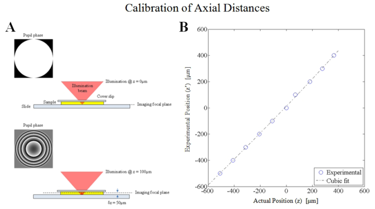
The axial distances are calibrated through a procedure where the reflection from a moveable dielectric interface is actively focused after applying a variable amount of defocus phase to the SLM. The optical configuration is given in Fig. 7
Fig. 7.
The defocus calibration method requires that the back-reflection from the sample/slide interface is in focus on the imaging path. When zero defocus phase is applied at the SLM (pupil plane), the in-focus image is at the focal plane (by definition). A defocus phase was applied at the SLM to translate the target illumination in 100µm intervals. For each defocus phase on the SLM, the sample stage is translated axially until the back-reflection is focused using the imaging path. The sample translation is recorded as the experimental z position for each expected z position. Comparison between the expected axial position versus the experimental position are shown in the plot above. The theoretical curve predicts distances which are on average 3.2% larger than the experimentally determined axial position.
. To begin, a defocus phase is placed on the SLM which should provide a target at (x,y) = (0,0) in plane z using,
| (7) |
Where the coefficient and Zernike modes are listed in given in [23] and , .
This expansion of the defocusing aberration into higher-order Zernike polynomials is necessary for both three-dimensional imaging as well as imaging in biological tissue with refractive index mismatches [23, 25]. Using this form for defocus aberration, the theoretical curve is in good agreement with the experimental measurements shown in Fig. 7. For improved accuracy, a fit of the experimental curve is taken as to be used for calibration of the experimental axial distance where the coefficients are found to be a = 2.8e-8, b = 7.0e-5, c = 1.032, and d = 12.08.
8.2 Calibration of transverse coordinates
A second calibration is performed for estimating the transverse position of the targeting pattern relative to its expected position on the imaging detector. Sources of these deviations can be due to SLM rotation relative to the camera, misalignment of optical components along the optical axis as well as the oblique incidence angle of the optical beam to the SLM. In this sense, the calibration step is meant to remove any rotation, shear or other transformation which can be considered affine. For the transverse pattern calibration a target pattern is projected and the affine transformation is calculated from the experimental measurement relative to the ideal position. Using the expected coordinate positions x, y and the experimental positions and for this target pattern the transform is defined as,
| (8) |
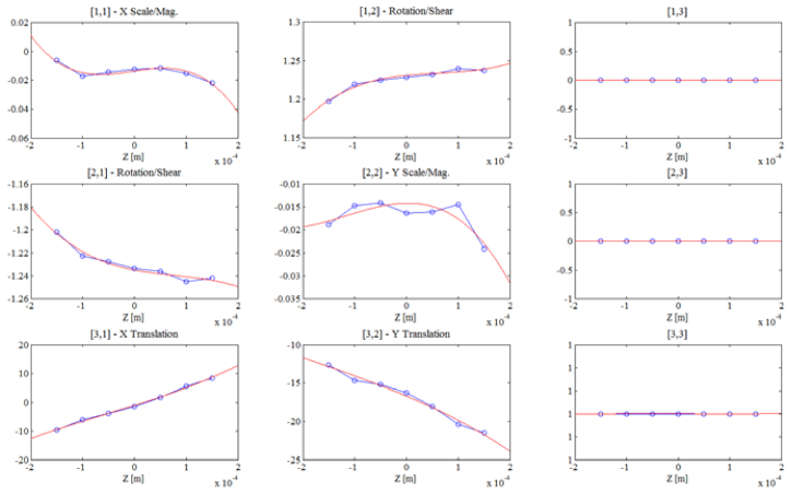
Because optical misalignment can lead to depth-dependent aberrations, this transverse coordinate transformation is defined to be a function of the target depth z. In our experiments a minimum of seven axial planes are used to calibrate the axial dependence of this affine transform matrix, and each coefficient of the matrix is fit to a curve as shown in Fig. 8
Fig. 8.
The axial dependence of the 3x3 affine transformation matrix as experimentally determined from imaging in a bulk slab of fluorescent material.
to provide a smoothly varying affine transform at any continuous axial position.
Using both the axial and transverse calibration, the completely calibrated target illumination for the SLM display is found using Eq. (4).
9. Appendix II: Scattering properties of the phantom samples
The scattering phantom consists of 3.5 grams of the fluorescent dye solution (50% by weight), 0.5 grams of whole, pasteurized milk (7% by weight) and 3.0 grams of the 1% agarose mixture (43% by weight). Total losses from the illumination and imaging for both the transparent and the scattering sample are characterized in Fig. 9
Fig. 9.
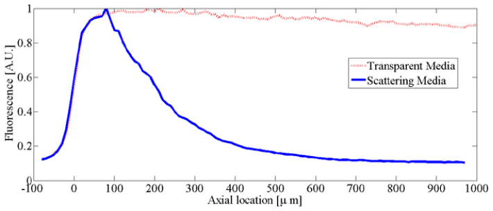
The normalized fluorescence collected from an individual target as the sample is translated axially so that the sample depth is increased. At large depths a slight decrease in the collected signal is observed for the transparent sample while the scattering sample experiences near extinction of the signal by 500µm.
.
References and links
- 1.Alivisatos A. P., Chun M., Church G. M., Greenspan R. J., Roukes M. L., Yuste R., “The Brain Activity Map Project and the challenge of Functional Connectomics,” Neuron 74(6), 970–974 (2012). 10.1016/j.neuron.2012.06.006 [DOI] [PMC free article] [PubMed] [Google Scholar]
- 2.Dowski E. R., Jr, Cathey W. T., “Extended depth of field through wave-front coding,” Appl. Opt. 34(11), 1859–1866 (1995). 10.1364/AO.34.001859 [DOI] [PubMed] [Google Scholar]
- 3.Nikolenko V., Watson B. O., Araya R., Woodruff A., Peterka D. S., Yuste R., “SLM Microscopy: Scanless two-photon imaging and photostimulation using spatial light modulators,” Front Neural Circuits 2, 5 (2008). 10.3389/neuro.04.005.2008 [DOI] [PMC free article] [PubMed] [Google Scholar]
- 4.Voie A. H., Burns D. H., Spelman F. A., “Orthogonal-plane fluorescence optical sectioning: three-dimensional imaging of macroscopic biological specimens,” J. Microsc. 170(3), 229–236 (1993). 10.1111/j.1365-2818.1993.tb03346.x [DOI] [PubMed] [Google Scholar]
- 5.Huber D., Keller M., Robert D., “3D light scanning macrography,” J. Microsc. 203(2), 208–213 (2001). 10.1046/j.1365-2818.2001.00892.x [DOI] [PubMed] [Google Scholar]
- 6.Huisken J., Swoger J., Del Bene F., Wittbrodt J., Stelzer E. H. K., “Optical sectioning deep inside live embryos by selective plane illumination microscopy,” Science 305(5686), 1007–1009 (2004). 10.1126/science.1100035 [DOI] [PubMed] [Google Scholar]
- 7.Holekamp T. F., Turaga D., Holy T. E., “Fast three-dimensional fluorescence imaging of activity in neural populations by objective-coupled planar illumination microscopy,” Neuron 57(5), 661–672 (2008). 10.1016/j.neuron.2008.01.011 [DOI] [PubMed] [Google Scholar]
- 8.Göbel W., Kampa B. M., Helmchen F., “Imaging cellular network dynamics in three dimensions using fast 3D laser scanning,” Nat. Methods 4(1), 73–79 (2007). 10.1038/nmeth989 [DOI] [PubMed] [Google Scholar]
- 9.Grewe B. F., Langer D., Kasper H., Kampa B. M., Helmchen F., “High-speed in vivo calcium imaging reveals neuronal network activity with near-millisecond precision,” Nat. Methods 7(5), 399–405 (2010). 10.1038/nmeth.1453 [DOI] [PubMed] [Google Scholar]
- 10.Cheng A., Gonçalves J. T., Golshani P., Arisaka K., Portera-Cailliau C., “Simultaneous two-photon calcium imaging at different depths with spatiotemporal multiplexing,” Nat. Methods 8(2), 139–142 (2011). 10.1038/nmeth.1552 [DOI] [PMC free article] [PubMed] [Google Scholar]
- 11.Katona G., Szalay G., Maák P., Kaszás A., Veress M., Hillier D., Chiovini B., Vizi E. S., Roska B., Rózsa B., “Fast two-photon in vivo imaging with three-dimensional random-access scanning in large tissue volumes,” Nat. Methods 9(2), 201–208 (2012). 10.1038/nmeth.1851 [DOI] [PubMed] [Google Scholar]
- 12.Lit J. W. Y., Tremblay R., “Focal depth of a transmitting axicon,” J. Opt. Soc. Am. 63(4), 445–449 (1973). 10.1364/JOSA.63.000445 [DOI] [Google Scholar]
- 13.Indebetouw G., Bai H., “Imaging with Fresnel zone pupil masks: extended depth of field,” Appl. Opt. 23(23), 4299–4302 (1984). 10.1364/AO.23.004299 [DOI] [PubMed] [Google Scholar]
- 14.Kao H. P., Verkman A. S., “Tracking of single fluorescent particles in three dimensions: use of cylindrical optics to encode particle position,” Biophys. J. 67(3), 1291–1300 (1994). 10.1016/S0006-3495(94)80601-0 [DOI] [PMC free article] [PubMed] [Google Scholar]
- 15.Chi W., George N., “Electronic imaging using a logarithmic asphere,” Opt. Lett. 26(12), 875–877 (2001). 10.1364/OL.26.000875 [DOI] [PubMed] [Google Scholar]
- 16.Greengard A., Schechner Y. Y., Piestun R., “Depth from diffracted rotation,” Opt. Lett. 31(2), 181–183 (2006). 10.1364/OL.31.000181 [DOI] [PubMed] [Google Scholar]
- 17.Bagheri S., Silveira P. E. X., Narayanswamy R., de Farias D. P., “Analytical optical solution of the extension of the depth of field using cubic-phase wavefront coding. Part II. Design and optimization of the cubic phase,” J. Opt. Soc. Am. A 25(5), 1064–1074 (2008). 10.1364/JOSAA.25.001064 [DOI] [PubMed] [Google Scholar]
- 18.Polynkin P., Kolesik M., Moloney J. V., Siviloglou G. A., Christodoulides D. N., “Curved plasma channel generation using ultraintense Airy beams,” Science 324(5924), 229–232 (2009). 10.1126/science.1169544 [DOI] [PubMed] [Google Scholar]
- 19.Ji N., Milkie D. E., Betzig E., “Adaptive optics via pupil segmentation for high-resolution imaging in biological tissues,” Nat. Methods 7(2), 141–147 (2010). 10.1038/nmeth.1411 [DOI] [PubMed] [Google Scholar]
- 20.Vellekoop I. M., Mosk A. P., “Universal optimal transmission of light through disordered materials,” Phys. Rev. Lett. 101(12), 120601 (2008). 10.1103/PhysRevLett.101.120601 [DOI] [PubMed] [Google Scholar]
- 21.Nikolenko V., Poskanzer K. E., Yuste R., “Two-photon photostimulation and imaging of neural circuits,” Nat. Methods 4(11), 943–950 (2007). 10.1038/nmeth1105 [DOI] [PubMed] [Google Scholar]
- 22.Packer A. M., Peterka D. S., Hirtz J. J., Prakash R., Deisseroth K., Yuste R., “Two-photon optogenetics of dendritic spines and neural circuits,” Nat. Methods 9(12), 1202–1205 (2012). 10.1038/nmeth.2249 [DOI] [PMC free article] [PubMed] [Google Scholar]
- 23.Anselmi F., Ventalon C., Bègue A., Ogden D., Emiliani V., “Three-dimensional imaging and photostimulation by remote-focusing and holographic light patterning,” Proc. Natl. Acad. Sci. U.S.A. 108(49), 19504–19509 (2011). 10.1073/pnas.1109111108 [DOI] [PMC free article] [PubMed] [Google Scholar]
- 24.Denk W., Strickler J. H., Webb W. W., “Two-photon laser scanning fluorescence microscopy,” Science 248(4951), 73–76 (1990). 10.1126/science.2321027 [DOI] [PubMed] [Google Scholar]
- 25.Botcherby E. J., Juškaitis R., Booth M. J., Wilson T., “An optical technique for remote focusing in microscopy,” Opt. Commun. 281(4), 880–887 (2008). 10.1016/j.optcom.2007.10.007 [DOI] [Google Scholar]
- 26.W. J. Smith, Modern Optical Engineering, 3rd Ed. (McGraw-Hill, 2000). [Google Scholar]
- 27.G. J. Swanson, “Binary Optics Technology: The theory and design of multi-level diffractive optical elements,” MIT/Lincoln Laboratories Technical Report 854 (1989).
- 28.Zhang Z., Lu G., Yu F., “Simple method for measuring phase modulation in liquid crystal television,” Opt. Eng. 33(9), 3018–3022 (1994). 10.1117/12.177518 [DOI] [Google Scholar]
- 29.Demenikov M., Harvey A. R., “A technique to remove image artefacts in optical systems with wavefront coding,” Proc. SPIE 7429, 74290N (2009). 10.1117/12.825923 [DOI] [Google Scholar]
- 30.Persson M., Engström D., Goksör M., “An algorithm for improved control of trap intensities in holographic optical tweezers,” Proc. SPIE 8458, 84582W–, 84582W-7. (2012), . 10.1117/12.930014 [DOI] [Google Scholar]
- 31.Prasad S., Pauca V. P., Plemmons R. J., Torgersen T. C., van der Gracht J., “Pupil-phase optimization for extended focus, aberration corrected imaging systems,” Proc. SPIE 5559, 335–345 (2004). 10.1117/12.560235 [DOI] [Google Scholar]
- 32.Piestun R., Schechner Y. Y., Shamir J., “Propagation-invariant wave fields with finite energy,” J. Opt. Soc. Am. A 17(2), 294–303 (2000). 10.1364/JOSAA.17.000294 [DOI] [PubMed] [Google Scholar]


