Abstract
Advanced medical imaging technologies provide a wealth of information on cardiac anatomy and structure at a paracellular resolution, allowing to identify micro-structural discontinuities which disrupt the intracellular matrix. Current state-of-the-art computer models built upon such datasets account for increasingly finer anatomical details, however, structural discontinuities at the paracellular level are typically discarded in the model generation process, owing to the significant costs which incur when using high resolutions for explicit representation. In this study, a novel discontinuous finite element (dFE) approach for discretizing the bidomain equations is presented, which accounts for fine-scale structures in a computer model without the need to increase spatial resolution. In the dFE method this is achieved by imposing infinitely thin lines of electrical insulation along edges of finite elements which approximate the geometry of discontinuities in the intracellular matrix. Simulation results demonstrate that the dFE approach accounts for effects induced by microscopic size scale discontinuities, such as the formation of microscopic virtual electrodes, with vast computational savings as compared to high resolution continuous finite element models. Moreover, the method can be implemented in any standard continuous finite element code with minor effort.
I. Introduction
Computational modeling of cardiac electrophysiology at the tissue and organ scale relies mostly on continuum formulations which characterize emergent bioelectric phenomena such as wavefront propagation at a macroscopic size scale. Such models are built upon the assumption of an electric syncytium, that is, diffusive material properties of the tissue are continuous. The validity of this assumption at a macroscopic size scale is supported by the successful application of macroscopic models such as the cardiac bidomain model [1], whose predictions are very well in line with experimental observations [2]. When viewed at a finer microscopic size scale though, cardiac tissue is a discrete medium in which electrical impulses propagate discontinuously [3]. Under healthy conditions during normal propagation there are no direct significant manifestations of microscopic discontinuities which would play a major role at the tissue and organ scale, however, when external electric fields are applied [4] or when discontinuities become more pronounced as it may be the case under pathological conditions, conduction pathways at the microscopic size scale are altered to an extent which can cause noticeable effects at the macroscopic size scale as well. A particularly important case is fibrosis, a degenerative progressive disease in which connective tissue invades the intracellular matrix thus interrupting the intracellular space. While such disruptive lines or layers can be very thin, longitudinally they may grow over several space constants. Such elongated fibrotic inlays can induce discontinuous zig-zag propagation patterns which are associated with significant conduction delays [5]. Thus, despite their thinness, such structures lead to an apparent conduction slowing which shortens wavelength and induces wavefront fractionation, both factors which are known to promote the formation of arrhythmias.
In continuum models such fine-scale structures are not explicitly accounted for, particularly in larger tissue preparations or in whole organ models. The choice of spatial resolution, h, in continuum models is mainly dictated by the physics of the model equations and the level of geometric detail one wishes to account for. In terms of physical constraints upon h, the fast transients involved in electrical activation last less than 1 ms which translates into steep wave fronts of extent < 1 mm, necessitating high spatio-temporal resolution. Current state-of-the-art organ scale models use fairly high paracellular resolutions with h ≈ 100 μm which correspond roughly to the length of a single cell [6]. While such high resolutions suffice to accommodate explicit representations of fine structures such as endocardial trabeculae or major vessels in the myocardium, they are insufficient to spatially resolve thin, but elongated fibrotic textures which may cause noticeable effects at a global macroscopic size scale.
Using standard continuous finite element (FE) techniques structures at such a fine size scale can only be represented explicitly by using sufficiently high spatial resolutions, which may be prohibitive in terms of the computational costs involved. In this study, a novel computationally efficient discontinuous FE (dFE) bidomain modeling approach is presented, which accommodates fine-scale structural detail without the need to increase spatial resolution. Instead, standard discretizations (h ≈ 100 μm) are used upon which the finer structures at size scales << h are conformally projected. Insulation is enforced along the conformal projections in the intracellular space through splitting of FE nodes, while the interstitial space remains coupled. The method provides increased flexibility by allowing to account for micro-structural details in bidomain simulations with minimal extra computational cost.
II. Methods
A. Discontinuous Finite Element Approach
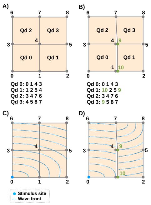
The basic idea of the proposed dFE technique is to model microscopic conduction barriers as infinitely thin insulating lines or surfaces in a conformal FE mesh. Geometry and topology of such barriers are extracted from high resolution images and projected onto a coarse FE mesh by marking those element edges/faces which best approximate the topology of conduction barriers. Across the marked edges, electrical insulation of the intracellular space is enforced via no-flux boundary conditions which are imposed by decoupling nodes shared between adjacent elements. This is achieved by assigning a new nodal index to a shared node in a finite element located at one side of an insulating line/surface, while keeping the original nodal index at the other side. Spatial coordinates of the split nodes remain unchanged, since the width of the isolating structure is assumed to be infinitely small. The basic principle is illustrated in Fig. 1A)-D). Renumbering of nodes 1 and 4 in elements Qd1 and Qd3 imposes no-flux boundary condition, thus impeding wavefront propagation across the insulating boundary. In this study we aim at developing the discontinuous FE method for 2D meshes. We start off from pure quadrilateral meshes which are derived from segmented decimated images of histologically processed tissue slices.
Fig. 1.
Upper panels show element connectivity of continuous FE (left) and dFE (right) mesh. Lower panels indicate wave front propagation patterns for both cases. In the right dFE panel nodes 1 and 4 are decoupled, preventing impulse propagation across the line 1-4-7, only node 7 allows transduction. Impact of nodal splitting upon propagation pattern when stimulating node 0 is illustrated using artificial isochrones.
B. Governing Equations
The bidomain equations in the elliptic-parabolic form are given by
| (1) |
| (2) |
| (3) |
| (4) |
where ϕi and ϕe are the intracellular and extracellular potentials, respectively, Vm = ϕi − ϕe is the transmembrane voltage, σi and σe are the anisotropic intracellular and extracellular conductivity tensors, respectively, σb is the isotropic conductivity of a surrounding bath or of larger interstitial cleft spaces, β is the bidomain surface-to-volume ratio, Cm is the membrane capacitance per unit area, and Iion is the ionic current density which depends on Vm and a state vector, η.
At tissue boundaries, no-flux boundary conditions are imposed for ϕi, with the potential ϕe and the normal component of the extracellular current being continuous. At boundaries of the conductive bath surrounding the tissue, no-flux boundary conditions on ϕe are imposed.
In a general case the sizes of intracellular and extracellular domain are unequal, necessitating a domain mapping operator for data transfer between the domains. This is the case in the presence of a bath or larger cleft spaces within the myocardium, or, as in this study, when additional insulating boundary conditions are applied to the intracellular domain. The mapping operator, P, is shown in Eq. 6, which gives the FE discretization of the bidomain equations.
| (5) |
| (6) |
where K* and M* are stiffness and mass matrices, respectively, with * = e|i being either the extracellular space, Ωe, or the intracellular space, Ωi, P is a prolongation operator from Ωi to Ωe, its transpose, PT, is a restriction operator from Ωe to Ωi, and Im is the transmembrane current.
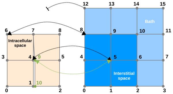
In the continuous case in absence of a bath, P and PT are 1:1 injections. In presence of a bath, data are mapped 1:1 within the myocardium and no mapping is performed in the bath. In the discontinuous case, within the myocardium, data are either mapped 1:1 or 1: n at split nodes, where n is the multiplicity of the splitting (Fig. 2).
Fig. 2.
Generalized dFE mapping between intracellular domain Ωi, and extracellular domain Ωe in presence of a bath. Source terms from nodes 4 and 9 of the Ωi grid are mapped onto node 5 of the Ωe grid, i.e. node 5 in domain Ωe “sees” two source points. Conversely, nodes 4 and 9 in domain Ωi sense the same extracellular potential Ωe from node 5. Nodes which were not split, e.g. 6, map 1:1 to an extracellular node. Pure bath nodes such as 12 are not mapped.
C. Construction of a 2D Test Case
1) Sectioning, Histological Staining and Image Acquisition
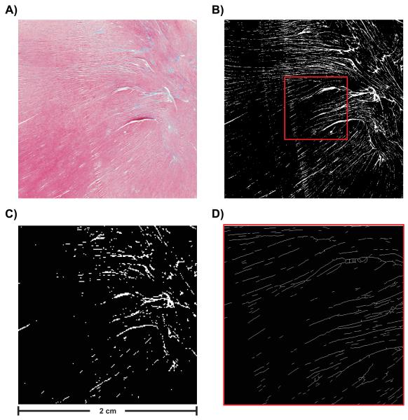
For the sake of testing the proposed dFE method a 2D test case is constructed. Rabbit ventricles were embedded in paraffin wax, microtome sliced and stained using Masson’s trichrome staining (see Fig. 3A). Slices were imaged at high resolution. A representative, artefact-free slice was chosen from which a square region of 2000 × 2000 pixels, pixel size of 10 × 10 μm2, was selected for model construction (Fig. 3A).
Fig. 3.
(A) Histological image selected for building FE meshes. Image consists of 2000 × 2000 pixels (pixel size 10 × 10 μm2). (B) Segmentation result for high resolution image. (C) Segmentation result for lower resolution image. Image consists of 200 × 200 pixels (pixel size 100 × 100 μm2). (D) Visualization of extracted skeleton showing a magnification of the area indicated by the red square in panel B).
2) Image Segmentation
Trichrome stain labels myocytes pinkish-red and connective tissue bluish-green, interstitial cleft spaces remain unstained (Fig. 3A). For the construction of a computer model only two spaces are discriminated, the intracellular space consisting of myocytes, and the interstitial space, consisting of cleft space and connective tissue. Fig. 3B) shows binarization results, with connective tissue and cleft spaces appearing in white and myocytes in black.
3) Downsampling
For the dFE approach a coarse representation of a domain is needed upon which fine scale details are projected. Such a coarse representation was derived from the segmented high resolution image (Fig. 3B) by downsampling the image to 200 × 200 pixels (pixel size 100 × 100 μm2) (Fig. 3C), a standard resolution in state-of-the-art models [6], [7]. This reduction entailed a loss of information. Only structures > 100 μm were retained and explicitly represented in the FE grid, any structures < 100 μm disappeared.
4) Skeletonization
A skeletonization algorithm was employed to extract the network of connective tissue from the high resolution image. Fig. 3D) shows the skeletonization result. Note that the skeletonized microstructure is visualized as thin lines of 1 pixel width. The topology of the connective tissue network is given now as a set of line segments which is a suitable format for being projected onto a 2D FE mesh.
5) Fiber Detection
Prevailing myocyte orientations aka “fiber orientations” were extracted by converting the color high resolution image to a grayscale image. The grayscale image was downsampled and an intensity gradient method [8] was applied to both high and low resolution images to compute fiber orientations.
D. Mesh Generation and Post-processing
1) Generation of High and Lower Resolution Meshes
Two sets of FE meshes were generated directly from the segmented images shown in Fig. 3B) and C) [9]. In this process, each pixel was replaced by a 2D quadrilateral element of the same size, i.e. 10 × 10 μm2 for the high resolution image and 100 × 100 μm2 for the low resolution image. In the FE mesh of the intracellular grid only those pixels were included which have been previously identified as myocardium, pixels classified as interstitial space or connective tissue were discarded whereas in the FE mesh of the extracellular grid, all pixels were considered. That is, two grids were generated, a high resolution grid which accounted for all structural detail present in the histological images (Fig. 3B), and a coarser grid which accounted only for those structures which could be spatially resolved at the coarser resolution (Fig. 3C).
2) Skeleton Projection
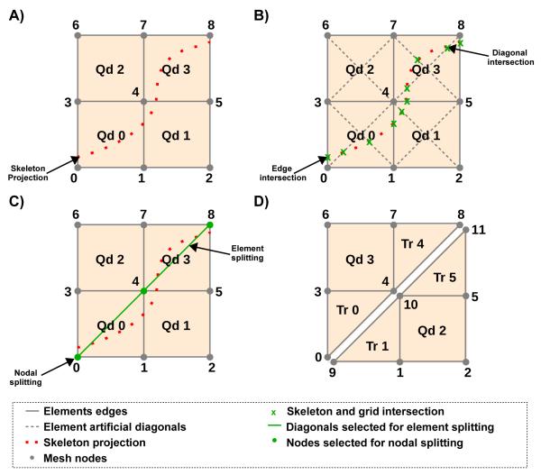
To account for fine-scale structures in the coarse FE mesh the line segments computed during the skeletonization procedure are projected onto the mesh (See Fig. 4A). In a first sweep of this process, the coarse mesh is searched for intersections of element edges and element diagonals with the line segments (Fig. 4B). Information on intersections, such as the numbers of two elements sharing an intersected edge, the element number of elements with intersected diagonals and the index of the node closest to the intersection are stored.
Fig. 4.
A) Projection of skeleton onto coarse grid. B) Search for edge and diagonal intersections. C) Nodes selected for splitting are highlighted in green. Diagonals selected for splitting the quadrilateral elements into two triangles are highlighted as green lines. D) Modified grid after nodal and element splitting.
3) Nodal and Element Splitting
By the end of the skeleton projection, all elements with intersections were processed. Those nodes in elements with intersections were marked for splitting (See Fig. 4C). Depending on number and location of marked nodes within the element, different procedures were implemented. In those rare cases where all 4 nodes of a quad were marked, the element was removed from the mesh. Special treatment was implemented for cases when two marked nodes were not directly connected by an element edge, i.e. the nodes were located at diagonals of a quad. In this case the FE mesh was modified by splitting the quadrilateral element into two triangular elements, and by splitting the nodes that span the edge shared by the two triangular elements (See Fig. 4C) and C). This procedure allows smoother projections which avoid unnecessarily jagged fault lines (Fig. 4D). In all other cases no grid modifications were required since electrical insulation across the assumed conduction barriers can be achieved by decoupling along pre-existing edges of the quadrilateral element.
By the end of the splitting procedure a hybrid mesh, with quadrilateral and triangular elements, is generated. Information on nodal splitting is stored in a list, which holds the indices of the nodes marked for splitting, the indices of the elements where these nodes should be split and the new nodal index that should be attributed to these nodes. This list is used as input to the simulator to perform the nodal splitting on the fly. The nodal splitting is done via renumbering of nodes in elements of the intracellular grid.
E. Simulation Setups
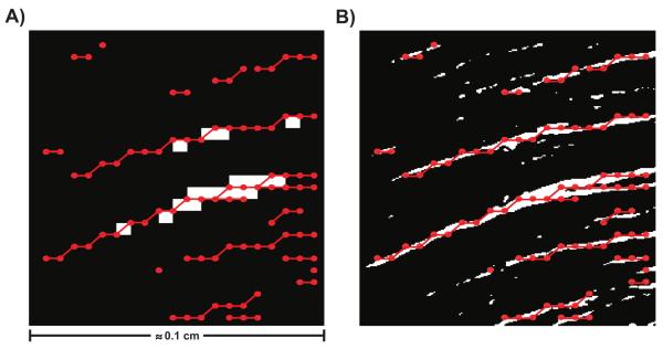
To evaluate the dFE method three different setups were used: i) a fine mesh (FM), consisting of 2000 × 2000 quadrilateral elements with an edge length of 10 μm capturing full micro-structural detail (see Fig. 3B); ii) a coarser mesh (CM), consisting of 200 × 200 quadrilateral elements with an edge length of 100 μm, where only those major structures were explicitly represented which could be resolved at the lower resolution (see Fig. 3C); iii) the CM was used, but the dFE method was applied (dCM) which led to the insertion of 18377 additional nodes. The total number of nodes, N, in each FE grid were 4004001, 40401 and 58778 for FM, CM and dCM, respectively. A comparison between the setups is shown in Fig. 5. In panel A) the discontinuous structures represented by the decoupled nodes are presented over the CM. Note that the fine structures present in the FM are not present in the CM, but are included as the insulating lines shown in red, that were created by decoupling the highlighted nodes. In panel B) the representation of the discontinuous structures are compared against the actual fine structures that are present in the FM. Note that, although the representation is slightly jagged, it matches the original structures fairly well. Fine structures that were below 200 μm of diameter were removed from the CM and dCM setups to reduce computational cost. Such small structures do not induce virtual electrodes polarizations, as shown in [10], and thus can be ignored. Since numerical parameters were kept constant throughout all simulation runs, the relative computational costs are proportional to N. That is, the computational cost of CM and dCM relative to the FM were 1.00% and 1.46%, respectively.
Fig. 5.
Comparison between the setups. A) dCM setup, which consists of the projected discontinuities, represented by the red dotted lines, over the CM setup. B) Comparison between the representation of the discontinuous structures on the dCM setup and the actual structures on the FM setup.
The Beeler-Reuter-Drouhard-Roberge model as modified in [11] was employed to describe the cellular dynamics of a mammalian ventricular cell. To distinguish differences between FM and dFE simulations which arise due to the representation of structural discontinuity and the averaged representation of fiber orientations, two sets of conductivities were used. An isotropic setup, using intracellular and extracellular conductivities of 0.11963 S/m and 0.625 S/m, respectively, served to assess differences attributable solely to the alternative representation of structural discontinuity. Alternatively, an anisotropic setup in which longitudinal conductivities in the intracellular and extracellular space were set to 0.11963 S/m and 0.625 S/m, respectively, and transverse conductivities to 0.02621 S/m and 0.236 S/m, respectively. This setup can be considered to be more realistic by accounting for anisotropy, however, for gauging the quality of approximation of the dFE approach it is less suitable, since additional discrepancies will incur due to the downsampling of the fiber field. Bidomain surface-to-volume ratio β and membrane capacitance Cm were chosen as 1400 cm−1 and 1 μF/cm2, respectively.
Wavefront propagation was initiated by electric field stimulation applied via two line electrodes located at top and bottom of the domain, as shown at the right bottom of Fig. 6. In line with our goal of evaluating the quality of the dFE approximation relative to high resolution models, the application of an electric field has been chosen as a test case since induced virtual electrode polarization patterns [4] are highly sensitive to the presence of structural discontinuity. In particular, a field strength of 4 V/cm was applied for 2 ms which was sufficiently strong to elicit supra-threshold responses around fine-scale discontinuities. Cathodal and anodal stimulation were implemented as time-varying Dirichlet boundary conditions along which Φe = 0 mV and Φe = 8000 mV was enforced during the stimulus period. After the end of the stimulus, the anode was kept grounded while the cathodal Dirichlet boundary condition was removed, i.e. extracellular potentials Φe along the top edge of the domain could float which is analog to opening the stimulation circuit in an experimental setting.
Fig. 6.
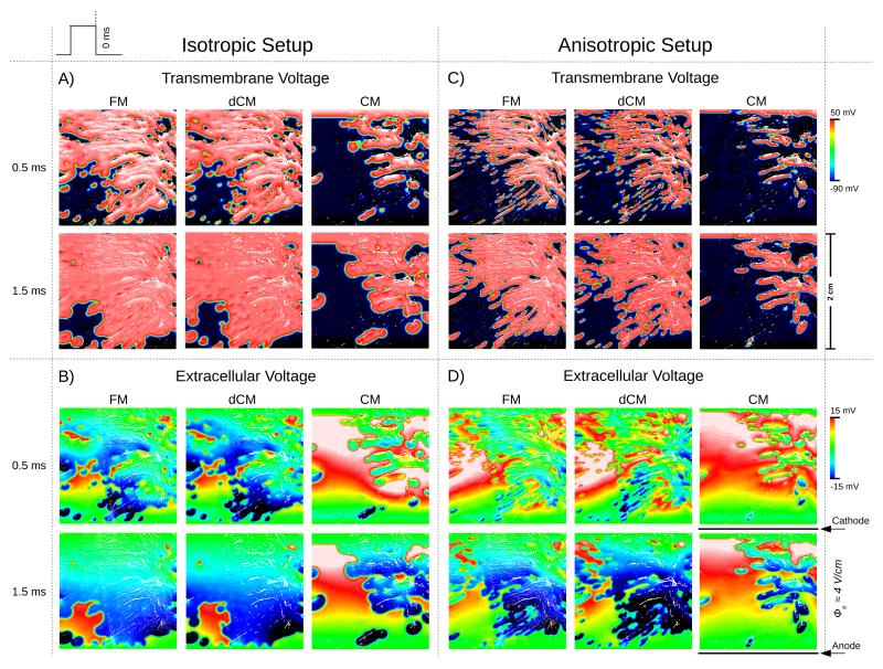
Spatial distribution of the transmembrane potential (A and C) and extracellular potential (B and D), when using the isotropic (A and B) and anisotropic (C and D) setups. Results are shown for all three models, FM, CM and dCM, at 0.5 ms and 1.5 ms post-shock.
F. Evaluation of discontinuous FE Method
The dFE method was evaluated by comparing against the FM grid. Potential benefits of the dFE method were investigated by assessing whether and as to which degree the dFE method provides more accurate predictions of activation patterns, i.e. differences to the reference FM grid are reduced, and the savings in terms of computational cost.
Simulation results were qualitatively evaluated by visually comparing the spatial distribution of transmembrane voltage Vm and extracellular potential ϕe between the three different setups FM, CM and dCM 0.5 and 1.5 ms after the break of the stimulus, as shown in Fig. 6. In addition, activation times were computed for the intracellular grid as the instant where a threshold of −10.0 mV is achieved. Difference in activation times relative to the FM grid was then calculated at all nodes which were present in both the FM as well as the CM/dCM grids. Execution times for the full bidomain simulation sequence were recorded and compared against the FM case. Speedup was calculated as the FM grid execution divided by CM/dCM grids execution times.
G. Computational Considerations
The bidomain equations were solved with the Cardiac Arrhythmia Research Package (CARP) [12], running on 1 to 16 cores of an 8 Quad-Core AMD OpteronTM 8386 SE 2.8 GHz processors cluster with 128 GB of RAM running a 64-bit Linux system. The specifics of the numerical regimes used in CARP have been described extensively elsewhere [13], [14], [15]. Image segmentation and skeletonization were performed in custom written software (Courtesy of Prof. H. Ahammer). Fiber detection, downsampling and mesh generation and post-processing procedure were implemented in MatLab (The Mathworks, Nantucket, USA). Visualization of results was performed with the custom written Meshalyzer software (Courtesy of Dr. E. J. Vigmond).
III. Results
A. Evaluating polarization patterns and activation times
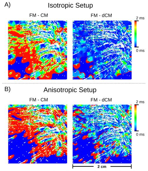
Postshock polarization patterns predicted by the dFE method were compared against the reference solution computed at the fine FM grid and the standard solution computed with the continuous FE method on the CM grid. Fig. 6 presents the spatial distribution of Vm and Φe for all three scenarios 0.5 and 1.5 ms post-shock. Figs. 6A) and B) show results for isotropic conductivity settings in which case all observed differences are attributable to the presence or absence of fine-scale discontinuities, but not to differences in fiber orientations. While there were minor visible deviations between FM and dCM case, a qualitative visual comparison against the standard CM case reveals that the dFE method captures structure-induced polarizations more accurately than the standard FE approach, with the solution being much closer to high-resolution reference simulation. In the CM simulation many fine-scale discontinuities which were explicitly represented in the FM case, were absent. Thus virtual electrode polarizations were induced to a much lesser degree which was particularly striking in the lower left quadrant of the domain (Fig. 6A) and C). Hence, no wavefront propagation was initiated there, thus leading to a noticeable activation delay in this region. This is illustrated in the activation maps in Fig. 7A) which present the spatial distribution of differences in local activation times relative to the reference FM case. Mean activation time errors and standard deviations were 1.37±1.11 ms and 0.35±0.69 ms in the isotropic CM and dCM cases, respectively.
Fig. 7.
Spatial distribution of the activation time errors for the transmembrane potential, when using the isotropic (A) and anisotropic (B) setups. Results are shown for CM and dCM relative to FM.
In the anisotropic case additional deviations emerged due to differences in fiber orientation between FM and dCM grid which influenced the formation of virtual electrode polarizations. This is apparent when comparing polarization patterns in FM/dCM panels between Fig. 6A) and C) or activation time errors between Fig. 7A) and B). Nonetheless, the overall distribution of Vm and Φe achieved with the dFE method approximates the solution obtained with the high resolution FM significantly better than in the standard CM case, as evidenced by comparing the CM and dCM panels in Fig. 6C) and D), albeit the match is not as close as in the isotropic case. In the anisotropic case mean activation time errors and standard deviations were 1.40±1.3 ms and 0.63±1.03 ms, respectively.
B. Computational Costs
The reduction in terms of nodes in the coarser CM and dCM meshes relative to the FM mesh translated into significant savings in execution times. As shown in Table I, when running on a single core simulation using the coarse CM mesh executed 158.9× faster than the corresponding run which used the FM mesh. Such speedups are within the range expected due to the reduction in workload by a factor of ~ 100. Comparable reductions in execution time (126.1×) were measured with the dFE method on the coarse dCM mesh, with speedups being slightly smaller than in the CM case, due to the marginally higher workload imposed by additional 18377 nodes. While the overall speedups decreased slightly when increasing the number of compute cores, n, even with n =16 reductions in execution time were significant. Solving the FM problem within similar time frames as the dCM problem would necessitate engaging a much larger number of cores, in the range n > 1000.
TABLE I.
Summary of execution times (T) and speedups (S) for solving the total system using fine mesh (FM), coarse mesh (CM) and decoupled coarse mesh (dCM). In terms of mesh nodes the CM and dCM meshes were 99.1 × and 68.1 × smaller than the FM mesh, respectively. n is the number of compute cores used.
| n |
TFM
[secs] |
TCM
[secs] |
SCM
[] |
TdCM
[secs] |
SdCM
[] |
|---|---|---|---|---|---|
|
| |||||
| 1 | 26501.0 | 166.7 | 158.9 | 210.2 | 126.1 |
| 4 | 10381.9 | 51.1 | 203.2 | 67.5 | 153.8 |
| 8 | 5285.5 | 28.6 | 184.8 | 33.5 | 157.7 |
| 16 | 3195.3 | 18.5 | 172.7 | 21.5 | 148.6 |
IV. Discussion
In this study a novel discontinuous FE approach for modeling fine-scale structural discontinuities in cardiac bidomain simulations has been developed. The method accounts for the presence of insulating micro-structures, as they arise in the aging myocardium or under pathologies such as fibrosis, without increasing the mesh resolution to spatially resolve these structures explicitly. Instead, electrical insulation due to such structures arising at size scales below a given spatial resolution are accounted for by a nodal splitting approach which imposes no-flux boundary conditions on intracellular current density and allows for discontinuities in intracellular potential, ϕi, while keeping the extracellular domain continuous. Simulation results demonstrate that the dFE method reduces computational costs significantly, by about two orders of magnitude. Qualitatively, relevant mechanisms such as virtual electrode formation around insulating obstacles, the subsequent initiation of wavefronts and their fractionation when encountering with such barriers, are captured faithfully. Quantitative comparison revealed only very minor differences relative to significantly more expensive simulation performed in a matching high-resolution mesh. The proposed method can be implemented in any continuous FE bidomain code with very minor effort which is a major advantage from a practical point of view. This additional flexibility renders the dFE method highly suitable for being used in modeling studies which seek to investigate bioelectric phenomena related to myocardial tissue structure at a microscopic size scale in the context of whole organ simulations.
A. Shock-induced polarizations and activation patterns
In the process of aging or in diseased hearts active myocytes are being replaced by connective tissue which invades spaces between myocytes, thus interrupting the intracellular matrix. Current flux between myocytes situated at opposite sites of fibrotic lesions, no matter how thin they are, is prevented, which renders the intracellular space discontinuous along such fracture lines. Such discontinuities may not show any noticeable manifestations at a macroscopic size scale and, therefore, their presence is most often fully ignored in computer models. However, there are various important scenarios in which micro-scale fibrotic lesions show prominent effects which are not limited to minor modulation of local behavior in the vicinity of the lesion, but influence behavior at the tissue and organ scale.
One such important effect is the induction of virtual electrode polarizations when external electric fields are applied [4]. Virtual electrodes form around such discontinuities which may initiate propagating wavelets after the break of a shock. There is mounting evidence that this mechanism plays a crucial role in success and failure of defibrillation shocks [16], [17] in addition to other mechanisms which are driven by continuous macroscopic size scale factors such as fiber rotation [18] or unequal anisotropy ratios [2]. It has been shown that a critical minimum size is required for such structures to elicit propagated responses [17], [19]. However, even lesions which are thin in width and well below a critical size, if their spatial extent in the longitudinal direction is sufficient as it is the case with fibrotic textures classified as patchy fibrosis [20], they constitute an important substrate for eliciting shock-induced propagated responses which clearly influence the outcome of defibrillation shocks.
Moreover, fibrosis does not only manifest during stimulation with electric fields, it has a profound impact upon activation patterns. Again, elongated lesions provide a substrate which structurally constrains conduction pathways through which electrical activation wave fronts stumble following complex zig-zag patterns. At a macroscopic size scale, these altered micro-propagation patterns may not be noticeable, but they manifest as apparent conduction slowing, an important factor known to promote arrhythmias by shortening the effective wavelength [21]. However, wavefront fractionation due to microscopic lesions may manifest at a macroscopic size scale depending on the incidence direction of wavefronts. Under incidence directions in parallel to a lesion electrogram fractionation at a given observation site may be negligible, however, large conduction delays between depolarization events may arise at the same observation site which are reflected as electrogram fractionation in the extracellular space, if incidence direction is orthogonal to the prevailing direction of fibrotic lesions [5].
The dFE method accounts for these effects in a computationally efficient manner. As illustrated in Fig. 6A) and B), virtual electrode polarization patterns were very similar between the FM and dCM case while computations were 126× to 203× less costly. In the standard CM case, many virtual electrode polarizations were missing, particularly in the lower left quadrant, which had a profound impact upon post-shock evolution. The post-shock excitable gap was much larger in this case and the total activation time needed to depolarize the tissue sheet was significantly prolonged. This was also reflected in a much closer match in local activation times between dCM and FM as compared to the CM case (Fig. 7A) and B).
In the isotropic case differences arose due to the imperfect approximation of fracture lines (Fig. 4B). Including anisotropy gave rise to additional deviations as a consequence of extracting fiber orientations from low resolution images. Induced polarizations depend on the angle between lesion and fiber orientation [18]. In the high resolution FM case there is a fine-grained variation in fiber angle along a lesion which is much coarser in the dCM case, thus leading to differences in average angle between dCM and FM. Despite these additional uncertainties, dCM results match the FM case much closer than the standard CM results.
B. Discontinuous FE method versus high resolution models
In recent years major advances in imaging technology [22] alongside with other factors such as a massive increase in available compute power [23], [24], [25], significant advancements in numerical methods for solving the bidomain equations [13] and image-based mesh generation techniques to spatially discretize complex geometries [26], [27] led to an increased interest in using anatomically highly accurate tomographic reconstructions of individual hearts [6], [7]. In ex-vivo MRI scans ultra-high spatial resolutions of around ≈ 25 μm can be achieved [22] which allow to identify fine structures at a paracellular size scale. Histological images such as used in this study provide even higher resolution and more structural detail, but typically these techniques are vastly time consuming, destructive and susceptible to artifacts [6] which limits their application to smaller tissue samples [28]. Models using such high spatial resolutions are feasible and have been employed to study the role of micro-structure in the formation of virtual electrode polarizations, and in electrogram fractionation, however, these studies have been limited to simpler model geometries such as 2D sheets [17], thin ventricular or atrial slices [19], [5] or small transmural wedge preparations [29]. While using such simplified model geometries can be insightful under many circumstances, mechanisms which govern success and failure of defibrillation therapy or formation and maintenance of arrhythmias can only be fully appreciated at the organ scale since factors such as biventricular geometry, structure of the endocardium, tissue orthotropy, specialized conduction system, physiological differences between right and left chambers as well as the presence of transmural, apicobasal and regional heterogeneities are known to be implicated in the underlying processes.
With current technology organ scale simulations at such ultra-high resolutions < 25 μm which could explicitly resolve mezo-scale structures as modeled in this study with the dFE method, are not feasible yet, however, such simulations may become feasible over the next decade. Further methodological advances will enable research to take advantage of massively parallel high performance computers to deal with workloads imposed by problem sizes of several tens to hundreds of million of unknowns. However, even in such scenarios discontinuous FE methods such as dFE may be of great utility. Not only execution times alone, also handling the overall amount of data generated, the computational costs of post-processing and visualization remain to be expensive. Further, using high resolutions in areas devoid of any mezo-scale structures may not be warranted. Therefore, it is common to reduce image resolution prior to mesh generation down to h ≈ 100 μm. Such paracellular resolutions at length of a single myocyte seem to be a viable trade-off between compute cost and anatomical detail. Models at this spatial discretization resolve the physics of the bidomain equations with high numerical accuracy and allow fast simulation and analysis cycles, the sweeping of large parameters spaces, or performing simulations on cheaper hardware. However, valuable information on the cardiac micro-structure, available at full resolution, is lost in the decimation process and, thus, its effects cannot be studied in the resulting model. While this may be negligible in many cases, particularly when macroscopic phenomena are under consideration, there are many problems of high practical relevance in which accounting for the myocardial micro-structure may be crucial.
The strength of the proposed dFE is its ability to account for the presence of microscopic structures which are at size scales below a chosen spatial resolution without any increase in computational costs. While the dFE method cannot achieve an identical match with the high resolution model, the observed differences are only marginal – particularly when viewed in context of uncertainties model parameters are afflicted with – and the savings in computational costs are vast. The main limitiation is rather image processing and representation as a skeleton. Any inaccuracies in these pre-processing steps will introduce errors in the simulations. Any missing skeleton representation of a fibrotic structure cannot cause a secondary source during field stimulation. Therefore, activation patterns in this regions will locally differ from the high resolution model. However, this is a limitation of the pre-processing methods only, not of the dFE method itself.
C. Comparison with previous studies and other techniques
In a previous study [30], the basic principle of using the dFE method for modeling fibrotic cleft spaces has been outlined for a simpler monodomain formulation. This concept has been applied successfully in subsequent studies for this very purpose [31]. The current work extends this idea by generalizing the dFE method to render it suitable for being used with a full bidomain formulation. In this case, the two spaces - intracellular and interstitial space - are treated differently. Only the intracellular space is decoupled, but not the interstitial space. Thus, there is no 1:1 relationship anymore between FE nodes in the two domains, requiring a more elaborate mapping procedure when exchanging data between the two interpenetrating grids. Further, in contrast to other previous studies, detailed simulations were performed to quantitatively assess potential deviations relative to the computationally more expensive standard method which relies upon high resolution meshes. As a benchmark a simulation setup has been chosen which aims at modeling microscopic size scale virtual electrode polarizations induced by electric field stimulation. In such a scenario the use of a full bidomain formulation is mandatory and the induced polarization patterns are highly sensitive to the presence fibrotic cleft spaces. In addition, the polarization patterns are also highly sensitive to fiber orientation and anisotropy. Therefore, in this study an anisotropic setup, which includes fiber orientation, is quantitatively compared against an isotropic setup.
Various methods for modeling of cracks using continuum finite element discretizations have been developed for a variety of applications in other fields of research. Similar approaches which rely upon nodal renumbering, as proposed in this study, have been used in other application such as e.g. [32] and [33]. While the proposed method bears similarities with other approaches, the way it is applied in this study is novel and unique due to the specific requirements imposed by the bidomain models where two spaces interpenetrate and isolation has to be enforced only in one of them.
Trew and co-workers developed a finite volume method for modeling discontinuities in cardiac tissue which would be applicable to the problem described in here as well [34]. They argued that the FVM paradigm has an distinct advantage over FE formulations in that planes of intracellular disruption can be represented without an implicit gain of extracellular volume. Their rationale was based on previous studies by Hooks et al. in which a FE formulation was used [28]. The gain of volume resulted from the fact that their standard FE formulation represented cleavage planes as volumetric elements so that the width of planes could not be smaller than the mesh resolution. While their argument is correct, the dFE method overcomes this very difficulty and allows to model cleavage planes of infinite thinness the same way as their FVM approach. Considering that a large percentage of currently used bidomain solver codes relies on FE discretizations a key advantage of our dFE method lies in that the cost of extending an existing continuous FE bidomain code to support modeling of fine-scale discontinuities is very minor.
Whether to use the dFE method or the FVM based method due to Trew et al. [34] is a question of preference, technically both methods achieve the same goal. The pre-processing task of identifying zero-flux faces is the same with both methods with the minor difference that in the dFE case the no-flux conditions are controlled on a per nodal basis and not over entire element faces. The FVM allows imposing no-flux conditions across faces in a mesh in a somewhat more natural way. With the dFE method the number of unknowns increases due to nodal splitting which increases the overall system size. However, in the most widely used scenario which relies on tetrahedral elements for spatial discretization, the dFE method may result in much smaller system sizes than the FVM since the sought after unknowns are potentials at element nodes and not potentials at element centers as it is the case with the FVM developed by Trew et al. [34]. Thus, the overall number of unknowns in this particular FVM scenario may be significantly higher, by about a factor of 5.
D. Extension to 3D
For the sake of elucidating the basic principle of the dFE method in a bidomain context 2D grids were used in this study, however, the method extends naturally to 3D without any further modifications. A simplified monodomain version of the dFE method has been employed already in a previous study which investigated the role of fibrosis in the formation and maintenance of arrhythmias in a 3D model of the human atria [31]. In contrast to this study, bidomain effects were neglected and discontinuities in the fibrotic substrate were represented in a statistical sense. Thus the additional complexity of intersecting fracture lines or surfaces with a pre-existing FE mesh and the projection operations between intracellular and extracellular grid were not required.
As in the 2D scenario, in 3D the only information needed is on the elements marked for splitting, and the subset of nodes in these elements to be split, but neither dimensionality nor type of element matter. The more challenging problem are the pre-processing algorithms which generate the splitting information. To be of wider applicability all steps in the pipeline which include segmentation, mesh generation, finding discrete representation of discontinuities and intersecting them with the previously generated mesh have to be executed in an almost fully automatic fashion, as it is the case for the 2D method presented in this study. The critical difficulties in a generic 3D scenario are to find discrete representations of the discontinuous planes and to intersect these planes with a fully unstructured grid. While this can be addressed in 2D by skeletonization of fracture lines, analog skeletonization methods applicable in 3D are not readily available.
In previous studies [28] fracture planes were identified manually and represented by bilinear finite elements. While this is a feasible approach for a small number of samples, for high throughput modeling studies it would be prohibitive. Moreover, these discrete representations were projected onto structured grids without attempts to remesh to accommodate discontinuities as smoothly as possible [34]. Thus fracture planes are represented as jagged surfaces which may cause spurious polarizations when applying external electric field, since, unlike with unstructured grids which smoothly accommodate organ surfaces, fiber orientations cannot be aligned in parallel to the organ surface. This is a well known artefact in defibrillation studies which represent complex geometries with structured voxel-based grids.
Ideally, accounting for fine-scale discontinuities is integrated in the mesh generation process to obtain smooth boundary-fitted representations. However, image-based mesh generation of complex structures such as organ-scale heart models at a paracellular resolution is a highly challenging problem in its own right [26], [27]. To our knowledge, there are currently no mesh generation methods available which would be able to deal with this added complexity.
In the near future, we aim at extending the method presented in this study to a 3D scenario by first developing an analog representation of the skeleton in 3D using the available image processing technology. To our understanding, as the 3D data sets typically consist of 2D image stacks, the 3D problem could be treated as a set of pseudo 2D problems, that can later on be combined to construct a complete 3D representation of the discontinuous structures. Moreover, extending the procedure used in this study to search for intersections between the discontinuous structures and the previously generated mesh to a 3D scenario should be straightforward, with intersections now occuring between tridimensional planes instead of lines.
V. Conclusions
In this study a novel computationally efficient discontinuous FE method is presented which allows to account for effects due to uncoupling structures in cardiac tissue upon wavefront propagation and field-induced polarization patterns on a coarser computational grid, without the need to use high resolution meshes to spatially resolve these structures explicitly. Comparison between computationally expensive high-resolution bidomain simulations and the novel dFE method used on coarser grids demonstrated that an excellent qualitative and quantitative match could be achieved at a fraction of the computational costs.
Acknowledgments
This work was supported by the grants P19993-N15 and SFB F3210-N18 from the Austrian Science Fund (FWF), NIH 1RO1 HL 10119601, SIMNET Styria as well as by FAPEMIG-Brazil.
Biography
Caroline Mendonca-Costa received the B.Sc. degree in Computer Science from the Federal University of Juiz de Fora (UFJF), Brazil, in 2009 and the M.Sc. degree in Computational Modeling from the UFJF in 2011. She is currently a PhD student at the Institute of Mathematics and Scientific Computing, University of Graz, Graz, Austria, and Research Assistant at the Institute of Biophysics, Medical University of Graz, Austria. Her research interests include methodological and applied aspects of computational modeling of cardiac electrophysiology, with emphasis on the role of tissue microstructure and model parametrization.
Fernando O. Campos received the B.Sc. degree in Informatics from the Federal University of Juiz de Fora (UFJF), Brazil, in 2005; the M.Sc. degree in Computational Modeling from UFJF in 2008; and the Ph.D. degree from the Graz University of Technology, Graz, Austria, in 2012. He is currently a Postdoctoral Fellow at the Institute of Biophysics, Medical University of Graz, Graz, Austria. He is a member of the Austrian Society for Biomedical Engineering. His research interests include computational modeling of the electrical activity in the heart, with emphasis on the role of tissue microstructure and triggered activity on arrhythmogenesis.
Anton J. Prassl received the M.Sc. and Ph.D. degrees in electrical engineering from the Institute of Biomedical Engineering, Graz University of Technology, Graz, Austria, in 2003 and 2008, respectively. He is currently a Postdoctoral Fellow at the Institute of Biophysics, Medical University of Graz, Graz. During 2006-2007, he was a Research Scholar at the Johns Hopkins University. His research interests include computational modeling of electrical and mechanical activity of the heart.

Rodrigo Weber dos Santos received the B.Sc. in electrical engineering from the Federal University of Rio de Janeiro (UFRJ), Brazil, in 1995; the M.Sc. from UFRJ, Computer and Systems Engineering, in 1998; and the D.Sc. from UFRJ, Mathematics Department, in 2002. Currently he is an Associate Professor with the Dept. of Computer Science of the Federal University of Juiz de Fora, Brazil and with the Graduate Program in Computational Modelling. Prior to this, he was a Research Fellow with the Dept. of Biosignals, PTB, Berlin, Germany (2002-2004); and with CERN, Geneva, Switzerland (1995-1996). His research interests include parallel computing, numerical methods for PDEs and mathematical and computational modelling of the heart.

Damián Sánchez-Quintana received MD and Ph.D. degrees in medicine from the University of Extremadura, Badajoz, Spain, in 1979 and 1986, respectively. He is currently Professor of Human Anatomy at the Faculty of Medicine of Badajoz. In 1995 he was a senior visitor at the laboratory of Professor Robert H. Anderson, in the Department of Paediatrics, National Heart and Lung Institute, London. Since 1996 he is dedicated to the study of the macroscopic and microscopic structure of morphologic substrates underlying different arrhythmias in different areas of the heart such as triangle of Koch, cavo-tricuspid isthmus, cardiac nodes and their vascularization, left atrium and pulmonary veins.

Helmut Ahammer received the M.Sc. and Ph.D. degree in experimental physics from the University of Graz, Graz, Austria, in 1990 and 1996, respectively. He is currently an Associate Professor of Medical Physics and Biophysics at the Institute of Biophysics, Medical University of Graz, Graz, where he is involved in the field of image processing and quantitative image analysis. His current research interests include fractals, nonlinear methods, and quantitative methods in order to analyze digital images of biological objects.

Ernst Hofer received the M.Sc.(‘77) and Ph.D. (‘85) degrees in electrical engineering from the Technical University of Graz, Graz, Austria. From 1985 to 1990, he was an Assistant Professor at the Karl-Franzens-University Graz, Graz. Since 1990, he has been an Associate Professor of Medical Physics and Biophysics in the Department of Biophysics, Medical University of Graz, Graz. His current research interests include development of scientific instruments and measurement systems for cardiac electrophysiology, specifically for measurement and analysis of microscopic excitation spread in cardiac tissue. He is currently the vice-president of the Austrian Society for Biomedical Engineering.

Gernot Plank received the M.Sc. (‘96) and Ph.D. (‘00) degrees in electrical engineering from the Technical University of Graz (TUG), Austria. Currently he is Associate Professor with the Institute of Biophysics, Medical University of Graz, Austria and Academic Fellow with the Oxford e-Research Centre, University of Oxford, UK. Prior, he was a Postdoctoral Fellow with the Technical University of Valencia, Spain (‘00–‘02), the University of Calgary, AB, Canada (‘03) and Marie Curie Fellow with Johns Hopkins University (‘06–‘08). His research interests include methodological and applied aspects of computational modelling of cardiac electrophysiology and mechanics.
Contributor Information
Caroline Mendonca Costa, Institute of Biophysics, Medical University of Graz, Harrachgasse 21/IV, A-8010 Graz, Austria.
Fernando O. Campos, Institute of Biophysics, Medical University of Graz, Harrachgasse 21/IV, A-8010 Graz, Austria
Anton J. Prassl, Institute of Biophysics, Medical University of Graz, Harrachgasse 21/IV, A-8010 Graz, Austria
Rodrigo Weber dos Santos, Graduate Program on Computational Modeling, Universidade Federal de Juiz de Fora, Campus Universitário, 36036-330 Juiz de Fora - MG, Brazil. rodrigo.weber@ufjf.edu.br.
Damián Sánchez-Quintana, Departamento de Anatomía, Biología Celular y Zoología, Universidad de Extremadura, Avenida de la Universidad, 10003 Caceres, Spain. damians@unex.es.
Helmut Ahammer, Institute of Biophysics, Medical University of Graz, Harrachgasse 21/IV, A-8010 Graz, Austria.
Ernst Hofer, Institute of Biophysics, Medical University of Graz, Harrachgasse 21/IV, A-8010 Graz, Austria.
Gernot Plank, Institute of Biophysics, Medical University of Graz, Harrachgasse 21/IV, A-8010 Graz, Austria. gernot.plank@medunigraz.at.
REFERENCES
- [1].Miller WT, Geselowitz DB. Simulation studies of the electrocardiogram. i. the normal heart. Circ Res. 1978 Aug;43(2):301–315. doi: 10.1161/01.res.43.2.301. [DOI] [PubMed] [Google Scholar]
- [2].Sepulveda NG, Roth BJ, Wikswo J., Jr Current injection into a two-dimensional anisotropic bidomain. Biophys J. 1989 May;55(5):987–999. doi: 10.1016/S0006-3495(89)82897-8. [Online]. Available: http://dx.doi.org/10.1016/S0006-3495(89)82897-8. [DOI] [PMC free article] [PubMed] [Google Scholar]
- [3].Spach MS. The discontinuous nature of electrical propagation in cardiac muscle. Consideration of a quantitative model incorporating the membrane ionic properties and structural complexities. The ALZA distinguished lecture. Ann Biomed Eng. 1983;11(3-4):209–61. doi: 10.1007/BF02363287. [DOI] [PubMed] [Google Scholar]
- [4].Fast VG, Rohr S, Gillis AM, Kléber AG. Activation of cardiac tissue by extracellular electrical shocks: formation of ‘secondary sources’ at intercellular clefts in monolayers of cultured myocytes. Circ Res. 1998 Feb;82(3):375–385. doi: 10.1161/01.res.82.3.375. [DOI] [PubMed] [Google Scholar]
- [5].Campos F, Wiener T, Prassl A, dos Santos RW>, Sanchez-Quintana D, Ahammer H, Plank G, Hofer E. Electro-anatomical characterization of atrial microfibrosis in a histologically detailed computer model. IEEE Trans Biomed Eng. 2013 Aug;60:2339–2349. doi: 10.1109/TBME.2013.2256359. [Online]. Available: http://dx.doi.org/10.1109/TBME.2013.2256359. [DOI] [PMC free article] [PubMed] [Google Scholar]
- [6].Plank G, Burton RA, Hales P, Bishop M, Mansoori T, Bernabeu MO, Garny A, Prassl AJ, Bollensdorff C, Mason F, Mahmood F, Rodriguez B, Grau V, Schneider JE, Gavaghan D, Kohl P. Generation of histo-anatomically representative models of the individual heart: tools and application. Philos Trans A Math Phys Eng Sci. 2009;367(1896):2257–92. doi: 10.1098/rsta.2009.0056. [DOI] [PMC free article] [PubMed] [Google Scholar]
- [7].Bishop MJ, Plank G, Burton RAB, Schneider JE, Gavaghan DJ, Grau V, Kohl P. Development of an anatomically detailed mri-derived rabbit ventricular model and assessment of its impact on simulations of electrophysiological function. Am J Physiol Heart Circ Physiol. 298(2):H699–H718. doi: 10.1152/ajpheart.00606.2009. http://dx.doi.org/10.1152/ajpheart.00606.2009 [DOI] [PMC free article] [PubMed] [Google Scholar]
- [8].Karlon WJ, Covell JW, McCulloch AD, Hunter JJ, Omens JH. Automated measurement of myofiber disarray in transgenic mice with ventricular expression of ras. Anat Rec. 1998;252(4):612–25. doi: 10.1002/(SICI)1097-0185(199812)252:4<612::AID-AR12>3.0.CO;2-1. [DOI] [PubMed] [Google Scholar]
- [9].Weber dos Santos R, Steinhoff U, Hofer E, Sánchez-Quintana D, Koch H. Modelling the electrical propagation in cardiac tissue using detailed histological data. Biomedizinische Technik. Biomedical Engineering. 2003;48:476–479. [Google Scholar]
- [10].Bishop M, Plank G, Vigmond E. Investigating the role of the coronary vasculature in the mechanisms of defibrillationclinical perspective. Circ Arrhythm Electrophysiol. 2012;5:210–219. doi: 10.1161/CIRCEP.111.965095. [DOI] [PMC free article] [PubMed] [Google Scholar]
- [11].Skouibine K, Trayanova N, Moore P. Anode/cathode make and break phenomena in a model of defibrillation. IEEE Trans Biomed Eng. 1999;46(7):769–777. doi: 10.1109/10.771186. [DOI] [PubMed] [Google Scholar]
- [12].Vigmond E, Hughes M, Plank G, Joshua Leon L. Computational tools for modeling electrical activity in cardiac tissue. Journal of Electrocardiology. 2003;36 doi: 10.1016/j.jelectrocard.2003.09.017. [DOI] [PubMed] [Google Scholar]
- [13].Plank G, Liebmann M, Weber dos Santos R, Vigmond EJ, Haase G. Algebraic multigrid preconditioner for the cardiac bidomain model. IEEE Trans Biomed Eng. 2007 Apr;54(4):585–96. doi: 10.1109/TBME.2006.889181. [DOI] [PMC free article] [PubMed] [Google Scholar]
- [14].Vigmond EJ, Weber dos Santos R, Prassl AJ, Deo M, Plank G. Solvers for the cardiac bidomain equations. Prog. Biophys. Mol. Biol. 2008;96(1-3):3–18. doi: 10.1016/j.pbiomolbio.2007.07.012. [DOI] [PMC free article] [PubMed] [Google Scholar]
- [15].Plank G, Zhou L, Greenstein JL, Cortassa S, Winslow RL, O’Rourke B, Trayanova NA. From mitochondrial ion channels to arrhythmias in the heart: computational techniques to bridge the spatio-temporal scales. Philos Trans A Math Phys Eng Sci. 2008 Sep;366(1879):3381–3409. doi: 10.1098/rsta.2008.0112. [Online]. Available: http://dx.doi.org/10.1098/rsta.2008.0112. [DOI] [PMC free article] [PubMed] [Google Scholar]
- [16].Fenton FH, Luther S, Cherry EM, Otani NF, Krinsky V, Pumir A, Bodenschatz E, Gilmour RF., Jr Termination of atrial fibrillation using pulsed low-energy far-field stimulation. Circulation. 2009 Aug;120(6):467–476. doi: 10.1161/CIRCULATIONAHA.108.825091. [Online]. Available: http://dx.doi.org/10.1161/CIRCULATIONAHA.108.825091. [DOI] [PMC free article] [PubMed] [Google Scholar]
- [17].Luther S, Fenton FH, Kornreich BG, Squires A, Bittihn P, Hornung D, Zabel M, Flanders J, Gladuli A, Campoy L, Cherry EM, Luther G, Hasenfuss G, Krinsky VI, Pumir A, Gilmour RF, Jr, Bodenschatz E. Low-energy control of electrical turbulence in the heart. Nature. 2011 Jul;475(7355):235–239. doi: 10.1038/nature10216. [Online]. Available: http://dx.doi.org/10.1038/nature10216. [DOI] [PMC free article] [PubMed] [Google Scholar]
- [18].Plank G, Prassl A, Hofer E, Trayanova NA. Evaluating intramural virtual electrodes in the myocardial wedge preparation: simulations of experimental conditions. Biophys J. 2008 Mar;94(5):1904–1915. doi: 10.1529/biophysj.107.121343. [Online]. Available: http://dx.doi.org/10.1529/biophysj.107.121343. [DOI] [PMC free article] [PubMed] [Google Scholar]
- [19].Bishop MJ, Plank G, Vigmond E. Investigating the role of the coronary vasculature in the mechanisms of defibrillation. Circ Arrhythm Electrophysiol. 2012 Feb;5(1):210–219. doi: 10.1161/CIRCEP.111.965095. [Online]. Available: http://dx.doi.org/10.1161/CIRCEP.111.965095. [DOI] [PMC free article] [PubMed] [Google Scholar]
- [20].de Jong S, van Veen TAB, van Rijen HVM, de Bakker JMT. Fibrosis and cardiac arrhythmias. J Cardiovasc Pharmacol. 2011 Jun;57(6):630–638. doi: 10.1097/FJC.0b013e318207a35f. [Online]. Available: http://dx.doi.org/10.1097/FJC.0b013e318207a35f. [DOI] [PubMed] [Google Scholar]
- [21].Rensma PL, Allessie MA, Lammers WJ, Bonke FI, Schalij MJ. Length of excitation wave and susceptibility to reentrant atrial arrhythmias in normal conscious dogs. Circ Res. 1988;62(2):395–410. doi: 10.1161/01.res.62.2.395. [DOI] [PubMed] [Google Scholar]
- [22].Schneider JE, Böse J, Bamforth SD, Gruber AD, Broadbent C, Clarke K, Neubauer S, Lengeling A, Bhattacharya S. Identification of cardiac malformations in mice lacking ptdsr using a novel high-throughput magnetic resonance imaging technique. BMC Dev Biol. 2004;4:16. doi: 10.1186/1471-213X-4-16. [Online]. Available: http://dx.doi.org/10.1186/1471-213X-4-16. [DOI] [PMC free article] [PubMed] [Google Scholar]
- [23].Niederer S, Mitchell L, Smith N, Plank G. Simulating human cardiac electrophysiology on clinical time-scales. Front Physiol. 2011;2:14. doi: 10.3389/fphys.2011.00014. [Online]. Available: http://dx.doi.org/10.3389/fphys.2011.00014. [DOI] [PMC free article] [PubMed] [Google Scholar]
- [24].Neic A, Liebmann M, Hoetzl E, Mitchell L, Vigmond EJ, Haase G, Plank G. Accelerating cardiac bidomain simulations using graphics processing units. IEEE Trans Biomed Eng. 2012 Aug;59(8):2281–2290. doi: 10.1109/TBME.2012.2202661. [Online]. Available: http://dx.doi.org/10.1109/TBME.2012.2202661. [DOI] [PMC free article] [PubMed] [Google Scholar]
- [25].Richards DF, Glosli JN, Draeger EW, Mirin AA, Chan B, Fattebert J-L, Krauss WD, Oppelstrup T, Butler CJ, Gunnels JA, Gurev V, Kim C, Magerlein J, Reumann M, Wen H-F, Rice JJ. Towards real-time simulation of cardiac electrophysiology in a human heart at high resolution. Comput Methods Biomech Biomed Engin. 2013 Jun; doi: 10.1080/10255842.2013.795556. [Online]. Available: http://dx.doi.org/10.1080/10255842.2013.795556. [DOI] [PubMed] [Google Scholar]
- [26].Prassl AJ, Kickinger F, Ahammer H, Grau V, Schneider JE, Hofer E, Vigmond EJ, Trayanova NA, Plank G. Automatically generated, anatomically accurate meshes for cardiac electrophysiology problems. IEEE Trans Biomed Eng. 2009 May;56(5):1318–1330. doi: 10.1109/TBME.2009.2014243. [Online]. Available: http://dx.doi.org/10.1109/TBME.2009.2014243. [DOI] [PMC free article] [PubMed] [Google Scholar]
- [27].S. Institute . bioMesh3D: Quality Mesh Generator for Biomedical Applications. Scientific Computing and Imaging Institute (SCI); 2013. [Online]. Available: http://www.biomesh3d.org. [Google Scholar]
- [28].Hooks AD, Tomlinson AK, Marsden GS, LeGrice IJ, Smaill BH, Pullan AJ, Hunter PJ. Cardiac microstructure: implications for electrical propagation and defibrillation in the heart. Circulation Research. 2002;91:331–338. doi: 10.1161/01.res.0000031957.70034.89. [DOI] [PubMed] [Google Scholar]
- [29].Hooks DA, Trew ML, Smaill BH, Pullan AJ. Do intramural virtual electrodes facilitate successful defibrillation? model-based analysis of experimental evidence. J Cardiovasc Electrophysiol. 2006 Mar;17(3):305–311. doi: 10.1111/j.1540-8167.2006.00360.x. [Online]. Available: http://dx.doi.org/10.1111/j.1540-8167.2006.00360.x. [DOI] [PubMed] [Google Scholar]
- [30].Mendonca Costa C, Campos FO, Prassl AJ, dos Santos RW, Sanchez-Quintana D, Hofer E, Plank G. A finite element approach for modeling micro-structural discontinuities in the heart; Conf Proc IEEE Eng Med Biol Soc; 2011. pp. 437–440. [DOI] [PMC free article] [PubMed] [Google Scholar]
- [31].McDowell K, Vadakkumpadan F, Blake R, Blauer J, Plank G, MacLeod R, Trayanova N. Mechanistic inquiry into the role of tissue remodeling in fibrotic lesions in human atrial fibrillation. Communications of the ACM. 2013;104(12) doi: 10.1016/j.bpj.2013.05.025. [DOI] [PMC free article] [PubMed] [Google Scholar]
- [32].Grillo A, Logashenko D, Stichel S, Wittum G. Simulation of density-driven flow in fractured porous media. Advances in Water Resources. 2010;33:1494–1507. [Google Scholar]
- [33].Moes T, Dolbow N, Belytschko J. A finite element method for crack growth without remeshing. Int. J. Numer. Meth. Engng. 1999;46:131–150. [Google Scholar]
- [34].Trew M, Le Grice I, Smaill B, Pullan A. A finite volume method for modeling discontinuous electrical activation in cardiac tissue. Ann Biomed Eng. 2005 May;33(5):590–602. doi: 10.1007/s10439-005-1434-6. [DOI] [PubMed] [Google Scholar]


