Abstract
Histotripsy produces tissue fractionation through dense energetic bubble clouds generated by short, high-pressure, ultrasound pulses. When using pulses shorter than 2 cycles, the generation of these energetic bubble clouds only depends on where the peak negative pressure (P–) exceeds an intrinsic threshold of a medium (26 – 30 MPa in soft tissue with high water content). This paper investigates a strategic method for precise lesion generation in which a low-frequency pump pulse is applied to enable a sub-threshold high-frequency probe pulse to exceed the intrinsic threshold. This pump-probe method of controlling a supra-threshold volume can be called “dual-beam histotripsy.” A 20-element dual-frequency (500 kHz and 3 MHz elements confocally aligned) array transducer was used to generate dual-beam histotripsy pulses in RBC phantoms and porcine hepatic tissue specimens. The results showed that, when sub-intrinsic-threshold pump (500 kHz) and probe (3 MHz) pulses were applied together, dense bubble clouds (and resulting lesions) were only generated when their peak negative pressures combined constructively to exceed the intrinsic threshold. The smallest reproducible lesion varied with the relative amplitude between the pump and probe pulses, and, with a higher proportion of the probe pulse, smaller lesions could be generated. When the propagation direction of the probe pulse relative to the pump pulse was altered, the shape of the produced lesion changed based on the region that exceeded intrinsic threshold. Since the low-frequency pump pulse is more immune to attenuation and aberrations, and the high-frequency probe pulse can provide precision in lesion formation, this dual-beam histotripsy approach would be very useful in situations where precise lesion formation is required through a highly attenuative and aberrative medium, such as transcranial therapy. This is particularly true if a small low-attenuation acoustic window is available for the high-frequency probe transducer.
Keywords: Dual-Beam Histotripsy, Pump-Probe, Microtripsy, Histotripsy Tissue Fractionation
I. INTRODUCTION
Histotripsy is a noninvasive, cavitation-based therapy that uses very short, high-pressure ultrasound pulses to generate a dense, energetic, lesion-producing bubble cloud. Histotripsy treatments can create controlled tissue erosion at a fluid-tissue interface [1-3], well-demarcated tissue fractionation within bulk tissue [4-6], and controlled fragmentation of model kidney stones at a fluid-stone interface [7, 8].
Conventional histotripsy uses ultrasound pulses longer than 3 cycles, in which the generation of bubble clouds relies on the pressure-release scattering of the positive shock fronts from initially initiated, sparsely distributed bubbles (the “shock scattering mechanism”) [9]. This shock scattering process changes with applied exposure conditions, making the threshold for bubble cloud generation variable and the spatial extent of the produced lesion somewhat unpredictable.
Our recent study showed that, when ultrasound pulses less than 2 cycles were applied, wherein shock scattering was minimized, the generation of a dense bubble cloud only depended on one or two negative half cycle(s) of the applied ultrasound pulses exceeding an “intrinsic threshold” of the medium (the “intrinsic threshold mechanism”) [10]. This threshold was found to be in the range of 26 – 30 MPa for soft tissues with high water content. Using this intrinsic threshold mechanism, the spatial extent of the lesion is well-defined and more predictable. With peak negative pressure (P–) not significantly higher than this threshold, sub-wavelength reproducible lesions as small as half of the –6dB beamwidth of the transducer could be generated (“microtripsy”) [11].
As shown in the study [11], with higher-frequency histotripsy pulses, the size of the smallest reproducible lesion becomes smaller, which is beneficial in applications that require precise lesion generation. However, higher frequency pulses are more susceptible to attenuation and aberration, rendering problematical treatments at a longer penetration depth or through a highly aberrative medium, e.g., transcranial procedures. In this paper, we propose a strategic application of histotripsy pulses to address this issue: a low-frequency pump pulse (< 2 cycles) is applied together with a high-frequency probe pulse (< 2 cycles) wherein their peak negative pressures constructively interfere to exceed the intrinsic threshold. The low-frequency pump, which is more resistant to attenuation and aberration, can raise the P– level for a region of interest (ROI); while the high-frequency probe (perhaps an imaging transducer), which provides more precision, can pin-point a targeted location within the ROI and raise the P– above the intrinsic threshold. We call this approach “dual-beam histotripsy.”
Previous studies from Umemura et al [12, 13] showed that the superimposition of the 2nd-harmonic onto the fundamental frequency can enhance cavitation activity. More specifically, Umemura et al [12] demonstrated that the superimposition of the 2nd-harmonic onto the fundamental frequency with two confocal transducers can enhance sonodynamic therapy wherein cavitation enhances the therapeutic effect of certain agents administered prior to treatment. Yoshizawa et al [13] studied the bubble cloud generation near a rigid wall by 2nd-harmonic superimposed ultrasound, and their results showed that the negative pressure emphasized wave had an advantage in cavitation inception over the positive pressure emphasized wave.
Several other studies have also investigated waveform manipulation methods to either enhance or reduce cavitation activity. The study conducted by Chapelon et al [14] showed that the sonoluminescence activity (using luminol as a cavitation detector) generated with pseudorandom phase-modulated signals was significantly lower than that generated with continuous-wave (CW), single-frequency ultrasound. Sokka et al [15] investigated the effect of dual-frequency driving waveforms on injected microbubbles both theoretically and experimentally, and the results showed that their developed dual-frequency methods could preferentially lower the cavitation threshold at the focus relative to the rest of the field. Matsumoto et al [16] and Ikeda et al [17, 18] utilized dual frequency excitation for cloud cavitation control in renal stone comminution, wherein the bubble cloud was firstly created by a high-frequency pulse and then forced into a violent collapse with a succeeding low-frequency pulse for fragmentation of kidney stones. Liu and Hsieh [19] generated dual-frequency ultrasound waves using a single-element transducer and demonstrated its capability in enhancing acoustic cavitation. Hasanzadeh et al [20] investigated the enhancement of acoustic cavitation generated on aluminum foil using dual-frequency sonication with transducers of several different frequencies.
The dual-beam histotripsy approach proposed in this paper is mechanistically different from the previous studies [12-20]. In the previous studies, longer pulses (>50 μs in [16-18], 125μs in [13], and CW for the rest) were used and the enhancement (or suppression) of acoustic cavitation was accomplished by pseudo-random phase-modulation, harmonic superimposition, and high frequency pulse followed by low frequency pulse, not necessarily increasing the applied pressure level using the 2nd frequency component. In contrast, dual-beam histotripsy uses pulses less than two cycles, and the arrival times of the pump and probe were adjusted to enhance P–constructive interference. Additionally, the cavitation probability was enhanced in the previous studies by microbubble seeding or reflection from a rigid interface (except for [14]), whereas dual-beam histotripsy generates a dense bubble cloud without any pre-existing microbubbles or special interfaces.
In this paper, the feasibility of dual-beam histotripsy was investigated using red-blood-cell (RBC) tissue-mimicking phantoms and ex vivo porcine livers. More specifically, a 20-element dual-frequency array transducer, in which 500 kHz (pump) and 3 MHz (probe) elements were confocally aligned, was used to generate dual-beam histotripsy pulses at a pulse repetition frequency (PRF) of 1 Hz. Three experimental sets were performed in RBC phantoms wherein: 1) the arrival times of 500 kHz and 3 MHz pulses (both below intrinsic threshold) were varied in order to investigate whether lesions could only be generated when combined P–values exceeded the intrinsic threshold, 2) the relative amplitude of 500 kHz and 3 MHz pulses was varied to study the size of the smallest reproducible lesion with different proportions of pump and probe, and 3) the relative propagation direction between 500 kHz and 3 MHz pulses was varied to determine the effect on the shape and size of the produced lesions. Finally, selected dual-beam histotripsy pulses were tested in ex vivo porcine hepatic specimens to validate the results in real tissue.
II. MATERIALS AND METHODS
A. Sample Preparation
Experiments were performed on red-blood-cell (RBC) tissue-mimicking phantoms and ex vivo porcine livers to investigate the treatment effect for the dual-beam histotripsy pulses. The procedures described in this study were approved by the University of Michigan's Committee on Use and Care of Animals.
The RBC tissue-mimicking phantoms can be used for the visualization and quantification of cavitation-induced damage [21]. In this study, fresh canine blood was obtained from adult research canine subjects in an unrelated study. An anticoagulant solution of citrate-phosphate-dextrose (CPD) (C7165, Sigma-Aldrich, St. Louis, MO, USA) was added to the blood with a CPD-to-blood ratio of 1:9 (v:v), and the blood was kept at 4°C and used within 3 weeks. A low-melting-point agarose powder (AG-SP, LabScientific, Livingston, NJ, USA) was used along with the canine blood to prepare RBC phantoms following the protocol described in [21]. In this study, since the expected lesions are very small (in the range of 200 - 500 μm), the central layer preparation differed slightly from the protocol. Instead of lying flat when the central layer was solidifying, the gel holder was mounted vertically such that the agarose-saline-RBC mixture trickled down the previous agarose-only casting while solidifying into a very thin central layer (~ 60 – 100 μm) [Fig. 1(a)]. Additionally, in order to provide sufficient image contrast between treated and untreated regions, the ratio of RBCs to agarose-saline mixture was increased from 5:95 to 33:67 (v:v). The gel holder for RBC phantoms is shown in Fig. 1(b).
Fig. 1.
(a) A bright field microscope image with a 10x objective showing the cross-section of a representative RBC phantom. The RBC phantom here was sectioned into a thin slice for microscope inspection. (b) A picture of a representative gel holder for RBC phantoms. (c) A picture of a representative holder for agarose-embedded porcine hepatic specimens.
Experiments were also performed in ex vivo porcine livers to validate the results observed in the RBC phantoms. The excised porcine livers were collected from a local abattoir, kept in 0.9% saline at 4°C, and used within 36 hours. Before the experiments, the livers were sectioned into small specimens (~2 × 2 × 2 cm), submerged in degassed 0.9% saline and placed in a chamber under partial vacuum (~33 kPa) at room temperature for 1 – 2 hours. The specimens were then embedded in a 1% agarose hydrogel that consisted of low-melting-point agarose and 0.9% saline. The gel holder for liver experiments is shown in Fig. 1(c).
B. Histotripsy Pulse Generation and Calibration
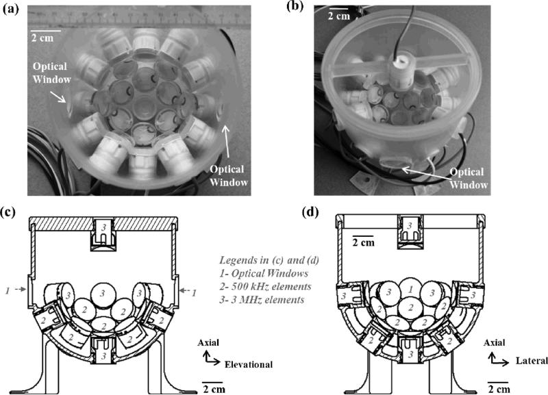
Histotripsy pulses were generated by a custom, 20-element, dual-frequency array transducer (Fig. 2) that consisted of twelve 500 kHz elements and eight 3 MHz elements. Each 500 kHz element consisted of two 1 MHz, 20-mm-diameter piezoceramic discs (PZ36, Ferroperm, Kvistgaard, Denmark) stacked together with epoxy, while each 3 MHz element consisted of a single 3 MHz, 20-mm-diameter piezoceramic disc (SM111, Steiner and Martins, Miami, FL, USA). Both 500 kHz and 3 MHz elements were individually mounted to acoustic lenses with a geometric focus of 40 mm. The elements were confocally aligned and arranged in the following order: 1) the very bottom of the array transducer – one 3 MHz element, 2) 1st ring from the bottom – six 500 kHz elements with a 37-degree tilt angle, 3) 2nd ring from the bottom – six 500 kHz elements with a 64-degree tilt angle, 4) 3rd ring from the bottom – six 3 MHz elements with a 85-degree tilt angle, and 5) on top of the array transducer – one 3MHz element that was attached to a supporting frame and had an opposite propagation direction, which was from top to bottom. This top element was used only during the study that investigated the effect of different propagation directions of the 3 MHz element relative to the 500 kHz component. Note that the 20-element dual frequency transducer actually had four additional elements above its third ring with 103-degree tilt angle [can be seen in Figs. 2(a) and (b)], but they were never used in this study. In drawings of the cross-sections [Figs. 2(c) and 2(d)], and following figures and calibration measurements, these four elements were excluded.
Fig. 2.
20-element dual-frequency array transducer (a) A top-down view of the transducer without the top element and adapting frame. (b) An angled view of the transducer with the top element and adapting frame. (c) A cross-sectional drawing of the transducer in the axial-elevational plane with the top element and adapting frame. (d) A cross-sectional drawing of the transducer in the axial-lateral plane with the top element and adapting frame. The axial direction of the transducer is defined as the vertical direction from the bottom to the top of the transducer. The lateral direction of the transducer is defined as the horizontal direction that is orthogonal to the direction of the two diametrically opposed optical windows. The elevational direction of the transducer is defined as the horizontal direction that is parallel to the direction of the two diametrically opposed optical windows. Note that, this array transducer actually has 24 elements; however, four elements above the 3rd ring were not used in this study. Therefore, in Figs. 2(c) – (d), 5, and 11(a1), (b1), and (c1), these four elements were not shown in the design.
Additionally, this dual-frequency array transducer also had two diametrically opposed optical windows, approximately at the same height as the 3rd ring and facing each other, for the visualization of the cavitating bubble clouds and lesions generated in RBC phantoms. To generate short therapy pulses, a custom high voltage pulser developed in-house was used to drive the transducer. The pulser was connected to a field-programmable gated array (FPGA) development board (Altera DE1, Terasic Technology, Dover, DE, USA) specifically programmed for histotripsy therapy pulsing. This setup allowed the transducer to output short pulses consisting of less than two cycles. The transducer was filled with degassed water (~50% of normal PO2) during experiments, and the gas saturation was measured by a commercial dissolved oxygen meter (YSI5000, YSI Inc., Yellow Springs, OH, USA).
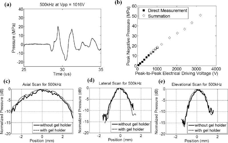
A fiber-optic probe hydrophone (FOPH) built in-house [22] was used to measure the acoustic output pressure of the dual-frequency transducer. Fig. 3 shows the calibration results of the 500 kHz component (a total of 12 elements) in free-field, including a representative focal pressure waveform before inducing cavitation on the FOPH [Fig. 3(a)], total focal P– as a function of peak-to-peak driving voltage [Fig. 3(b)], and one-dimensional (1D) beam profiles in the axial [Fig. 3(c)], lateral [Fig. 3(d)], and elevational [Fig. 3(e)] directions. Phase correction was performed to compensate for any misalignment of the 500 kHz elements. Pressure levels after inducing cavitation on the FOPH were estimated by the summation of the output focal P– values from individual elements. In a previous study [10], this estimate had a good agreement with the P– measured directly in a higher cavitation threshold medium, 1,3 butanediol. The 6 dB beam-widths (calculated based on P–) were measured to be 4.89 (axial), 1.74 (lateral) and 1.77 mm (elevational).
Fig. 3.
Calibration results of the 500 kHz component (a total of 12 elements) in the dual-frequency array transducer. (a) A representative acoustic waveform at the focus in free-field, showing only one large negative pressure phase in the 2-cycle pulse. (b) Peak negative pressure as a function of peak-to-peak driving voltage. This peak-to-peak driving voltage is the driving voltage to one representative 500 kHz element. Solid squares (■) represent pressures from direct measurements with all 12 elements firing at the same time, while empty diamonds (◇) represent the estimates from the summation of the individual elements firing separately. (c) 1D beam profile in the axial direction with (dotted line) and without (solid line) the gel holder. (d) 1D beam profile in the lateral direction with (dotted line) and without (solid line) the gel holder. (e) 1D beam profile in the elevational direction with (dotted line) and without (solid line) the gel holder. The gel holder here is a representative holder for RBC phantom experiments.
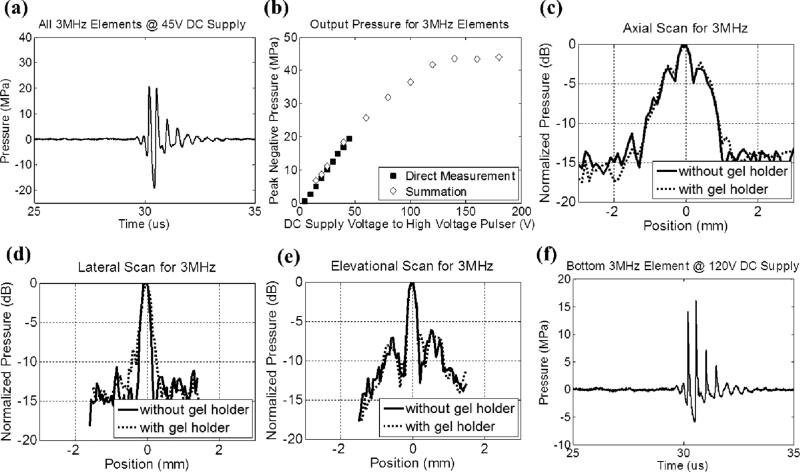
Fig. 4 shows the calibration results of the 3 MHz component (a total of 7 elements without the top element) in free-field, including a representative focal pressure waveform before inducing cavitation on the FOPH [Fig. 4(a)], total focal P– as a function of DC supply voltage to the high-voltage pulser [Fig. 4(b)], and one-dimensional (1D) beam profiles in the axial [Fig. 4(c)], lateral [Fig. 4(d)], and elevational [Fig. 4(e)] directions. Phase correction was performed to compensate for any misalignment of the 3 MHz elements. The 6 dB beam-widths (calculated based on P–) were measured to be 1.42 (axial), 0.31 (lateral) and 0.31 (elevational) mm. Fig. 4(f) shows a representative focal pressure waveform from the bottom element at the pressure level used in the 3rd experimental set that varied the relative propagation directions between 500 kHz and 3 MHz components. Note that the waveforms in Figs. 3(a) and 4(a) were not as nonlinear as the ones shown in our previous works [1, 2, 4-8], this was likely due to 1) this array transducer having a lower f-number (approximately 0.56 for 500 kHz components and 0.50 for 3MHz components), and 2) each element having an individual focusing lens such that acoustic beams from adjacent elements did not overlap significantly until they reached the common geometric focus.
Fig. 4.
Calibration results of the 3MHz component in the dual-frequency array transducer. (a) A representative free-field focal acoustic waveform measured directly with all seven 3MHz elements (without the top element) firing concurrently. (b) Peak negative pressure as a function of the DC supply voltage to the high voltage pulser. Solid squares (■) represent pressures from direct measurements with all 7 elements firing concurrently, while empty diamonds (◇) represent the estimates from the summation of the individual elements firing separately. (c) 1D beam profile (with all 7 elements firing) in the axial direction with (dotted line) and without (solid line) the gel holder. (d) 1D beam profile (with all 7 elements firing) in the lateral direction with (dotted line) and without (solid line) the gel holder. (e) 1D beam profile (with all 7 elements firing) in the elevational direction with (dotted line) and without (solid line) the gel holder. The gel holder here is a representative holder for RBC phantom experiments.(f) A representative free-field focal acoustic waveform of an individual element (the bottom element) at the pressure level used in the 3rd experimental set that investigated the effect of relative propagation direction between 500 kHz and 3 MHz pulses.
Cylindrical, custom-made, plastic gel holders (4 cm in diameter and 8 cm in height) with thin polycarbonate membranes (254 μm thick) glued on their sides, as shown in Fig. 1(b), were used to hold the RBC phantoms. Based on the calibration with a representative plastic gel holder in place, the P– values were attenuated by 8.2% (500 kHz) and 9.1% (3 MHz); however, the 1D beam profiles did not change significantly, as shown in Figs. 3 (c) – 3(e) and 4(c) – 4(e). Note that the attenuations for 500 kHz and 3 MHz did not scale with the frequency, and this was likely due to the difference in their incidental angles on the gel holder (3MHz elements had almost normal incidence while 500 kHz elements had oblique incidence). In the ex vivo porcine liver experiment, another type of cylindrical gel holder [Fig. 1(c), 3cm in diameter and 6 cm in height] with thinner polycarbonate membranes (127 μm thick) was used to hold agarose-embedded hepatic specimens. Based on the calibration with this type of gel holder in place, the P– values were attenuated by 1.0% (500 kHz) and 6.8% (3 MHz). The attenuation for 500 kHz in this type of gel holder was significantly less than the former gel holders since this type of holder had an opening at the bottom, which was in the propagation paths of some 500 kHz elements.
The applied pressure levels used in the experiments are listed in Table I and II. The applied P– was corrected by the attenuation contributed by the plastic gel holder using the hydrophone measurement discussed above. Additionally, the applied P– was further corrected for the attenuation contributed by agarose hydrogel and porcine hepatic specimen, using reported values [10, 21, 23] and assuming linear propagation.
TABLE I.
PEAK NEGATIVE PRESSURES AND TIME DELAYS FOR CAPTURING BUBBLE CLOUD IMAGES USED IN RBC PHANTOM EXPERIMENTS
| Experimental Set | Case | 500 kHZ |
3MHz |
Time Delay For Capturing Bubble Cloud Images (μs) | ||||
|---|---|---|---|---|---|---|---|---|
| Focal P– in Free-Field (MPa)* | Focal P– with Attenuation Correction (MPa) | Proportion (%) | Focal P– in Free-Field (MPa)* | Focal P– with Attenuation Correction (MPa) | Proportion (%) | |||
| 1 | every case | 11.7 | 10.6 | 38 | 20.3 | 17.1 | 62 | 9 |
| 2 | 1 | 0.0 | 0.0 | 0 | 33.0 | 27.8 | 100 | 5 |
| 2 | 11.0 | 9.9 | 35 | 21.7 | 18.2 | 65 | 8 | |
| 3 | 15.8 | 14.3 | 51 | 16.1 | 13.6 | 49 | 9 | |
| 4 | 20.8 | 18.9 | 68 | 10.8 | 9.1 | 32 | 13 | |
| 5 | 29.4 | 26.6 | 100 | 0.0 | 0.0 | 0 | 17 | |
| 3 | every case | 22.3 | 20.2 | 80 | 6.0 | 5.1 | 20 | 15 |
The P– values in Experimental Set 1, 2 (Case 2-4), and 3 were linearly interpolated using the directly measured P– values for various driving voltages. The P– values of Case 1 and 5 in Experimental Set 2 were linearly interpolated using the linearly summed P– values for various driving voltages.
TABLE II.
PEAK NEGATIVE PRESSURES USED IN EX VIVO PORCINE LIVER EXPERIMENTS
| Case | 500 kHZ |
3MHz |
||||
|---|---|---|---|---|---|---|
| Focal P– in Free-Field (MPa)* | Focal P– with Attenuation Correction (MPa) | Proportion (%) | Focal P– in Free-Field (MPa)* | Focal P– with Attenuation Correction (MPa) | Proportion (%) | |
| 1 | 17.6 | 17.0 | 53 | 19.5 | 15.3 | 47 |
| 2 | 25.5 | 24.5 | 72 | 12.4 | 10.7 | 28 |
| 3 | 32.0 | 30.8 | 100 | 0.0 | 0.0 | 0 |
The P– values in Case 1 (both frequencies) and 2 (only 3MHz component) were linearly interpolated using the directly measured P– values for various driving voltages. The P– values in Case 2 (only 500 kHz component) and 3 (only 500 kHz component) were linearly interpolated using the linearly summed P– values for various driving voltages.
C. Experiments in RBC Phantoms and Lesion Analysis
Three different experimental sets were performed in RBC phantoms to investigate lesion production using dual-beam histotripsy. The applied P– values are listed in Table I. Each intended treatment region was exposed with 100 pulses at a PRF of 1 Hz, and a single-focal-point exposure was performed.
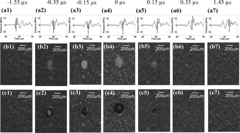
The arrival times of the 500 kHz and 3 MHz pulses were varied from no overlap to maximal P– overlap at the focus of the array transducer. More specifically, the time delay for 3 MHz relative to 500 kHz varied from –1.55 to 1.45 μs, where 0 μs is defined as the time point when the two pulses had maximal overlap in P–, and a negative time delay indicates the P– of the 3 MHz pulse arriving earlier than the P– of the 500 kHz pulse and vice versa. The applied pressures were chosen such that each individual frequency component did not reach the intrinsic threshold; rather, it could be exceeded only by the combination of the two.
The relative amplitudes of the 500 kHz and 3 MHz pulses were varied to study the smallest reproducible lesions for each combination. The arrival times of the 500 kHz and 3 MHz in this experimental set were chosen to be the time delay when the two produced the maximal P– values of the composite waveforms.
The propagation direction of the 3 MHz relative to the 500 kHz was varied from co-propagation, orthogonal-propagation, to counter-propagation to investigate effects in lesion production. In this experimental set, all 500 kHz elements were firing together with one selected 3 MHz element to implement different propagation directions. The bottom 3MHz element was chosen for the co-propagation case, one selected 3 MHz element within the 3rd ring of the array transducer was chosen for the orthogonal-propagation (85 degrees), and the 3 MHz element attached to top frame was chosen for the counter-propagation case. The arrival times of the 500 kHz and 3 MHz in this experimental set were chosen to be the time delay when the two had maximal P– overlap.
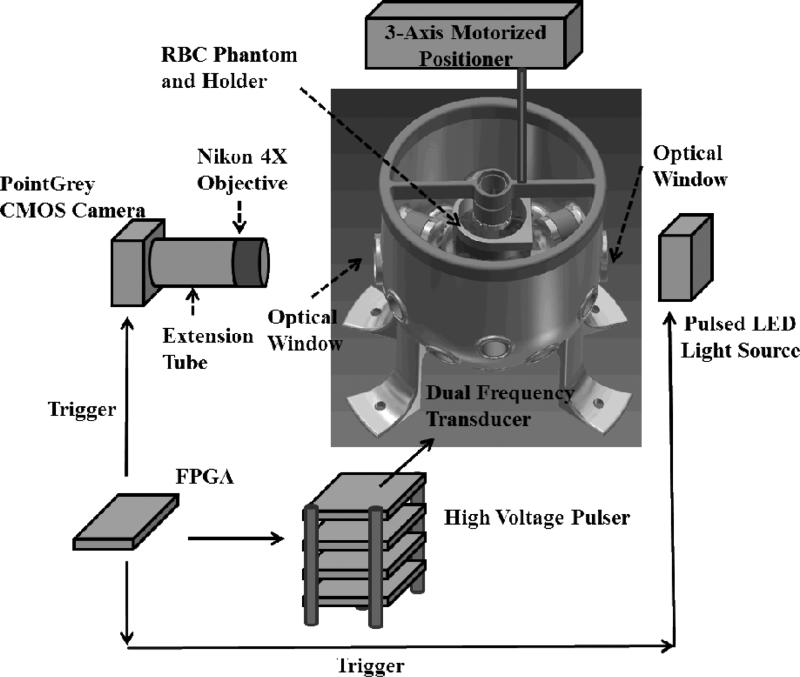
The experimental setup for the treatment in RBC Phantoms is illustrated in Fig. 5. For the visualization of the cavitational bubble clouds and their resulting damages in RBC phantoms, a digital, 1.3-megapixel, CMOS, mono-color camera (PN: FL3-U3-13Y3M-C, Flea® 3, PointGrey, Richmond, BC, Canada) was positioned perpendicularly to the dual-frequency array transducer facing one of its optical windows. A Nikon 4X objective was attached to the camera with extension tubes to magnify the image plane, giving the captured images a resolution of approximately 3.5 μm per pixel. A pulsed white-light LED was placed on the other diametrically-opposed optical window of the dual-frequency array transducer, which provided back-lit illumination. This arrangement allowed for the visualization of the axial-lateral plane of the dual-frequency array transducer. The camera and the LED light source received trigger signals from the FPGA board, which maintained the synchronization of image capturing and the delivery of histotripsy pulses. For every delivered histotripsy pulse, two images were acquired, one (bubble cloud image) at the time when the maximal spatial extent of the bubble cloud was observed (see Table I for exact timing), and the other (lesion image) at 500 ms after the arrival of the pulse, where only histotripsy-induced damage in the RBC phantom was observed. The exposure time was 2 μs for every captured image. The RBC phantoms were mounted on a 3-axis motorized positioner (Griffin Motion, Holly Springs, NC, USA) and submerged in the dual-frequency array transducer with an orientation for the visualization of axial-lateral-plane lesions.
Fig. 5.
An illustration of the overall experimental setup in RBC phantom experiments. An RBC phantom in a gel holder is mounted on a 3-axis motorized positioner and submerged in the dual-frequency array transducer with degassed water. A custom high-voltage pulser was used to drive the dual-frequency array transducer. A CMOS camera (PointGrey) is positioned next to one of the optical windows for image capturing along with a Nikon 4X objective and extension tubes for image magnification. A pulsed LED light source is positioned next to the other diametrically opposed optical window for back-lit illumination. An FPGA development board maintains the transducer firing, image capturing, and LED lighting in synchronization.
These optical images were then post-processed with MATLAB (R2011a, MathWorks, Natick, MA, USA) using a method similar to those described in previous papers [11, 21, 24]. The lesion images were converted to binary images using the threshold calculated based on the mean intensity of the lesion. In order to exclude noise in the camera sensor and pre-existing isolated small white regions due to RBC layers being not 100% uniform, lesions smaller than 237 pixels (corresponding to regions less than 30 μm in radius) were excluded from the damage zone. By counting the number of pixels identified as damage zone and converting it to actual size with the help of a pre-captured scale image, the area, length, and width of the lesion were determined. During this analysis, the lesion was divided into two groups: 1) “main lesion,” the center portion of the lesion which was induced by consistent bubble cloud presence, and 2) “peripheral damage,” the damage zone outside of main lesion which was induced by incidental bubble presence. The bubble cloud images were quantified in a similar way, except the thresholds for binary image conversion were calculated based on the mean intensity of the bubble cloud. For experimental set 1, where the arrival times for 500 kHz and 3 MHz pulses were varied, a cavitation probability was further calculated based on the number of pulses with bubble cloud presence within the total delivered 100 pulses. The cavitation probabilities for bubble clouds generated in the main lesion and incidental bubbles generated in peripheral region were quantified separately.
D. Linear Transient Simulation with Fast Object-Oriented C++ Ultrasound Simulator (FOCUS) and Lesion Size Estimation
A linear transient simulation was performed using an ultrasound simulation tool, Fast Object-Oriented C++ Ultrasound Simulator (FOCUS, Version 437 for MATLAB 2010a and Windows 64-bit operating system, developed by Dr. Robert J. McGough et al from Michigan State University, MI, USA [25-27]). FOCUS is a cross-platform (for Windows, Linux, and MacOS) “free-ware” and it is written in object-oriented C++ with MATLAB user interface. In the simulation, “spherical shells” with a diameter of 20 mm and a focal length of 40 mm were selected to represent the elements within the dual-frequency array transducer. In order to resemble the actual acoustic waveform better, the excitation pulse was chosen to be two-cycle, “Hann-weighted tone-burst” pulse with the desired frequency, amplitude, and time delay. The elements were arranged in three-dimensional (3D) space according to the design of the transducer, and 3D pressure field calculation was performed for selected two-dimensional (2D) axial-lateral planes. The function “fnm_tsd” (called “transient_pressure” in the newer version) was used to calculate the transient pressure field using fast near-field methods and time-space decomposition. The sampling frequencies in time and space domain were chosen to be 40 MHz (4 × 10⁷ samples / second) and 5 × 10⁴ samples / meter.
For experimental set #2, where the relative amplitude proportion between the 500 kHz and 3 MHz pulses was varied, lesion size estimation was performed. 2D pressure fields in the axial-lateral plane were simulated using FOCUS and extrapolated to the applied pressure level. A pressure threshold was obtained using the same method described in [11], and then applied to the extrapolated 2D pressure field to estimate lesion sizes.
E. Experiments in Ex Vivo Porcine Hepatic Specimens and Histological Evaluation
Agarose-embedded porcine hepatic specimens were mounted on the Griffin 3-axis motorized positioner, and ultrasound B-mode imaging, instead of high speed photography, was used to monitor the histotripsy treatment. The ultrasound B-mode imaging was performed using a commercial ATL HDI 5000 ultrasound scanner (Advanced Technology Laboratories, Inc., Bothell, WA, USA) with ATL L12-5 linear probe. Each intended treatment region was exposed with 500 pulses at a PRF of 1 Hz, and a single-focal-point exposure was performed. Various pressure combinations, listed in Table II, were applied to various regions of the specimens. In order to better identify smaller lesions after treatment, two large lesions (5 mm in separation) using only the 500 kHz component were generated on the surface of the specimens, along with two large lesions, also using only the 500 kHz component, generated 3 mm right beneath the two surface lesions. These four lesions were used as landmarks, and a small lesion was then generated in between these two large lesions and 3 mm beneath the surface of the tissue specimen.
The lesions were evaluated with both ultrasound B-mode imaging and histological sections after treatment. A high-frequency ultrasound probe, RMV 707B (15 – 45 MHz, VisualSonics, Toronto, ON, Canada), along with a high-frequency ultrasound scanner, Vevo 770 (VisualSonics), was used to image the lesions after treatment. The axial and lateral dimensions of the lesions were then measured based on the hypoechoic regions that appeared in the recorded B-mode images. For histological evaluation, the treated porcine specimens were fixed with 10% phosphate buffered formalin (Fisher Scientific, Fair Lawn, NJ, USA) and sectioned into approximate 3-mm-thick slices along the axial-lateral planes of the lesions using a regular kitchen knife and surgical scalpels. These slices were then further processed into 4-μm-thick histological sections with 100 μm sectioning step size using a microtome and stained with hematoxylin and eosin (H&E). Visual inspection using bright field microscopy was performed to identify the section with maximal spatial extent of the damage among all sections for each sample. The maximal extents of the lesions in the lateral and axial directions were quantified based on the bright field microscopic images with the help of a pre-calibrated scale.
III. RESULTS
A. Experiments in RBC Phantoms
1) Varying Time Delays between 500 kHz and 3 MHz Pulses
A total of 13 time delays were investigated, including –1.55, –0.65, –0.35, –0.25, –0.15, –0.05, 0.00, 0.05, 0.15, 0.25, 0.35, 0.65, 1.45 μs. The sample size for each case was nine, leading to a total of 117 lesions generated in RBC phantoms. Figs. 6 and 7 summarize the result for this experimental set.
Fig. 6.
Results for the experimental set that varied the time delay between the pump (500 kHz) and probe (3 MHz) pulses. The labels on the very top indicate the time delay for each column. 0 μs is defined as the time delay that resulted in maximal P– overlap, and negative time delays are defined as the cases when the probe arrives earlier than the pump, and vice versa. Figures in the top row (a1 - a7) represent the pressure waveforms in free-field for each corresponding time delay. Due to limitation in hydrophone calibration, these waveforms were measured by the FOPH at a lower pressure level(~ ½ of the pressure used in the RBC experiments). Figures in middle row (b1 - b7) show representative lesion images in RBC phantoms after 100 histotripsy pulses for each corresponding time delay. Figures in bottom row (c1- c7) show representative bubble cloud images in RBC phantoms. All the bubble cloud and lesion images were taken in the axial-lateral plane of the transducer and the histotripsy pulses propagated from bottom to the top.
Fig. 7.
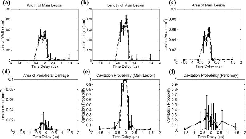
Quantitative results for the experimental set that varied the time delay between pump (500 kHz) and probe (3 MHz). The results in the focus (main lesion) and periphery (peripheral damage) were quantified separately. The vertical bars in all the figures represent +/– one standard deviation, and the sample size for each case is nine (N=9). (a) Width (lesion size in the lateral direction) of the main lesion, (b) length (lesion size in the axial direction) of the main lesion, (c) area of the main lesion, (d) area of the peripheral damage, (e) cavitation probability in the main lesion, and (f) cavitation probability in the periphery as a function of the time delay. The cavitation probability is calculated by counting the number of pulses that have initiated bubble clouds (quantified based on optical imaging) and dividing this number by 100, which is the number of total delivered histotripsy pulses.
Fig. 6 shows directly measured acoustic waveforms (at a pressure level [combined P– = ~14 MPa] lower than that used in the RBC experiments) and representative lesion and bubble cloud images for various time delays. In order to increase readability, only 7 time delays (every other case) are shown. As can be seen from the figure, cavitational bubbles and lesions only occurred when the negative pressure peaks of the 500 kHz and 3 MHz pulses overlapped and added constructively. Neither lesions nor cavitational bubbles occurred where the negative pressure peaks of the 500 kHz and 3 MHz pulses did not overlap.
Fig. 7 shows the quantitative result after lesion analysis, including width [Fig. 7(a)], length [Fig. 7(b)], and area [Fig. 7(c)] of the main lesion, area of the peripheral damage [Fig. 7(d)], and cavitation probabilities in main lesion [Fig. 7(e)] and periphery [Fig. 7(f)]. As can be seen, the width, length, area, and cavitation probability of the main lesion reached their maxima at 0 μs time delay, i.e., 500 kHz and 3 MHz pulses had maximal P– overlap. No significant changes were observed when the time delay changed to –0.05 or 0.05 μs. When the time delay changed to even more negative or positive, the lesion size and cavitation probability in the main lesion decreased due to a reduction of combined P–. When the time delay was earlier than –0.50 μs or later than 0.20 μs, the cavitation probability in the main lesion decreased to less than 10%, and almost no lesions were observed. The lesion area and cavitation probability for the periphery showed a similar trend. Although their maxima both appeared at –0.25 μs time delay, they did not differ significantly from those at 0 μs.
2) Varying Relative Amplitudes between 500 kHz and 3 MHz Pulses
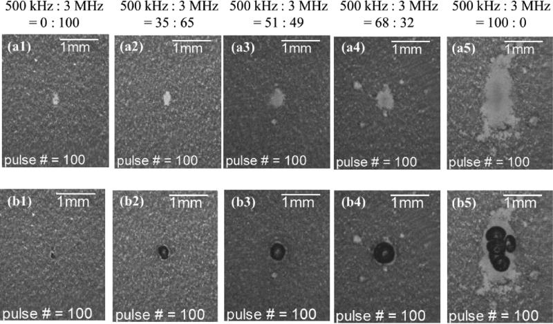
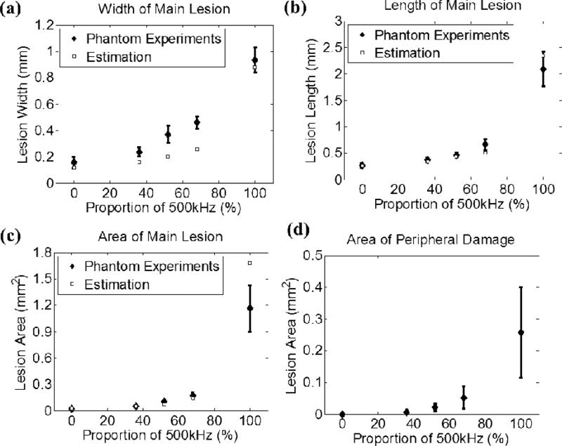
A total of 5 different combinations, as listed in Table I, were investigated, and each case had a sample size of six. Fig. 8 shows representative lesion and bubble cloud images for each case. Fig. 9 summarizes the quantitative results for the width [Fig. 9(a)], length [Fig. 9(b)] and area [Fig. 9(c)] of the main lesion and the area of the peripheral damage [Fig. 9(d)]. As can be seen, the sizes of the lesions and bubble clouds increased as the relative proportion of the 500 kHz pulse amplitude increased. Size estimations for main lesions using FOCUS simulation tool are also plotted in Figs. 9(a) – 9(c), and the estimations have a general agreement with phantom experiment results.
Fig. 8.
Results for the experimental set that varied the relative amplitude between the probe (3 MHz) and pump (500 kHz) pulses. The labels on the very top indicate the corresponding relative amplitude between the pump and probe pulses for each column. Figures in the first row (a1 - a5) show representative lesion images after 100 delivered histotripsy pulses in RBC phantoms. Figures in the second row (b1 - b5) show representative bubble cloud images in RBC phantoms. All the bubble cloud and lesion images were taken in the axial-lateral plane of the transducer and the histotripsy pulses propagated from bottom to the top.
Fig. 9.
Quantitative results, along with estimations using FOCUS simulation, for the experimental set that varied the relative amplitude between the probe (3 MHz) and pump (500 kHz) pulses. The vertical bars in all the figures represent +/– one standard deviation, and the sample size for each case is six (N=6). (a) Width (lesion size in the lateral direction) of the main lesion, (b) length (lesion size in the axial direction) of the main lesion, (c) area of the main lesion, and (d) area of the peripheral damage as a function of the amplitude proportion of the applied 500 kHz pulse.
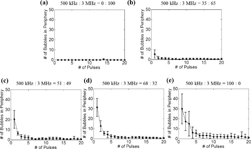
Fig. 10 shows the number of incidental bubbles generated at the periphery, which are responsible for peripheral damage, as a function of the number of applied histotripsy pulses. As can be seen, the number of these bubbles started from its maximal value and rapidly decreased to almost no bubble presence after the 10th pulse. Additionally, when the 500 kHz pulse amplitude fraction was higher, the number of incidental bubbles at the periphery increased and these bubbles disappeared more slowly.
Fig. 10.
Number of incidental bubbles generated in the periphery of the focus during the experimental set that varied the relative amplitude between the probe (3 MHz) and pump (500 kHz) pulses. Results after 20 pulses are not plotted since they are similar as the result of the 20th pulse. The vertical bars in all the figures represent +/– one standard deviation, and the sample size for each case is six (N=6).
3) Varying Propagation Direction of the 3 MHz Pulse Relative to the 500 kHz Pulse
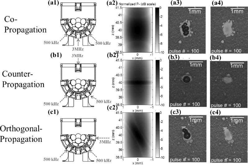
The propagation direction was varied from co-propagation, then counter-propagation, and to orthogonal-propagation, and each had a sample size of eight. Fig. 11 shows the corresponding transducer firing arrangements [Figs. 11(a1), 11(b1), and 11 (c1)], 2D pressure fields using FOCUS simulations [Figs. 11(a2), 11(b2), and 11 (c2)], bubble cloud images [Figs. 11(a3), 11(b3), and 11 (c3)], and lesion images [Figs. 11(a4), 11(b4), and 11 (c4)] for different propagation directions. As can be seen, the lesion length in the axial direction for the counter-propagation case was significantly smaller than that for co-propagation case. Also, the lesion shape seemed tilted in the orthogonal-propagation case in comparison to that in the co-propagation case. These results correspond well to the simulated 2D pressure (P–) fields.
Fig. 11.
Results for the experimental set that varied the propagation direction of the probe (3 MHz) pulse relative to the pump (500 kHz) pulse. The labels on the very left indicate the corresponding propagation direction for each row. Figures in the first column (a1, b1, and c1) illustrate the corresponding transducer firing arrangements. Figures in the second column (a2, b2, and c2) show 2D pressure fields (normalized P– in dB scale) using linear transient simulation with FOCUS. Figures in the third column (a3, b3, and c3) show representative bubble cloud images in RBC phantoms. Figures in the fourth column (a4, b4, and c4) show representative lesion images after 100 delivered histotripsy pulses in RBC phantoms.All the bubble cloud and lesion images were taken in the axial-lateral plane of the transducer and the 500 kHz pulses propagated from bottom to the top.
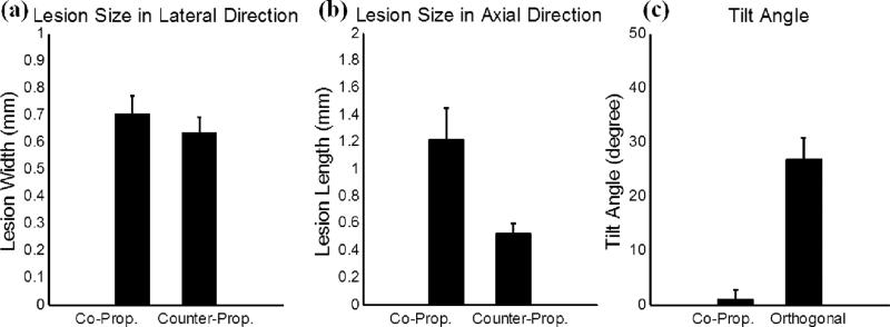
The quantitative analysis of these lesions is summarized in Fig. 12. The lesion size in the axial direction changed significantly from 1.21 mm for the co-propagation case to 0.52 mm for the counter-propagation case, while the lesion size in the lateral direction remained in similar level (0.70 mm for the co-propagation case and 0.63 mm for the counter-propagation case). The tilt angle changed from 1.0 degree for the co-propagation case to 26.8 degrees for the orthogonal-propagation case. This tilt angle was quantified by manually selecting the top and bottom points of the lesion, forming a central axis of the lesion, and then calculating the angle between this central axis and the axial propagation direction of the 500 kHz pulse component.
Fig. 12.
Quantitative results for the experimental set that varied the propagation direction of the probe (3 MHz) pulse relative to the pump (500 kHz) pulse. The vertical bars in all the figures represent + one standard deviation, and the sample size for each case is eight (N=8). (a) A comparison between copropagation and counter-propagation for the width (lesion size in the lateral direction) of the main lesion. (b) A comparison between co-propagation and counter-propagation for the length (lesion size in the axial direction) of the main lesion. (c) A comparison between co-propagation and orthogonal propagation for the tilt angle of the main lesion.
B. Experiments in Ex Vivo Porcine Hepatic Specimens
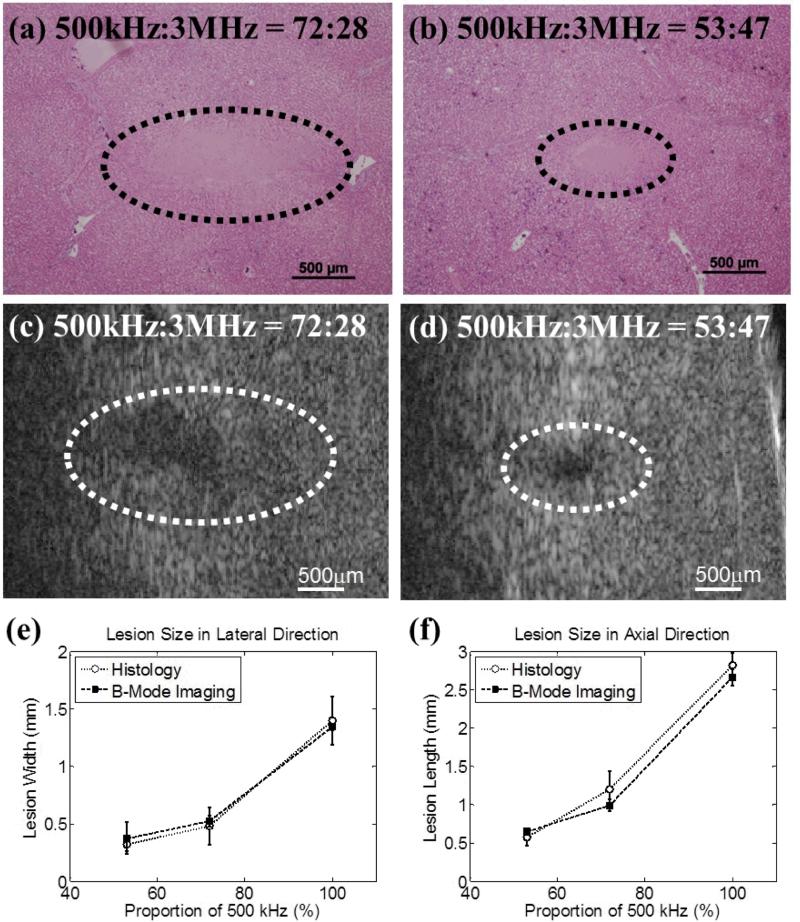
A total of 3 different pressure combinations, as listed in Table II, were used to generate lesions in ex vivo porcine hepatic specimens, and each case had a sample size of two (N = 2). The representative histological sections are displayed in Figs. 13(a) and 13(b). The intended treatment regions had lost their normal architecture and contained only acellular granular debris, and a larger spatial extent of the lesion occurred when a higher proportion of the 500 kHz pulse was applied. Figs. 13(c) and 13(d) show representative B-mode images of the hepatic specimens after the application of 500 histotripsy pulses. Note that the B-mode ultrasound images were rotated 90 degrees from their original orientations in order to match the orientations of the histological sections. Hypoechoic regions occurred on B-mode images after histotripsy treatment, and these regions were larger when a higher proportion of 500 kHz pulse was applied. The histological sections and B-mode images for the case with 100% proportion of 500 kHz pulse are not displayed in Fig. 13 since this paper focuses on using both pump (500 kHz) and probe (3MHz) pulses. The quantified lesion sizes in the lateral and axial directions are shown in Figs. 13(e) and 13(f), respectively. As can be seen, the quantified lesion sizes increased as the proportion of the 500 kHz pulse increased and the results quantified from histological sections and B-mode images were close to each other.
Fig. 13.
The results for excised porcine hepatic tissue treatment. The representative histological section and B-mode image for 500 kHz : 3 MHz = 72:28 are shown in (a) and (c), respectively. The representative histological section and B-mode image for 500 kHz : 3 MHz = 53:47 are shown in (b) and (d), respectively. Histological sections and B-mode ultrasound images were both taken in the axial-lateral plane of the transducer and histotripsy pulses propagated from right to the left. The B-mode ultrasound images were rotated 90 degrees from their original orientations in order to match the displayed orientations of the histological sections. The quantified lesion sizes in the lateral and axial directions are shown in (e) and (f), respectively. Empty circles together with dotted lines (...○...) indicate results quantified from histological sections, while solid squares together with dashed lines (---■---) indicate results quantified from B-mode images. The vertical bars in these two figures represent +/– one standard deviation, and the sample size for each case is two (N = 2).
IV. Discussion
In this paper, precise lesions were generated by “dual-beam histotripsy” pulses using the intrinsic threshold mechanism in both RBC phantoms and ex vivo porcine specimens. The dual-beam histotripsy pulse is comprised of a low-frequency pump pulse and a high-frequency probe pulse wherein a proper time delay between the two is chosen to allow their P– values to add constructively at the focus so as to exceed the intrinsic cavitation threshold. As can be seen in Figs. 6 and 7, when the pump and probe pulses had maximal P– overlap (i.e. 0 μs time delay), consistent bubble clouds were generated with a cavitation probability of 100% and the size of the main lesion reached its maximum. No significant changes in the cavitation probability and lesion size were observed when the probe pulse (3 MHz) arrived 0.05 μs earlier or later than the pump pulse (500 kHz). When the time delay between the negative pressure peaks of the pump and probe pulses increased to 0.15 μs or more, the diminution of the combined P– led to decreases in the cavitation probability and lesion size (with higher variability), and both the cavitation probability and lesion size approached 0 when the negative phases of the pump and probe pulses did not have any overlap. Furthermore, these decreases were not symmetric around 0 μs time delay, which was likely due to the negative pressure phase for the 500 kHz pulse (in time domain) not being symmetric, as can be seen in Fig. 3(a). This asymmetry in the 500 kHz waveform was probably not a result of nonlinear propagation since it also occurred at really low applied pressure level. Misalignment of individual elements was probably not the cause since phase corrections in free field for individual elements were performed during the calibration process for the phantom and tissue experiments. Imperfection in the stacking process during element assembly is a potential explanation since it only occurred in the epoxy-stacked 500 kHz elements.
Additionally, the size of the smallest reproducible lesions decreased when a higher proportion of the probe pulse (3 MHz) was applied, as indicated in Figs. 8 and 9. With only 32% of the probe pulse, the lesion size decreased significantly from where pulses with 100% 500 kHz were applied. The lesion width decreased from 0.93 to 0.46 mm, the lesion length decreased from 2.09 to 0.66 mm, and the lesion area decreased from 1.16 to 0.17 mm2. This demonstrates that, with the addition of a minor portion of the probe pulse, significantly smaller lesions can be achieved, in comparison to 100% pump pulse. This has a general agreement with a linear simulation using FOCUS as seen in Fig. 9.
Moreover, the size and shape of the produced lesions can be further manipulated using various propagation directions between pump and probe pulses. (1) The axial dimension of the lesion can be further reduced when a probe pulse counter-propagates with a pump pulse, as shown in Figs. 11 and 12. This “foreshortening” of the lesion results from the very short interaction time window when two short acoustic pulses (only one large negative pressure phase in the 2-cycle pulses) counter-propagate with each other (note that CW waves would not produce the same effect). (2) When a probe pulse orthogonally-propagates with a pump pulse, the lesion can be “tilted” from the propagation axis of the pump pulse. As shown in Figs 11 (c1) – 11 (c4), when the pump pulse propagates from the bottom to the top and the probe pulse propagates from the right to the left, they firstly interact in the lower right corner of the focus. As they propagate through the focus, the two pulses produce a supra-threshold region moving from the lower right to the upper left, making the lesion appear tilted from the propagation axis of the pump pulse. Though using propagation directions other than co-propagation might not work in many applications due to the lack of accessible acoustic windows, it might still be applicable in some situations. For example, a transrectal probe pulse counter-propagating with transabdominal pump pulse could be used in prostatic tissue ablation. Counter- or orthogonal-propagation of catheter-based probe pulses with transcostal/transabdominal pump pulses might also have potential in cardiac or hepatic tissue treatment allowing pulses from small-aperture high-frequency transducers to reach threshold levels not possible when used alone.
Peripheral damage induced by the incidental bubbles generated at the periphery of the focus was observed in both single-frequency histotripsy and dual-beam histotripsy (pump + probe). These incidental bubbles almost disappeared by the time the 20th pulse was applied. A higher proportion of the pump pulse led to a larger area of peripheral damage, a larger number of incidental bubbles, and a slower rate in the decrease of the number of incidental bubbles. These incidental bubbles were likely seeded from the pre-existing dissolved sub-micron gas bubbles (samples could not be 100% degassed) or weak pockets. The application of histotripsy pulses firstly excited these weak nuclei at the periphery (where P– was below the intrinsic threshold) and then subsequently destabilized them, causing the incidental bubbles to disappear quickly. After that, the bubble clouds were preferentially generated at the location where the main lesion was forming. This “self-quenching” phenomenon limits the damage in the periphery, containing the lesion primarily to the volume where P– exceeds the intrinsic threshold.
Thus, “dual-beam histotripsy” can be quite beneficial in situations where precise treatment is required through a highly aberrative and attenuative medium. In the situation covered in this paper, the pump pulse is highly focused and can only cover a small region (–6dB beamwidths: 4.9 × 1.7 × 1.8 mm) or “target” for the probe pulse. In practice, it would be more ideal if the pump pulse could cover a larger ROI and the P– level could be raised uniformly across the volume. Therefore, we plan to investigate a lower-frequency pump with higher f-number (less focused) in the future. We also plan to study the feasibility of using commercial imaging transducers for probe pulse generation. This could provide not only the steering capability for the probe pulse during treatment, but also the image guidance and feedback if it is used in conjunction with an imaging system. An imaging probe dual-beam histotripsy system could use available small windows, e.g., the transcostal region between ribs, to generate precise high frequency steerable pulses “enabled” by a much larger low-frequency pump transducer (e.g. , covering much of the rib cage). The use of a high frequency imaging transducer to generate precise lesions has many other interesting applications.
V. Conclusion
In this study, the capability of “dual-beam histotripsy” pulses for precise lesion formation is demonstrated both in RBC phantoms and ex vivo porcine tissues. Dual-beam histotripsy is accomplished by the application of a low-frequency pump pulse that enables a high-frequency probe pulse to exceed the intrinsic cavitation threshold. With an adjustment in arrival times that allows constructive P– addition at the focus, sub-intrinsic-threshold pump and probe pulses can induce dense bubble cloud generation when P– summation exceeds the intrinsic cavitation threshold. The size of the smallest reproducible lesions decreases when the proportion of the probe pulse increases. Counter-propagation of the pump and probe pulse could foreshorten the lesion size in the axial direction. Dual-beam histotripsy can be useful in clinical applications where precise tissue ablation is required with a longer propagation depth or through a highly attenuative or aberrative medium, such as transcranial therapy. With small low-attenuation “windows,” even imaging transducers providing the probe pulses could generate histotripsy lesions.
Supplementary Material
Acknowledgement
The authors thank Dr. Robert J. McGough for the discussion and help in linear transient simulation using FOCUS and Dr. Cheri X. Deng for letting us use her VisualSonics Vevo770 system. This work is supported by the National Institute of Health (grants R01 CA134579, R01 EB008998, and R01 DK091267), the Hartwell Foundation, and a Research Scholar Grant from the American Cancer Society (RSG-13-101-01-CCE). Drs. Timothy L. Hall, Zhen Xu, and Charles A. Cain have financial interest and/or other relationship with HistoSonics.
REFERENCES
- 1.Xu Z, Ludomirsky A, Eun LY, Hall TL, Tran BC, Fowlkes JB, Cain CA. Controlled ultrasound tissue erosion. IEEE Trans Ultrason Ferroelectr Freq Control. 2004 Jun;51:726–36. doi: 10.1109/tuffc.2004.1308731. [DOI] [PMC free article] [PubMed] [Google Scholar]
- 2.Xu Z, Owens G, Gordon D, Cain C, Ludomirsky A. Noninvasive creation of an atrial septal defect by histotripsy in a canine model. Circulation. 2010 Feb 16;121:742–9. doi: 10.1161/CIRCULATIONAHA.109.889071. [DOI] [PMC free article] [PubMed] [Google Scholar]
- 3.Owens GE, Miller RM, Ensing G, Ives K, Gordon D, Ludomirsky A, Xu Z. Therapeutic ultrasound to noninvasively create intracardiac communications in an intact animal model. Catheterization and Cardiovascular Interventions. 2011;77:580–588. doi: 10.1002/ccd.22787. [DOI] [PMC free article] [PubMed] [Google Scholar]
- 4.Parsons JE, Cain CA, Abrams GD, Fowlkes JB. Pulsed cavitational ultrasound therapy for controlled tissue homogenization. Ultrasound Med Biol. 2006 Jan;32:115–29. doi: 10.1016/j.ultrasmedbio.2005.09.005. [DOI] [PubMed] [Google Scholar]
- 5.Roberts WW. Focused ultrasound ablation of renal and prostate cancer: current technology and future directions. Urol Oncol. 2005 Sep-Oct;23:367–71. doi: 10.1016/j.urolonc.2005.05.022. [DOI] [PubMed] [Google Scholar]
- 6.Lake AM, Hall TL, Kieran K, Fowlkes JB, Cain CA, Roberts WW. Histotripsy: Minimally Invasive Technology for Prostatic Tissue Ablation in an In Vivo Canine Model. Urology. 2008;72:682–686. doi: 10.1016/j.urology.2008.01.037. [DOI] [PMC free article] [PubMed] [Google Scholar]
- 7.Duryea AP, Hall TL, Maxwell AD, Xu Z, Cain CA, Roberts WW. Histotripsy erosion of model urinary calculi. J Endourol. 2011 Feb;25:341–4. doi: 10.1089/end.2010.0407. [DOI] [PMC free article] [PubMed] [Google Scholar]
- 8.Duryea AP, Maxwell AD, Roberts WW, Xu Z, Hall TL, Cain CA. In vitro comminution of model renal calculi using histotripsy. IEEE Trans Ultrason Ferroelectr Freq Control. 2011 May;58:971–80. doi: 10.1109/TUFFC.2011.1898. [DOI] [PMC free article] [PubMed] [Google Scholar]
- 9.Maxwell AD, Wang TY, Cain CA, Fowlkes JB, Sapozhnikov OA, Bailey MR, Xu Z. Cavitation clouds created by shock scattering from bubbles during histotripsy. J Acoust Soc Am. 2011 Oct;130:1888–98. doi: 10.1121/1.3625239. [DOI] [PMC free article] [PubMed] [Google Scholar]
- 10.Maxwell AD, Cain CA, Hall TL, Fowlkes JB, Xu Z. Probability of Cavitation for Single Ultrasound Pulses Applied to Tissues and Tissue-Mimicking Materials. Ultrasound Med Biol. 2013;39:449–465. doi: 10.1016/j.ultrasmedbio.2012.09.004. [DOI] [PMC free article] [PubMed] [Google Scholar]
- 11.Lin K-W, Kim Y, Maxwell AD, Wang T-Y, Hall TL, Xu Z, Fowlkes JB, Cain CA. Histotripsy beyond the Intrinsic Cavitation Threshold using Very Short Ultrasound Pulses: Microtripsy. IEEE Trans Ultrason Ferroelectr Freq Control. 2013 doi: 10.1109/TUFFC.2014.6722611. (In Press), accepted September. [DOI] [PMC free article] [PubMed] [Google Scholar]
- 12.Umemura S.-i., Kawabata K.-i., Sasaki K. In vitro and in vivo enhancement of sonodynamically active cavitation by second-harmonic superimposition. J Acoust Soc Am. 1997;101:569–577. doi: 10.1121/1.418120. [DOI] [PubMed] [Google Scholar]
- 13.Yoshizawa S, Yasuda J, Umemura S.-i. High-speed observation of bubble cloud generation near a rigid wall by second-harmonic superimposed ultrasound. J Acoust Soc Am. 2013;134:1515–1520. doi: 10.1121/1.4812870. [DOI] [PubMed] [Google Scholar]
- 14.Chapelon JY, Dupenloup F, Cohen H, Lenz P. Reduction of cavitation using pseudorandom signals [therapeutic US] Ultrasonics, Ferroelectrics and Frequency Control, IEEE Transactions on. 1996;43:623–625. [Google Scholar]
- 15.Sokka SD, Gauthier TP, Hynynen K. Theoretical and experimental validation of a dual-frequency excitation method for spatial control of cavitation. Physics in Medicine and Biology. 2005;50:2167–2197. doi: 10.1088/0031-9155/50/9/017. [DOI] [PubMed] [Google Scholar]
- 16.Matsumoto Y, Yoshizawa S, Ikeda T. Dynamics of bubble cloud in focused ultrasound. Proc. 2nd ISTU, Seattle, USA. 2002:290–299. [Google Scholar]
- 17.Ikeda T, Tosaki M, Matsumoto Y, Ohta N, Kitamura T. Renal stone comminution utilizing cloud cavitation erosion. Proc. 3rd ISTU, Lyon, France. 2003:49–55. [Google Scholar]
- 18.Ikeda T, Yoshizawa S, Tosaki M, Allen JS, Takagi S, Ohta N, Kitamura T, Matsumoto Y. Cloud cavitation control for lithotripsy using high intensity focused ultrasound. Ultrasound in Medicine & Biology. 2006;32:1383–1397. doi: 10.1016/j.ultrasmedbio.2006.05.010. [DOI] [PubMed] [Google Scholar]
- 19.Liu H-L, Hsieh C-M. Single-transducer dual-frequency ultrasound generation to enhance acoustic cavitation. Ultrasonics Sonochemistry. 2009;16:431–438. doi: 10.1016/j.ultsonch.2008.08.009. [DOI] [PubMed] [Google Scholar]
- 20.Hasanzadeh H, Mokhtari-Dizaji M, Zahra Bathaie S, Hassan ZM, Nilchiani V, Goudarzi H. Enhancement and control of acoustic cavitation yield by low-level dual frequency sonication: A subharmonic analysis. Ultrasonics Sonochemistry. 2011;18:394–400. doi: 10.1016/j.ultsonch.2010.07.005. [DOI] [PubMed] [Google Scholar]
- 21.Maxwell AD, Wang T-Y, Yuan L, Duryea AP, Xu Z, Cain CA. A Tissue Phantom for Visualization and Measurement of Ultrasound-Induced Cavitation Damage. Ultrasound in Medicine & Biology. 2010;36:2132–2143. doi: 10.1016/j.ultrasmedbio.2010.08.023. [DOI] [PMC free article] [PubMed] [Google Scholar]
- 22.Parsons JE, Cain CA, Fowlkes JB. Cost-effective assembly of a basic fiber-optic hydrophone for measurement of high-amplitude therapeutic ultrasound fields. J Acoust Soc Am. 2006 Mar;119:1432–40. doi: 10.1121/1.2166708. [DOI] [PubMed] [Google Scholar]
- 23.Mast TD. Empirical relationships between acoustic parameters in human soft tissues. Acoustics Research Letters Online. 2000;1:37–42. [Google Scholar]
- 24.Wang T-Y, Xu Z, Hall TL, Fowlkes JB, Cain CA. An Efficient Treatment Strategy for Histotripsy by Removing Cavitation Memory. Ultrasound in Medicine & Biology. 2012;38:753–766. doi: 10.1016/j.ultrasmedbio.2012.01.013. [DOI] [PMC free article] [PubMed] [Google Scholar]
- 25.Chen D, McGough RJ. A 2D fast near-field method for calculating near-field pressures generated by apodized rectangular pistons. J Acoust Soc Am. 2008;124:1526–1537. doi: 10.1121/1.2950081. [DOI] [PMC free article] [PubMed] [Google Scholar]
- 26.Kelly JF, McGough RJ. Transient Fields Generated by Spherical Shells in Viscous Media. AIP Conference Proceedings. 2009;1113:210–214. [Google Scholar]
- 27.Kelly JF, McGough RJ. A time-space decomposition method for calculating the nearfield pressure generated by a pulsed circular piston. Ultrasonics, Ferroelectrics and Frequency Control, IEEE Transactions on. 2006;53:1150–1159. doi: 10.1109/tuffc.2006.1642513. [DOI] [PMC free article] [PubMed] [Google Scholar]
Associated Data
This section collects any data citations, data availability statements, or supplementary materials included in this article.


