Abstract
Purpose: Cone-beam computed tomography (CBCT) is an increasingly utilized imaging modality for the diagnosis and treatment planning of the patients with craniomaxillofacial (CMF) deformities. Accurate segmentation of CBCT image is an essential step to generate three-dimensional (3D) models for the diagnosis and treatment planning of the patients with CMF deformities. However, due to the poor image quality, including very low signal-to-noise ratio and the widespread image artifacts such as noise, beam hardening, and inhomogeneity, it is challenging to segment the CBCT images. In this paper, the authors present a new automatic segmentation method to address these problems.
Methods: To segment CBCT images, the authors propose a new method for fully automated CBCT segmentation by using patch-based sparse representation to (1) segment bony structures from the soft tissues and (2) further separate the mandible from the maxilla. Specifically, a region-specific registration strategy is first proposed to warp all the atlases to the current testing subject and then a sparse-based label propagation strategy is employed to estimate a patient-specific atlas from all aligned atlases. Finally, the patient-specific atlas is integrated into a maximum a posteriori probability-based convex segmentation framework for accurate segmentation.
Results: The proposed method has been evaluated on a dataset with 15 CBCT images. The effectiveness of the proposed region-specific registration strategy and patient-specific atlas has been validated by comparing with the traditional registration strategy and population-based atlas. The experimental results show that the proposed method achieves the best segmentation accuracy by comparison with other state-of-the-art segmentation methods.
Conclusions: The authors have proposed a new CBCT segmentation method by using patch-based sparse representation and convex optimization, which can achieve considerably accurate segmentation results in CBCT segmentation based on 15 patients.
Keywords: CBCT, atlas-based segmentation, patient-specific atlas, sparse representation, elastic net, convex optimization
INTRODUCTION
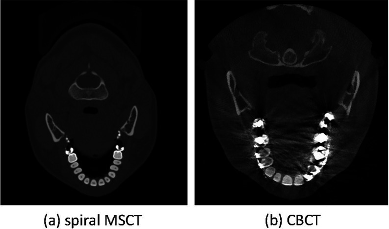
Segmentation of the cone-beam computed topographic (CBCT) image is an essential step for generating three-dimensional (3D) models in the diagnosis and treatment planning of the patients with craniomaxillofacial (CMF) deformities. It requires segmentation of bony structures from soft tissues, as well as separation of mandible from maxilla. CBCT scanners are becoming popularly used in the clinic, even in the private practice settings, due to its lower cost and lower dose compared to the conventional spiral multislice CT (MSCT) scanners.1 However, the quality of CBCT images is significantly lower than that of spiral MSCT [Fig. 1a]. Also, there are many imaging artifacts [Fig. 1b], including noise, beam hardening, inhomogeneity, and truncation, that are inherent in CBCT units due to the nature of imaging acquisition and reconstruction process.2 For example, CBCT machines for the purpose of dose reduction are often operated at milliamperes that are approximately one order of magnitude below those of medical CT machines. Thus, the signal-to-noise ratio of CBCT is much lower than that of CT. These artifacts affect image quality, and eventually the accuracy of subsequent segmentation.3, 4 Furthermore, based on the clinical requirement for correctly quantifying the deformity, CBCT scans are often acquired when the maxillary (upper) and mandibular (lower) teeth are in maximal intercuspation, i.e., the upper and lower teeth closely bite together as shown in Fig. 2. This leads to the display of both upper and lower teeth on the same cross-sectional slice as in Fig. 2c, thus making it extremely difficult to separate them in the same slice.5 To date, in order to use CBCT clinically for the diagnosis and treatment planning, the segmentation has to be done completely manually by the experienced operators.
Figure 1.
Comparison between (a) spiral MSCT and (b) CBCT images. Comparing to the MSCT, CBCT scans have severe image artifacts, including noise, beam hardening, inhomogeneity, and truncation.
Figure 2.

(a) Maximal intercuspation. (b) Zoomed view of the teeth. (c) Both upper and lower teeth are displayed on the same cross-sectional slice.
However, manual segmentation is tedious, time-consuming, and error-prone.6, 7 Although automated segmentation methods have been previously developed for CBCT segmentation, they were mainly based on simple thresholding and morphological operations,8 thus sensitive to the presence of the artifacts. Recently, statistical shape model (SSM) has been utilized for robust segmentation of the mandible.9, 10 However, these approaches are only applicable to the objects with relatively regular and simple shapes (e.g., mandible). They are not applicable to the objects with complex shapes (e.g., maxilla). On the other hand, interactive segmentation approaches5, 11 were also proposed to integrate automatic segmentation with manual guidance. For example, Le et al. proposed an interactive geometric segmentation technique to separate upper and lower teeth in CT images.5 However, these interactive methods5, 11 also have difficulty in producing plausible segmentations due to the presence of artifacts such as strong metal artifacts of dental implant.5 In Ref. 12, Duy et al. proposed a fully automatic method for tooth detection and classification in CT image data. However, they only focus on the upper teeth extraction in the CT image and their separation algorithm does not work as well on CBCT as it does on CT due to the low contrast in CBCT.13 To the best of our knowledge, our work is the first study aiming to fully automatically segment (and separate) the mandible from the maxilla on CBCT images.
Recently, there is a rapidly growing interest in using patch-based sparse representation.14, 15, 16 This approach makes an assumption that image patches can be represented by sparse linear combination of image patches in an overcomplete dictionary.17, 18, 19, 20 This strategy has been applied to a good deal of image processing problems, such as image denoising,17, 18 image in-painting,21 image recognition,19, 22 image super-resolution,20 and deformable segmentations,23 achieving promising results.
In this paper, we propose a new method for fully automated CBCT segmentation by using patch-based sparse representation to (1) segment bony structures from the soft tissues and (2) further separate the mandible from the maxilla. Specifically, we first propose a region-specific registration strategy to warp all the atlases to the current testing subject and then employ a sparse-based label propagation strategy to estimate a patient-specific atlas from all aligned atlases. Then, the estimated patient-specific atlas is integrated into a convex segmentation framework based on maximum a posteriori probability (MAP) for accurate segmentation. In this paper, the atlases consist of both spiral MSCT and CBCT images. The reasons for also using spiral MSCT images as a part of the atlases include (1) although image formation process is different between spiral CT and CBCT, they share the same patterns of anatomical structures (e.g., the bones generally have high intensities while the soft tissues have low intensities), which are captured in a patch fashion in our method to estimate the probability; (2) the spiral MSCT images have better contrast and less noise than the CBCTs, thus needing less processing time to construct atlases by manual segmentations (i.e., taking around 30 min for each MSCT image), compared to the CBCT images (i.e., requiring around 12 h for each CBCT image even by an experienced operator).
In summary, the novelty of our work includes the following:
To clinically use CBCT for the dental diagnosis and treatment planning, we propose a fully automated segmentation method for the dental CBCT images, which currently has to be done completely manually by the experienced operators (taking around 12 h as mentioned above). This automated method shows its potential in solving the important clinical problem based on our diverse data from 15 patients with different ages and conditions.
We also propose using the MSCT samples to estimate a patient-specific atlas for each CBCT image by employing a recently proposed patch-based sparse representation technique, since the basic patterns in MSCT and CBCT were found to be very similar.
We further integrate our estimated patient-specific atlas into a convex segmentation framework, based on maximum a posteriori probability, for more accurate CBCT segmentation. This type of atlas-guided level sets segmentation method has not been previously developed for the challenging CBCT image segmentation.
Most importantly, the performance of our proposed method is much better than any of other state-of-the-art methods, including auto segmentation, and multi-atlas based labeling with majority voting (MV) or conventional patch-based method (CPM).
Note that partial results in this paper were reported in our recent conference paper.24 The remainder of this paper is organized as follows. The proposed method is introduced in Sec. 2. The experimental results are then presented in Sec. 3, followed by the discussion and conclusion in Sec. 4.
METHOD
In this study, we aim to segment a CBCT scan into three structures/regions: mandible, maxilla (the skull without the mandible), and background. Let Ω be the image domain and C be a closed subset in Ω, which divides the image domain into three disjoint partitions , such that . For every voxel χ ∈ Ω, we first estimate its patient-specific probability belonging to each class , and then use this patient-specific probability map (also called as atlas) as a prior to segment the CBCT image based on maximum a posteriori probability. Finally, a convex segmentation framework is proposed for precise segmentation. The flowchart of the proposed method is shown in Fig. 3.
Figure 3.

The flowchart of the proposed method.
Subjects
The CBCT scans of 15 patients (6 males/9 females) with nonsyndromic dentofacial deformity and treated with a double-jaw orthognathic surgery were included in this study. Their average age at the time of surgery was 26 ± 10 years (range: 10–49 years). These CBCT scans were acquired with a matrix of 400×400, a resolution of 0.4 mm isotropic voxel, and the time of exposure of 40 s. The details of imaging protocol are provided in Table 1. On the other hand, additional 30 subjects with normal facial appearance scanned at maximal intercuspation were randomly selected from our HIPAA deidentified MSCT database. Their ages were 22 ± 2.6 years (range: 18–27 years). The MSCT images were acquired with a matrix of 512×512, a resolution of 0.488×0.488×1.25 mm,3 and the time of exposure of less than 5 s. All the MSCT and CBCT images were HIPAA deidentified prior to the study. The study was approved by The Methodist Hospital Institutional Review Board. These 30 CTs and 15 CBCTs were manually segmented to serve as the ground-truth segmentations by the two experienced CMF surgeons using Mimics 10.01 software (Materialise NV, Leuven, Belgium).
Table 1.
Summary of dental imaging protocols for MSCT and CBCT used in this study.
| FOV, mm | Voxels, mm | Dimensions | ||||||
|---|---|---|---|---|---|---|---|---|
| Image |
kV |
mA (s) |
X, Y |
Z |
X, Y |
Z |
X, Y |
Z |
| MSCT: GE | ||||||||
| LightSpeed RT | 120 | 120 | 250 | 300 | 0.488 | 1.25 | 512 | 240 |
| CBCT: i-CAT | 120 | 0.25 | 160 | 160 | 0.4 | 0.4 | 400 | 400 |
Region-specific registration with guidance of landmarks
Traditionally one can align the template image with the to-be-segmented image based on image intensity. However, it imposes two limitations in the application of MSCT/CBCT registration: (1) Head MSCT is usually acquired with different field of view (FOV) from CBCT [cf. Figs. 4a, 4b]. If we directly register them using image intensity, the registration error could be very large. (2) Precise separation of the closely bitted mandibular and maxilla teeth requires accurate registration of two images on the teeth region. Since teeth region only takes a small part of the entire image, by using global image registration, the registration accuracy of teeth region is usually limited. To overcome these limitations, we propose a region-specific, landmark-guided registration, with the landmark guidance coming from the two levels as described next. In the whole head level, we automatically detect 15 anatomical landmarks [Fig. 4a] using a robust landmark detection algorithm25 to affine align MSCT atlases [e.g., Fig. 4b] with the CBCT testing image [Fig. 4c]. In this way, the affine alignment is not subject to different FOVs, since it is purely estimated from the detected landmarks. After landmark-guided affine alignment, MSCT/CBCT would have the same FOV and thus we can use deformable registration algorithm to further improve the registration accuracy. In fact, there are many registration methods26, 27, 28, 29, 30 that we can employ. In this paper, B-spline registration algorithm based on the mutual information31 is adopted for deformable registration. This algorithm was implemented in the free-access Elastix toolbox.32 Figures 4d, 4e show the warped results without and with head-level landmarks, respectively. It can be seen that the result without guidance of head-level landmarks miss matching with the testing CBCT. In the teeth level, we also rely on the automatically detected anatomical landmarks to improve the registration accuracy. Specifically, to align teeth regions of MSCT/CBCT, we use only eight teeth landmarks [Fig. 4a] for estimating the affine registration. Ideally, after head-level landmark-guided affine registration, we could adopt deformable registration to further improve the registration accuracy. However, as shown in Fig. 2, due to the beam hardening and complex bone structure, it is difficult for the current state-of-the-art deformable registration algorithms to work well. Figure 4e shows a typical result after deformable registration on the teeth region, which is worse than the registration result using only teeth-landmark-guided registration as shown in Fig. 4f. In Sec. 2C, we will use two separate registrations to estimate the patient-specific atlas at two different regions, i.e., teeth region and other remaining regions. Specifically, to estimate the patient-specific atlas at teeth region, we will use only those eight teeth landmarks to derive the registration. To estimate the patient-specific atlas for other regions, we will use all 15 landmarks to derive an initial affine registration and then adopt Elastix32 for further refinement.
Figure 4.
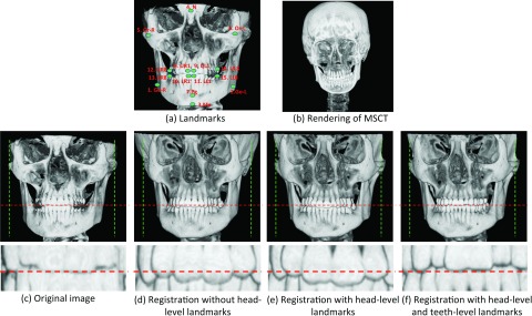
(a) Fifteen anatomical landmarks: #1–#15 are used to estimate the affine matrix to warp the atlases onto the testing subject; #8–#15 are used to estimate the affine matrix to warp the teeth joint regions between the template images and the testing image. (c) is the same as (a). (d) and (e) show the registration results without and with head-level landmarks, respectively. (f) shows the registration result with both head-level and teeth level landmarks.
Estimating a patient-specific atlas
Atlas-based segmentation has demonstrated its robustness and effectiveness in many medical image segmentation problems.33 Specifically, a population-based atlas, in the context of this work, is defined as the pairing of a template image and its corresponding tissue probability maps.34 The template image often refers to an intensity image, equally or weighted averaged from a number of aligned intensity images of the training subjects. Given a population-based atlas, image registration could be used to warp this atlas to the query image, to yield a transformation that allows the atlas's tissue probability maps to be transformed and treated as tissue probabilities for the query subject. However, a population-based atlas often fails to provide useful guidance, especially in the regions with high intersubject anatomical variability, thus leading to unsatisfactory segmentation results [Fig. 5b]. One way to overcome this problem is to integrate the patient-specific information35, 36, 37 in the atlas construction. To this end, we propose to construct a patient-specific atlas by combining both population and patient information as detailed below.
Figure 5.
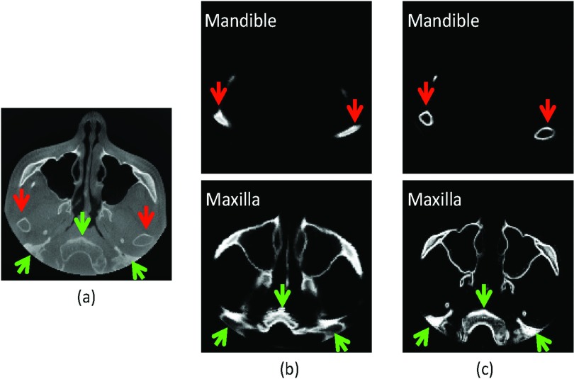
(a) Original image. Comparison between population-based atlas (b) and patient-specific atlas (c). The proposed patient-specific atlas produces a more accurate estimation than the population-based atlas, especially in the regions indicated by the arrows.
Specifically, we propose to estimate the patient-specific atlas by using a patch-based representation technique.38, 39 The rationale is that an image patch generally provides richer information, e.g., anatomical pattern, than a single voxel. First, N intensity images of atlases Ij(j = 1, …, N) and their corresponding segmentations Sj are aligned onto the space of the testing image I according to the registration method described in Sec. 2.B. Then, for each voxel χ in the testing image I, its corresponding intensity patch with size of w × w × w can be represented as a column vector Q(χ). Similarly, at the same location, we can obtain patches Qj(χ) from the jth aligned atlas. An initial codebook B can be constructed using all these atlas patches, i.e., B(χ) = [Q1(χ), Q2(χ), …, QN(χ)]. To alleviate the effect of possible registration errors, the initial codebook B is extended to include more patches from the neighboring search window (i.e., a w′ × w′ × w′ cubic) of all N aligned atlases, thus generating an overcomplete codebook with superior representation capacity.40 In the codebook B(χ), each patch is represented by a column vector and normalized with unit ℓ2 norm.40, 41 To represent the patch Q(χ) by the codebook B(χ), its coding vector c could be estimated by many coding schemes, such as vector quantization, locality-constrained linear coding,42 and sparse coding.43, 44 In this paper, we utilize the sparse coding scheme43, 44 to estimate the coding vector c by minimizing a non-negative Elastic-Net problem,45
| (1) |
where the first term is the least square fitting term, the second term is the ℓ1 regularization term used to enforce the sparsity constraint on the reconstruction vector c, and the last term is the ℓ2 smoothness term used to enforce the similarity of coding coefficients for similar patches. Equation 1 is a convex combination of ℓ1 lasso46 and ℓ2 ridge penalty, which encourages a grouping effect while keeping a similar sparsity of representation.45 Each element of the coding vector c, i.e., cj(y), reflects the similarity between the target patch Q(χ) and the patch Qj(y) in the codebook. Based on the assumption that the similar patches should share similar labels, we use the sparse coding c to estimate the prior probability of the voxel χ belonging to the ith structure/region (e.g., mandible, maxilla, soft-tissue, or background), i.e.,
| (2) |
where Z is a normalization constant to ensure , and δi(Sj(y)) = 1 if the label Sj(y) = i; otherwise, δi(Sj(y)) = 0. By visiting each voxel in the testing image I, we can finally build a patient-specific atlas pi. The constructed patient-specific atlas for the image shown in Fig. 5a is provided in Fig. 5c, which captures more accurate patient-specific anatomical structures than the traditional population-based atlas [Fig. 5b], which was constructed using Joshi et al.'s groupwise registration method.47 Finally, the patient-specific atlas can be used as a prior to accurately guide the subsequent level-sets based segmentation.
Convex segmentation based on MAP
The patient-specific atlas could provide a rough segmentation if simply thresholding the priori probability for each voxel. However, it may result in spatially inconsistent segmentation since the patient-specific atlas is estimated in a voxelwise manner. Moreover, in the construction of the patient-specific atlas, it is difficult to enforce the geometrical constraints, e.g., no overlapping between mandible and maxilla. To address these issues, we propose the following strategy to integrate the patient-specific atlas into a level-set framework based on the maximum a posteriori probability rule.
Specifically, to accurately label each voxel χ in the image domain Ω of the testing image, we jointly consider its neighboring voxels , where is the neighborhood of voxel χ. In fact, we can use a Gaussian kernel Kρ with scale ρ to control the size of the neighborhood .48 The regions {Ωi} produce a partition of the neighborhood , i.e., . We first consider the segmentation of based on maximum a posteriori probability. According to the Bayes rule:
| (3) |
where , denoted by pi,χ(I(y)), is the structure probability density in region . Note that p(y ∈ Ωi), i.e., pi(y), is the a priori probability of y belonging to the region Ωi, which has been estimated in Sec. 2B. Note that the prior probability was not utilized in the previous work49 (all partitions were assumed to be equally possible) and only population-based probability was utilized.50 is the indicator function, and p(I(y)) is independent of the choice of the region and can therefore be neglected. Accordingly, Eq. 3 can be simplified as
| (4) |
Assuming that the voxels within each region are independent, the MAP will be achieved only if the product of pi, χ(I(y))pi(y) across the regions is maximized: . Taking a logarithm transformation and then integrating all the voxels χ, the maximization can be converted to the minimization of the following energy:
| (5) |
In this way, multiple level set functions could be used to represent the regions {Ωi} as in the work of Li et al.48 However, the minimization problem with respect to the level set function is usually a nonconvex problem and there is a risk of being trapped in the local minima. Alternatively, based on the work of Goldstein and Bresson,51 multiple variables could be used by taking values between 0 and 1 to derive a convex formulation. Since, in our project, there are only three different regions of interest: mandible, maxilla, and background, we need just two segmentation variables u1 ∈ [0 1] and u2 ∈ [0 1] to represent the partitions {Ωi}:M1 = u1,M2 = u2,M3 = (1 − u1)(1 − u2). Therefore, we convert Eq. 5 as follows:
| (6) |
There are many options to estimate pi, x(I(y)). In this paper, we utilize a Gaussian distribution model with the local mean μi(x) and the variance (Ref. 52) to estimate it:
| (7) |
Based on the assumption that there should be no overlap between mandible and maxilla, we propose the following penalty constraint term:
| (8) |
In addition, the length regularization term53 is defined as the weighted total variation of functions u1 and u2,
| (9) |
where g is a nonedge indicator function that vanishes at object boundaries.53
Finally, we define the entire energy functional below, which consists of the data fitting term , the overlap penalty term , and the length regularization term :
| (10) |
where α and β are the positive coefficients. Based on Ref. 51, the energy functional in Eq. 10 can be easily minimized in a fast way with respect to u1 and u2.
EXPERIMENTAL RESULTS
Evaluation metrics
In the following, we mainly employ Dice ratio to evaluate the segmentation accuracy, which is defined as
where A and B are two segmentation results of the same image. We also evaluate the accuracy by measuring the average surface distance error, which is defined as
where surf(A) is the surface of segmentation A, nA is the total number of surface points in surf(A), and dist(a, B) is the nearest Euclidean distance from a surface point a to the surface B.
Parameter optimization
The parameters in this paper were determined based on 30 MSCT subjects via cross-validation. For example, we tested the weight for ℓ1-term λ1 = {0.01, 0.1, 0.2, 0.5}, the weight for ℓ2-term λ2 = {0, 0.01, 0.05, 0.1}, the patch size w = {5, 7, 9, 11, 13}, and the size of neighborhood w′ = {3, 5, 7, 9}. We then compare the sum Dice ratios of mandible and maxialla with respect to the different combinations of these parameters, and found that the best accuracy is achieved with the parameter λ1 = 0.1, λ2 = 0.05, w = 9, w′ = 5. Cross-evaluation was also performed to determine other parameters, such as ρ = 3 for the Gaussian kernel Kρ, and the weights α = 10 for the overlap penalty term and β = 10 for the length regularization term . Empirically, we found the performance of our algorithm is insensitive to the small perturbation of these parameters. However, the above range for each parameter was empirically chosen in our experiments, which could lead to local minimum results as we will discuss later.
Atlas selection
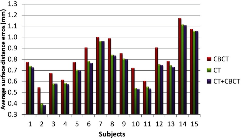
In this section, we evaluate the performance of segmentation accuracy using different sets of atlases, i.e., using (1) 15 CBCT subjects (excluding the testing one), (2) 30 MSCT subjects, and (3) 15 CBCT + 30 MSCT subjects (excluding the testing one) as atlases. The Dice ratios on mandible and maxilla, and the average surface distance errors on mandible, with respect to different sets of atlases, are shown in Figs. 67, respectively. It can be seen that the use of CBCT atlases alone result in slightly lower Dice ratios and higher surface distance errors than those obtained using spiral MSCT atlases. One reason may be due to the limited number of CBCT atlases. It is not surprising that the combination of MSCT and CBCT achieves the highest Dice ratios and also the smallest surface distance errors, due to inclusion of more atlases. Therefore, in this paper, we finally choose CBCT+ MSCT as the atlases.
Figure 6.

Evaluation of Dice ratios on mandible and maxilla with respect to different sets of atlases: 15 CBCT subjects (excluding the testing one), 30 MSCT subjects, and 15 CBCT + 30 MSCT subjects (excluding the testing one).
Figure 7.
Evaluation of average surface distance errors on mandible with respect to different sets of atlases: 15 CBCT subjects, 30 MSCT subjects, and 15 CBCT + 30 MSCT subjects.
Number of atlases vs accuracy
In the following, we explore the relationship between the number of atlases and the segmentation accuracy. Figure 8 shows the Dice ratios as a function of the number of atlases. As we can see, increasing the number of atlases generally improves the segmentation accuracy, as the average Dice ratio increased from 0.803 (N = 5) to 0.894 (N = 44) for mandible, and 0.732 (N = 5) to 0.855 (N = 44) for maxilla. However, the inclusion of more atlases would also bring in larger computational cost. Meanwhile, we found that, in our tests, when the number of atlases reaches 40, the performance of CBCT segmentation converges.
Figure 8.

Changes of Dice ratio of segmentation with respect to the number of atlases used. Experiment is performed by leave-one-out strategy on a set of 45 atlases.
Performance for the case of maximal intercuspation
As shown in Fig. 2b, due to the closed-bite position, the maxillary and mandibular teeth are touched to each other, which makes the automatic segmentation very difficult to achieve, as mentioned in the Introduction. To demonstrate the importance of employing the landmark-guided region-specific registration for separation of the maxillary (upper) and mandibular (lower) teeth, we first show the comparison results of the proposed method (Step 1: estimation of the patient-specific atlas) without and with landmark guidance for the teeth region in Fig. 9. The surface distance errors between the manual segmentations and automatic segmentations are calculated for better comparison. We also rotate the upper and lower teeth in different directions for a better visualization of the opened mouth. It can be clearly seen that the proposed method with the landmark-guided registration produces much more accurate results than that without landmark guidance. To show the advantage of the convex formulation in segmentation, we further show the result of the proposed method with both Step 1 (estimation of the patient-specific atlas) and Step 2 (convex segmentation) in the third column of Fig. 9. The average surface distance errors for the mandibular teeth and the maxillary teeth on 15 subjects are plotted in Fig. 10, which clearly demonstrates the advantage of the landmark-guided registration in estimation of the patient-specific atlas and the subsequent convex segmentation.
Figure 9.
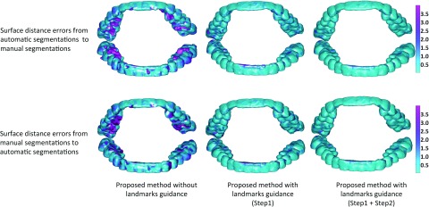
Comparison of results by the proposed method without or with landmark guidance.
Figure 10.
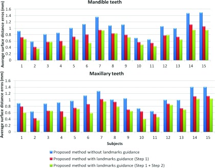
Average surface distances between the surfaces obtained by three different settings of our method and the manual segmented surfaces, on 15 subjects in the teeth joint regions.
Comparisons with the state-of-the-art methods
We first demonstrate the performance of different methods for the cases with maximal intercuspation [shown in Figs. 2b, 2c] in Fig. 11. We compare with other multi-atlases-based automatic segmentation methods,38, 39, 54, 55 using majority voting scheme, and conventional patch-based method.39 Note that, for a fair comparison, we perform a similar cross-validation as in Sec. 3.B to derive the optimal parameters for the CPM, thus obtaining finally the patch size of 9 × 9 × 9 and the neighborhood size of 5 × 5 × 5. The segmentation results on a selected slice and two surfaces by different methods are shown in the first and second rows, respectively. It can be seen that the proposed method successfully delineates the maxillary and mandibular teeth. We further calculate the surface distance errors between the manual segmentations and automatic segmentations in the fourth and fifth rows, which demonstrates that the proposed method achieves the best accuracy. Note that, for fair comparison, the results from the proposed method were directly derived from the patient-specific atlas (Step 1) by simple thresholding, similar to the CPM.
Figure 11.
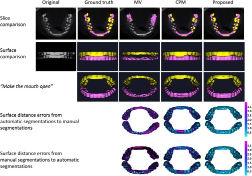
Segmentation results of three different methods for the case with maximal intercuspation. The first and second rows show the comparison on slice and surfaces, respectively. In the third row, we rotate the upper teeth and lower teeth to virtually make the mouth open for better visualization. The last two rows show the surface distance errors by three different methods.
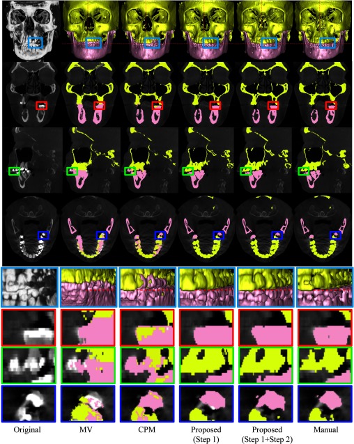
We then demonstrate the performance of different methods on a typical subject as shown in Fig. 12. In the first row, from left to right show the volume rendering of the original intensity image, and the surfaces obtained by MV, CPM,39 the proposed method by directly using the maximum class probability from Step 1 (prior estimation) as segmentation result, the proposed method with both Step 1 (prior estimation) and Step 2 (convex segmentation), and the manual segmentation. For better visualization, the corresponding results on slices and zoomed views are also provided in the bottom rows. Due to the errors in image registration process, the surface by MV is far from accurate, due to incorrect labeling of some upper teeth as lower teeth. Due to closed-bite position and the large intensity variations, the patch-based fusion method39 cannot accurately separate the mandible from maxilla, thus mislabeling the upper teeth and lower teeth. Overall, the proposed method produces much more reasonable results.
Figure 12.
Comparison of segmentation results by four different methods on a typical CBCT image. Note that the fourth row shows the segmentation of four different methods on the image shown in Fig. 1b.
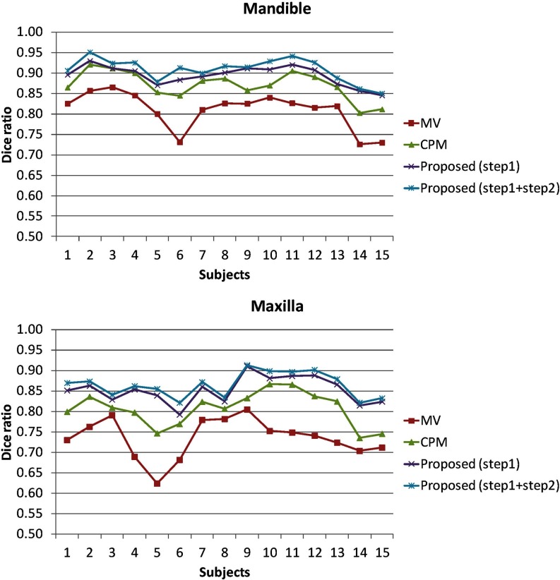
We finally use Dice ratio to quantitatively evaluate the overlap ratio between manual segmentations and automatic segmentation on 15 subjects, as shown in Fig. 13 and Table 1. As can be observed, by integrating both patient-specific atlas and convex segmentation, the proposed method achieves the highest Dice ratios. The upper row of Fig. 14 shows the surface distances from the surfaces obtained by these methods to the manual segmented surfaces, and the lower row shows the surface distances from the manual segmented surfaces to the automatically segmented surfaces. As can be seen from Fig. 14, the proposed method achieves superior results over all other methods. The average surface distance errors on 15 subjects are plotted in Fig. 15. Additionally, the Hausdorff distance
was also used to measure the maximal surface-distance errors of each of 15 subjects. The average Hausdorff distance on all 15 subjects are shown in Table 2, which again demonstrates the advantage of our proposed method.
Figure 13.
Dice ratios of segmented mandible and maxilla by four different methods on 15 CBCT subjects.
Figure 14.
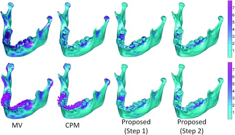
The upper row shows the surface distances in mm from the surfaces obtained by four different methods to the manual segmented surfaces. The lower row shows the surface distances from the manual segmented surfaces to the surfaces segmented by four different methods.
Figure 15.
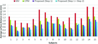
Average surface distances from the surfaces obtained by four different methods to the manual segmented surfaces on 15 subjects.
Table 2.
Average Dice ratios and surface distance errors (in mm) on 15 subjects (The best performance is indicated in boldface).
| MV | CPM (Ref. 39) | Proposed (Step 1) | Proposed (Step 1+2) | ||
|---|---|---|---|---|---|
| Dice ratio | Mandible | 0.82 ± 0.04 | 0.88 ± 0.02 | 0.90 ± 0.03 | 0.92 ± 0.02 |
| Maxilla | 0.74 ± 0.05 | 0.82 ± 0.03 | 0.86 ± 0.02 | 0.87 ± 0.02 | |
| Average distance error | Mandible | 1.30 ± 0.33 | 0.87 ± 0.25 | 0.72 ± 0.20 | 0.65 ± 0.19 |
| Hausdorff distance error | Mandible | 3.71 ± 1.68 | 2.45 ± 1.43 | 1.25 ± 0.62 | 0.96 ± 0.53 |
DISCUSSIONS
Normal subjects vs patients
The success of applying spiral MSCT atlases of the normal subjects to the CBCT images of the patients with CMF deformity can be mainly attributed to the following two factors: (1) The deformation between the subject with CMF deformity and the normal subject is first alleviated by the image registration; (2) After registration, the probabilities for the CBCT subject with CMF deformity are then robustly estimated by the proposed patch-based sparse technique in Sec. 2.C.
Image quality between MSCT and CBCT
Although the quality is different between MSCT and CBCT, the influence of the image quality is minimized due to the following reasons. First, our method works on image patches, where similar local patterns can be captured although the whole images may have large contrast differences. Second, in the following sparse representation, all the patches are normalized to have the unit ℓ2-norm to alleviate the intensity scale problem.40, 41 Third, the testing patch from CBCT can be well represented by the overcomplete patch dictionary constructed from the MSCT, as they share the same patterns of anatomical structures (e.g., the bones generally have high intensities while the soft tissues have low intensities).
Patch-based sparse representation vs conventional patch matching method
The conventional patch-based matching methods38, 39, 56, 57, 58 are less dependent on the accuracy of registration and this technique has been successfully validated on brain labeling38 and hippocampus segmentation39 with promising results. However, these methods38, 39, 56, 57, 58 mainly use a simple intensity difference based similarity measure (Sum of the Squared Difference, SSD). Consequently, they are sensitive to the variance of tissue contrast and luminance, which is often viewed in CBCTs. By contrast, in the proposed method, we assume that image patches can be represented by sparse linear combination of image patches in an overcomplete dictionary. It is a representation problem instead of a directly patch-matching problem as in Refs. 38 and 39. In the proposed method, all the patches are normalized to have the unit ℓ2-norm to alleviate the variance of tissue contrast and luminance.40, 41 The testing patch is well represented by the overcomplete patch dictionary with the sparse constraint. The derived sparse coefficients are utilized to (1) measure the patch similarity, instead of directly using the intensity difference similarity as used SSD in Refs. 38 and 39 and (2) estimate a patient-specific atlas, instead of a population-based atlas.
Computational cost
In our implementation, we use the LARS algorithm,59 which was available in the SPAMS toolbox (http://spams-devel.gforge.inria.fr), to solve the Elastic-Net problem. The average computational time is around 5 h for segmentation of a 400×400×400 image with a spatial resolution of 0.4 mm isotropic voxel on a linux server with 8 CPUs and 16G memory. In our future work, we will further optimize the code to reduce the computational time.
Summary
We proposed a new method for automatic segmentation of CBCT images. We first estimated a priori probability from spiral MSCT atlases by using a sparse label fusion technique. Then, the priori probability was integrated into a convex segmentation framework based on MAP. Comparing to the state-of-the-art label fusion methods, our method achieved more accurate segmentation results. In our future work, we will validate the proposed method on more subjects and will also improve its robustness by increasing the variability of the atlases, such as including more training subjects with different CMF deformities.
ACKNOWLEDGMENTS
The authors would like to thank the editor and anonymous reviewers for their constructive comments and suggestions. This work was supported in part by National Institutes of Health (NIH) Grant Nos. DE022676 and CA140413. The authors report no conflicts of interest in conducting the research.
References
- Loubele M., Bogaerts R., Van Dijck E., Pauwels R., Vanheusden S., Suetens P., Marchal G., Sanderink G., and Jacobs R., “Comparison between effective radiation dose of CBCT and MSCT scanners for dentomaxillofacial applications,” Eur. J. Radiol. 71, 461–468 (2009). 10.1016/j.ejrad.2008.06.002 [DOI] [PubMed] [Google Scholar]
- Schulze R., Heil U., Groβ D., Bruellmann D., Dranischnikow E., Schwanecke U., and Schoemer E., “Artefacts in CBCT: A review,” Dentomaxillofacial Radiol. 40, 265–273 (2011). 10.1259/dmfr/30642039 [DOI] [PMC free article] [PubMed] [Google Scholar]
- Loubele M., Maes F., Schutyser F., Marchal G., Jacobs R., and Suetens P., “Assessment of bone segmentation quality of cone-beam CT versus multislice spiral CT: A pilot study,” Oral Surg., Oral Med., Oral Pathol., Oral Radiol., Endodontol. 102, 225–234 (2006). 10.1016/j.tripleo.2005.10.039 [DOI] [PubMed] [Google Scholar]
- Li W., Liao S., Feng Q., Chen W., and Shen D., “Learning image context for segmentation of the prostate in CT-guided radiotherapy” Phys. Med. Biol. 57, 1283–1308 (2012). 10.1088/0031-9155/57/5/1283 [DOI] [PMC free article] [PubMed] [Google Scholar]
- Le B. H., Deng Z., Xia J., Chang Y.-B., and Zhou X., “An interactive geometric technique for upper and lower teeth segmentation,” in MICCAI 2009, Vol. 5762, edited by Yang G.-Z., Hawkes D., Rueckert D., Noble A., and Taylor C. (Springer, Berlin, 2009), pp. 968–975. [DOI] [PubMed] [Google Scholar]
- Shen D. and Ip H. H. S., “A Hopfield neural network for adaptive image segmentation: An active surface paradigm,” Pattern Recognit. Lett. 18, 37–48 (1997). 10.1016/S0167-8655(96)00117-1 [DOI] [Google Scholar]
- Zhan Y. and Shen D., “Automated segmentation of 3D US prostate images using statistical texture-based matching method,” in Medical Image Computing and Computer-Assisted Intervention - MICCAI 2003, Vol. 2878, edited by Ellis R. and Peters T. (Springer, Berlin, 2003), pp. 688–696. [Google Scholar]
- Hassan B. A., “Applications of cone beam computed tomography in orthodontics and endodontics,” Thesis, Reading University, VU University Amsterdam, 2010.
- Kainmueller D., Lamecker H., Seim H., Zinser M., and Zachow S., “Automatic extraction of mandibular nerve and bone from cone-beam CT data,” in MICCAI 2009, Vol. 5762, edited by Yang G.-Z., Hawkes D., Rueckert D., Noble A., and Taylor C. (Springer, Berlin, 2009), pp. 76–83. [DOI] [PubMed] [Google Scholar]
- Gollmer S. T. and Buzug T. M., “Fully automatic shape constrained mandible segmentation from cone-beam CT data,” in 9th IEEE International Symposium on Biomedical Imaging ISBI (IEEE, Barcelona, 2012), pp. 1272–1275.
- Suebnukarn S., Haddawy P., Dailey M., and Cao D., “Interactive segmentation and three-dimension reconstruction for cone-beam computed-tomography images,” NECTEC Tech. J. 8, 154–161 (2008). [Google Scholar]
- Duy N. T., Lamecker H., Kainmueller D., and Zachow S., “Automatic detection and classification of teeth in CT data,” in Medical Image Computing and Computer-Assisted Intervention – MICCAI 2012, Vol. 7510, edited by Ayache N., Delingette H., Golland P., and Mori K. (Springer, Berlin, 2012), pp. 609–616. [DOI] [PubMed] [Google Scholar]
- Duy N. T., “Automatic segmentation for dental operation planning,” Diploma thesis, Zuse Institut Berlin, 2013.
- Wang L., Shi F., Li G., Gao Y., Lin W., Gilmore J. H., and Shen D., “Segmentation of neonatal brain MR images using patch-driven level sets,” NeuroImage 84, 141–158 (2014). 10.1016/j.neuroimage.2013.08.008 [DOI] [PMC free article] [PubMed] [Google Scholar]
- Wang L., Shi F., Gao Y., Li G., Gilmore J. H., Lin W., and Shen D., “Integration of sparse multi-modality representation and anatomical constraint for isointense infant brain MR image segmentation,” NeuroImage 89, 152–164 (2014). 10.1016/j.neuroimage.2013.11.040 [DOI] [PMC free article] [PubMed] [Google Scholar]
- Gao Y., Liao S., and Shen D., “Prostate segmentation by sparse representation based classification,” Med. Phys. 39, 6372–6387 (2012). 10.1118/1.4754304 [DOI] [PMC free article] [PubMed] [Google Scholar]
- Elad M. and Aharon M., “Image denoising via sparse and redundant representations over learned dictionaries,” IEEE Trans. Image Process. 15, 3736–3745 (2006). 10.1109/TIP.2006.881969 [DOI] [PubMed] [Google Scholar]
- Mairal J., Elad M., and Sapiro G., “Sparse representation for color image restoration,” IEEE Trans. Image Process. 17, 53–69 (2008). 10.1109/TIP.2007.911828 [DOI] [PubMed] [Google Scholar]
- Winn J., Criminisi A., and Minka T., “Object categorization by learned universal visual dictionary,” in Tenth IEEE International Conference on Computer Vision, Vol. 2 (IEEE Computer Society, Beijing, 2005), vol. 1802, pp. 1800–1807.
- Yang J., Wright J., Huang T. S., and Ma Y., “Image super-resolution via sparse representation,” IEEE Trans. Image Process. 19, 2861–2873 (2010). 10.1109/TIP.2010.2050625 [DOI] [PubMed] [Google Scholar]
- Fadili M. J., Starck J. L., and Murtagh F., “Inpainting and zooming using sparse representations,” Comput. J. 52, 64–79 (2009). 10.1093/comjnl/bxm055 [DOI] [Google Scholar]
- Mairal J., Bach F., Ponce J., Sapiro G., and Zisserman A., “Discriminative learned dictionaries for local image analysis,” in Discriminative Learned Dictionaries for Local Image Analysis (CVPR) (IEEE Computer Society, Anchorage, AK, 2008), pp. 1–8. [Google Scholar]
- Zhang S., Zhan Y., Dewan M., Huang J., Metaxas D. N., and Zhou X. S., “Deformable segmentation via sparse shape representation,” in MICCAI 2011, Vol. 6892, edited by Fichtinger G., Martel A., Peters T. (Springer, Berlin, 2011), pp. 451–458. [DOI] [PubMed] [Google Scholar]
- Wang L., Chen K., Shi F., Liao S., Li G., Gao Y., Shen S., Yan J., Lee P. M., Chow B., Liu N., Xia J., and Shen D., “Automated segmentation of CBCT image using spiral CT atlases and convex optimization,” in Medical Image Computing and Computer-Assisted Intervention – MICCAI 2013, Vol. 8151, edited by Mori K., Sakuma I., Sato Y., Barillot C., Navab N. (Springer, Berlin, 2013), pp. 251–258. [DOI] [PMC free article] [PubMed] [Google Scholar]
- Gao Y., Zhan Y., and Shen D., “Incremental learning with selective memory (ILSM): Towards fast prostate localization for image guided radiotherapy,” in Medical Image Computing and Computer-Assisted Intervention – MICCAI 2013, Vol. 8150, edited by Mori K., Sakuma I., Sato Y., Barillot C., and Navab N. (Springer, Berlin, 2013), pp. 378–386. [DOI] [PMC free article] [PubMed] [Google Scholar]
- Shen D. and Davatzikos C., “HAMMER: Hierarchical attribute matching mechanism for elastic registration,” IEEE Trans. Med. Imaging 21, 1421–1439 (2002). 10.1109/TMI.2002.803111 [DOI] [PubMed] [Google Scholar]
- Zacharaki E. I., Shen D., Lee S.-k., and Davatzikos C., “ORBIT: A multiresolution framework for deformable registration of brain tumor images,” IEEE Trans. Med. Imaging 27, 1003–1017 (2008). 10.1109/TMI.2008.916954 [DOI] [PMC free article] [PubMed] [Google Scholar]
- Shen D., Wong W.-h., and Ip H. H. S., “Affine-invariant image retrieval by correspondence matching of shapes,” Image Vis. Comput. 17, 489–499 (1999). 10.1016/S0262-8856(98)00141-3 [DOI] [Google Scholar]
- Jia H., Wu G., Wang Q., and Shen D., “ABSORB: Atlas building by self-organized registration and bundling,” NeuroImage 51, 1057–1070 (2010). 10.1016/j.neuroimage.2010.03.010 [DOI] [PMC free article] [PubMed] [Google Scholar]
- Tang S., Fan Y., Wu G., Kim M., and Shen D., “RABBIT: Rapid alignment of brains by building intermediate templates,” NeuroImage 47, 1277–1287 (2009). 10.1016/j.neuroimage.2009.02.043 [DOI] [PMC free article] [PubMed] [Google Scholar]
- Thevenaz P. and Unser M., “Optimization of mutual information for multiresolution image registration,” IEEE Trans. Image Process. 9, 2083–2099 (2000). 10.1109/83.887976 [DOI] [PubMed] [Google Scholar]
- Klein S., Staring M., Murphy K., Viergever M. A., and Pluim J., “Elastix: A toolbox for intensity-based medical image registration,” IEEE Trans. Med. Imaging 29, 196–205 (2010). 10.1109/TMI.2009.2035616 [DOI] [PubMed] [Google Scholar]
- Aljabar P., Heckemann R. A., Hammers A., Hajnal J. V., and Rueckert D., “Multi-atlas based segmentation of brain images: Atlas selection and its effect on accuracy,” NeuroImage 46, 726–738 (2009). 10.1016/j.neuroimage.2009.02.018 [DOI] [PubMed] [Google Scholar]
- Shi F., Yap P., Wu G., Jia H., Gilmore J. H., Lin W., and Shen D., “Infant brain atlases from neonates to 1- and 2-year-olds,” PLoS One 6, e18746 (2011). 10.1371/journal.pone.0018746 [DOI] [PMC free article] [PubMed] [Google Scholar]
- Shi Y., Qi F., Xue Z., Chen L., Ito K., Matsuo H., and Shen D., “Segmenting lung fields in serial chest radiographs using both population-based and patient-specific shape statistics,” IEEE Trans. Med. Imaging 27, 481–494 (2008). 10.1109/TMI.2007.908130 [DOI] [PubMed] [Google Scholar]
- Feng Q., Foskey M., Tang S., Chen W., and Shen D., “Segmenting CT prostate images using population and patient-specific statistics for radiotherapy,” in IEEE International Symposium on Biomedical Imaging: From Nano to Macro, 2009 (ISBI’09) (IEEE, Boston, MA, 2009), pp. 282–285. [DOI] [PMC free article] [PubMed]
- Feng Q., Foskey M., Chen W., and Shen D., “Segmenting CT prostate images using population and patient-specific statistics for radiotherapy,” Med. Phys. 37, 4121–4132 (2010). 10.1118/1.3464799 [DOI] [PMC free article] [PubMed] [Google Scholar]
- Rousseau F., Habas P. A., and Studholme C., “A supervised patch-based approach for human brain labeling,” IEEE Trans. Med. Imaging 30, 1852–1862 (2011). 10.1109/TMI.2011.2156806 [DOI] [PMC free article] [PubMed] [Google Scholar]
- Coupé P., Manjón J., Fonov V., Pruessner J., Robles M., and Collins D. L., “Patch-based segmentation using expert priors: Application to hippocampus and ventricle segmentation,” NeuroImage 54, 940–954 (2011). 10.1016/j.neuroimage.2010.09.018 [DOI] [PubMed] [Google Scholar]
- Wright J., Yi M., Mairal J., Sapiro G., Huang T. S., and Yan S., –Sparse representation for computer vision and pattern recognition,– Proceedings of the IEEE 98, 1031–1044 (2010). 10.1109/JPROC.2010.2044470 [DOI] [Google Scholar]
- Cheng H., Liu Z., and Yang L., “Sparsity induced similarity measure for label propagation,” in IEEE 12th International Conference on Computer Vision (ICCV) (IEEE, Kyoto, 2009), pp. 317–324.
- Wang J., Yang J., Yu K., Lv F., Huang T. S., and Gong Y., “Locality-constrained linear coding for image classification,” in IEEE Conference on Computer Vision and Pattern Recognition (CVPR) (IEEE, San Francisco, CA, 2010), pp. 3360–3367.
- Wright J., Yang A. Y., Ganesh A., Sastry S. S., and Ma Y., “Robust face recognition via sparse representation.,” IEEE Trans. Pattern Anal. Mach. Intell. 31, 210–227 (2009). 10.1109/TPAMI.2008.79 [DOI] [PubMed] [Google Scholar]
- Yang J., Yu K., Gong Y., and Huang T., “Linear spatial pyramid matching using sparse coding for image classification,” in IEEE Conference on Computer Vision and Pattern Recognition (CVPR) (IEEE, Miami, FL, 2009), pp. 1794–1801.
- Zou H. and Hastie T., “Regularization and variable selection via the elastic net,” J. R. Stat. Soc., Ser. B 67, 301–320 (2005). 10.1111/j.1467-9868.2005.00503.x [DOI] [Google Scholar]
- Tibshirani R. J., “Regression shrinkage and selection via the lasso,” J. R. Stat. Soc., Ser. B 58, 267–288 (1996). [Google Scholar]
- Joshi S., Davis B., Jomier M., and Gerig G., “Unbiased diffeomorphic atlas construction for computational anatomy,” NeuroImage 23(Suppl. 1), S151–S160 (2004). 10.1016/j.neuroimage.2004.07.068 [DOI] [PubMed] [Google Scholar]
- Li C. M., Kao C. Y., Gore J. C., and Ding Z. H., “Minimization of region-scalable fitting energy for image segmentation,” IEEE Trans. Image Process. 17, 1940–1949 (2008). 10.1109/TIP.2008.2002304 [DOI] [PMC free article] [PubMed] [Google Scholar]
- Wang L., He L., Mishra A., and Li C., “Active contours driven by local Gaussian distribution fitting energy,” Signal Process. 89, 2435–2447 (2009). 10.1016/j.sigpro.2009.03.014 [DOI] [Google Scholar]
- Wang L., Shi F., Lin W., Gilmore J. H., and Shen D., “Automatic segmentation of neonatal images using convex optimization and coupled level sets,” NeuroImage 58, 805–817 (2011). 10.1016/j.neuroimage.2011.06.064 [DOI] [PMC free article] [PubMed] [Google Scholar]
- Goldstein T., Bresson X., and Osher S., –Geometric applications of the split Bregman method: Segmentation and surface reconstruction,– Journal of Scientific Computing 45, 272–293 (2010). 10.1007/s10915-009-9331-z [DOI] [Google Scholar]
- Brox T. and Cremers D., “On local region models and a statistical interpretation of the piecewise smooth Mumford-Shah functional,” Int. J. Comput. Vis. 84, 184–193 (2009). 10.1007/s11263-008-0153-5 [DOI] [Google Scholar]
- Caselles V., Kimmel R., and Sapiro G., “Geodesic active contours,” Int. J. Comput. Vis. 22, 61–79 (1997). 10.1023/A:1007979827043 [DOI] [Google Scholar]
- Wang H., Suh J. W., Das S. R., Pluta J., Craige C., and Yushkevich P. A., “Multi-atlas segmentation with joint label fusion,” IEEE Trans. Pattern Anal. Mach. Intell. 35, 611–623 (2013). 10.1109/TPAMI.2012.143 [DOI] [PMC free article] [PubMed] [Google Scholar]
- Sabuncu M. R., Yeo B. T. T., Van Leemput K., Fischl B., and Golland P., “A generative model for image segmentation based on label fusion,” IEEE Trans. Med. Imaging 29, 1714–1729 (2010). 10.1109/TMI.2010.2050897 [DOI] [PMC free article] [PubMed] [Google Scholar]
- Eskildsen S. F., Coupé P., Fonov V., Manjón J. V., Leung K. K., Guizard N., Wassef S. N., Østergaard L. R., and Collins D. L., “BEaST: Brain extraction based on nonlocal segmentation technique,” NeuroImage 59, 2362–2373 (2012). 10.1016/j.neuroimage.2011.09.012 [DOI] [PubMed] [Google Scholar]
- Bai W., Shi W., O’Regan D., Tong T., Wang H., Jamil-Copley S., Peters N., and Rueckert D., “A probabilistic patch-based label fusion model for multi-atlas segmentation with registration refinement: Application to cardiac MR images,” IEEE Trans. Med. Imaging 32, 1302–1315 (2013). 10.1109/TMI.2013.2256922 [DOI] [PubMed] [Google Scholar]
- Coupé P., Eskildsen S. F., Manjón J. V., Fonov V., and Collins D. L., “Simultaneous segmentation and grading of anatomical structures for patient's classification: Application to Alzheimer's disease,” NeuroImage. 59, 3736–3747 (2012). 10.1016/j.neuroimage.2011.10.080 [DOI] [PubMed] [Google Scholar]
- Efron B., Hastie T., Johnstone I., and Tibshirani R., “Least angle regression,” Ann. Stat. 32, 407–499 (2004). 10.1214/009053604000000067 [DOI] [Google Scholar]


