Abstract
Vitreoretinal surgery is associated with serious complications that can easily stem from excessive tissue manipulation forces while the forces required for such surgery are routinely well below human tactile sensation. Despite the critical need in this area, there is still no practical vitreoretinal instrument that can sense both the axial and transverse tool-to-tissue interaction forces with sub-mN accuracy. In this study, we present the conceptual design and optimization of a 3 degrees-of-freedom (DOF) force sensing micro-forceps as the next generation of our force sensing instruments. 4 fiber Bragg grating (FBG) strain sensors are integrated in the design to measure tool tip forces.
I. Introduction
In retinal microsurgery, manipulation of extremely delicate tissues is required, which are performed by applying very small forces that are well below human tactile sensation. While the majority of forces applied during in-vitro retinal manipulation in porcine cadaver eyes were found to be below 7.5 mN [1], application of beyond this limit can easily lead to serious complications such as iatrogenic retinal breaks [2–4], vitreous hemorrhage as well as subretinal hemorrhage [5]. Thus, force sensing instruments emerge as a critical need in vitreoretinal surgery for improving safety and better surgery outcomes.
There have been various studies proposing various force sensing solutions in microsurgery and minimal invasive surgery (MIS): Semiconductor strain gauges were used as force sensors on robotic microgrippers [6]. Utilizing the diffractive optical MEMS encoders, a force sensing silicon-nitride probe was built [7]. For laparoscopic instruments in MIS, a tri-axial force sensor was developed based on intensity-modulated fiber optic sensing [8]. A 6-DOF force sensing forceps was designed for MIS [9]. The sensor utilized 6 strain gauges mounted on a Steward platform. None of these approaches are applicable to vitreoretinal surgery due to challenging size and resolution requirements. A miniature 3-DOF force sensing microsurgical instrument with sub-mN resolution was developed by Berkelman et al. [10]. This strain gauge based force sensor was mounted on the handle of a microsurgical instrument by Jagtap et al [11]. However, when forces exerted during several vitreoretinal surgery tasks were measured in-vivo in rabbits, they were considerably higher than the results presented in [1]. This can be explained by the friction and other forces between the tool and the trocar, which can significantly attenuate or distort the propagation of the forces to the tissues inside of the eye. Therefore, a handle mounted force sensor is not practical for vitreoretinal surgery. With this motivation, a family of instruments with force sensing was developed at Johns Hopkins University, which can measure the force directly at the tool tip inside the eye. First, a 1-DOF force sensing tool [12], then a 2-DOF pick like instrument [13] were built with FBG sensors. The 2-DOF pick was also used in combination with the steady-hand robot [16]. This was followed by a manual pair of 2-DOF force sensing forceps [14], and a 2-DOF forceps that can be used with the steady-hand robot [15] since membrane peeling is mostly done with forceps.
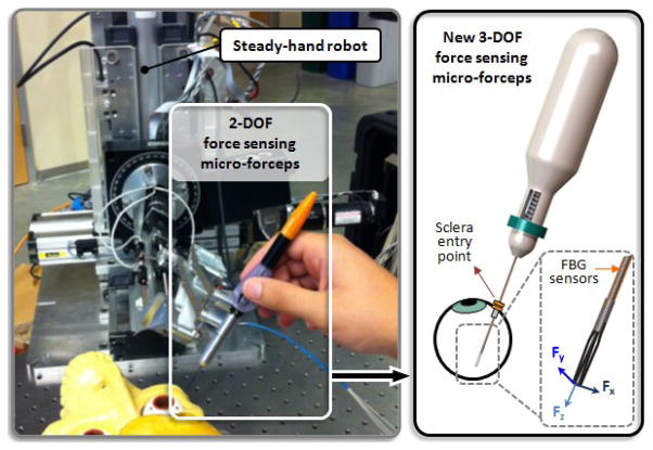
In this paper, we report the next step of our force sensing instruments: a 3-DOF force sensing forceps compatible with the steady-hand robot (Fig. 1). In the following sections, we will first present the conceptual design, and the optimization steps of our new tool. This will be followed by the simulation results of the optimal design and related force computation algorithm.
Figure 1.
Conceptual design of the Steady-Hand Robot compatible 3-DOF force sensing micro-forceps, which will replace the previously developed 2-DOF version.
II. Design
A. Force Sensing
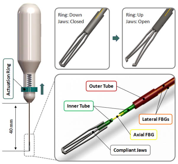
Accurate sensing of tool to tissue interactions in vitreoretinal surgery is an important but a significantly challenging task due to both form factor constraints and measurement resolution requirements. In order to measure forces applied solely at the instrument tip without any contribution from the sclerotomy site, the force sensor has to be functioning inside the eye close to the tool tip. This requirement implies several limitations in terms of availability of force sensing technologies: (1) the sensing tool should be thin so that it can be introduced into the eye through a ~25 Ga (max. 20 Ga) sclerotomy opening; (2) It has to be either inexpensive for a disposable design or sterilizable for multiple uses; (3) the sensor itself has to be biocompatible (not toxic or injurious to the eye) as it will be introduced into the eye during the surgery; (4) the measurements should have sub-mN accuracy since the forces associated with vitreoretinal microsurgery are routinely less than 7.5 mN. Under these limitations, using FBG strain sensors is a possible good option, and has revealed promising results in 2-D force sensing instruments so far [12–15]. In these designs, 3 FBGs were mounted around the tool shaft to sense transverse loading at the tool tip. In designing 3-DOF forceps we followed a similar approach. The transverse loading is still measured via the 3 (lateral) FBGs on the outer tube of the forceps. However, additionally, a 4th axial FBG is located in the central tube for measuring the axial forces. In this case, it is significantly challenging to make a disposable tool by having a detachable separate force sensing module as in [15]. For practical and fabrication based reasons, we focus on a reusable and sterilizable design. As shown in Fig. 2, the tubes carrying the lateral and axial FBGs are connected to each other via the inner and outer arms of the grasper jaws, which function as a flexure. Besides the grasping motion, an important duty of this flexure is the decoupling of forces so that the axial FBG remains insensitive to transverse loading. Similarly, due to design of the grasper jaws and the coupling with tubes, the strain on lateral FBGs is minimal in the presence of axial forces. Such axial-transverse force decoupling is accomplished through design optimization of the grasper jaws and verified through sensitivity analyses in the following sections.
Figure 2.
The mechanism and force sensing components: The outer tube (red) can be actuated by sliding the ring (blue) on the handle up to open the jaws. The outer tube carries 3 lateral FBGs (orange). There is a axial FBG (yellow) passing through the inner tube (green). The inner and outer tubes are connected via the compliant jaws (grey).
B. Grasping Mechanism
In designing forceps, there exist two main design approaches depending on the neutral position of the grasper jaws: a normally closed design vs. a normally open configuration. The forces of interest in vitreoretinal surgery are mainly the forces after the tissue is grasped. This requires the FBGs to be as much strain-free as possible while the jaws are closed. In our design, in order to reserve the limited strain range of FBGs only for tool-to-tissue interaction forces, and not to waste it by inner actuation forces, we preferred a normally closed design as shown in Fig 2.
The actuation of the forceps is accomplished by the relative motion of two concentric tubes that form the tool shaft. The inner and outer tubes carry the axial and lateral FBGs respectively, and are connected to each other via the inner and outer arms of the grasper jaws. The outer tube can be actuated by sliding the circular ring up and down. A spring with adjustable pre-tension helps keeping the jaws closed and modifying the grasping force as desired during use. Pulling the circular ring up opens the graspers, and when released the forceps is closed under the force applied by the pre-tension spring and the graspers’ own stiffness.
C. Optimization
The design of the graspers in our concept has a large impact on the induced strain on each tube, which is important for the decoupling of axial-transverse forces, and for better sensitivity. The compliance of the graspers also defines the actuation force. For easier operation and minimal inner stresses during use, it is desirable to minimize the actuation force - the required pulling force on the outer tube (Fig. 2). Minimum actuation force, complete decoupling and maximum sensitivity can simultaneously be obtained by designing very flexible graspers and using flexible inner-outer tubes. However, such a design would also make grasping and accurate tool positioning a real challenge. In addition, limited manufacturing capabilities and associated fabrication cost have to be considered in optimizing the design.
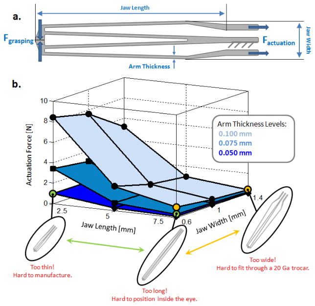
We optimized the jaws of our forceps under the goal of minimizing actuation force while preserving a minimum grasping force of 20 mN (without the pre-tension spring) and considering laser cutting limits. The material was specified as nitinol (SE508 from Nitinol Devices & Components, Inc.) for its super-elastic properties with a sheet thickness of 0.4 mm. The variable parameters involved in the design of our graspers are shown in Fig 3a. The effect of each parameter on the actuation force is presented in Fig. 3b, which is obtained by static analyses on 27 different designs in SolidWorks. Accordingly, increasing the jaw length, the jaw width and decreasing the arm thickness provide smaller actuation force. The effect of jaw length on the actuation force is most significant when greater arm thicknesses are considered while the jaw width is not critical especially for longer jaws. On the other hand, tuning all these parameters so as to minimize actuation force reduces the grasping force. For this reason, the minimum grasping force criterion defines a bound on these variables. In addition to functional requirements, the design variables are also limited by application based facts and manufacturing capabilities. The jaw length cannot be greater than 14 mm since the adult human eye ball is typically below 24 mm in diameter, 10 mm of which is already occupied by the active segment of FBGs. The jaw width cannot be increased too much since the instrument has to pass through a 20 Ga trocar (0.9 mm ID). However, this limit can be slightly exceeded as long as the tool can be squeezed to pass through the trocar without breaking. Finally, the links on the jaws cannot be thinner than 50 microns as smaller values would make laser cutting really challenging, or in some cases even impossible depending on the equipment available. Considering all of these, the optimal values of the design variables were selected as shown in Table I.
Figure 3.
(a) Design parameters to be optimized for minimal actuation force and a grasping force greater than 20 mN. (b) The effect of design parameters on actuation force and associated feasibility limits based on nitinol use (E=41 GPa, ν=0.33).
TABLE I.
Optimal Design Parameters
| Requirement | Optimal Value | |
|---|---|---|
| Arm Thickness | ≥ 0.050 | 0.075 mm |
| Jaw Width | ≈ 0.9 mm | 1 mm |
| Jaw Length | ≤ 14 mm | 5 mm |
| Actuation Force | Minimal | 0.7 N |
| Grasping Force | ≥ 20 mN | 20 mN |
The true scale deformation under 0.7 N of actuation force and the corresponding stress distribution of the optimal design is shown in Fig. 4a. The opening between the jaws ranges between 0–0.8 mm for forces between 0–0.7 N, which should be sufficient for grasping and peeling thin membraneous layers inside the eye. Another concern in forceps design is the life-time of the jaws. Being subject to cyclic loading during use, the jaws will eventually break due to fatigue. Both the magnitude and frequency of applied actuation forces is important in determining the life time of the instrument. Since most of the tool tip-to-tissue forces normally range between 0 and 10 mN [1], small damage is caused during tissue manipulation. The life limiting damage mainly stems from the opening and closing motion of the jaws. Shown in Fig. 4b is the total life of the optimal design considering an average actuation force of 1N. Accordingly, the instrument is expected to function for over 60,000 opening-closing cycles before failure. However, this approximate value will be lower with greater applied forcing and as a consequence of the wear and tear caused sterilization.
Figure 4.
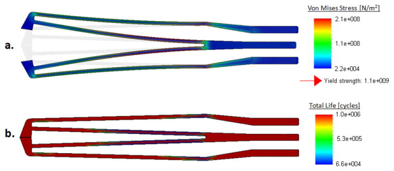
Optimal jaw design: (a) Stress distribution while opening the jaws, (b) Fatigue life under 1 N cyclic loading: more than 60,000 cycles of actuation cycles before failure based on nitinol use (E=41 GPa, ν=0.33).
III. Sensitivity and Characterization
A. Sensitivity Analysis
Simulations were done to determine the strain induced on each FBG under 3 loading cases using SolidWorks. The FBG configuration, axis directions, applied loads and resulting strains are shown in Fig. 5. When the loading was increased gradually, linearly increasing strain response was obtained, as expected. The slope of each line in this figure denotes the relative sensitivity of the associated FBG sensor with regard to the related loading case. When there is pure axial loading on the tool tip, almost no strain is induced on the lateral FBGs. Similarly, application of only transverse forces does not cause a significant variation in axial FBG strain. The slope values presented in Table II indicate that successful decoupling is accomplished via this jaw design.
Figure 5.
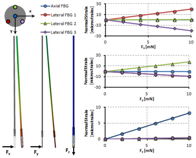
Induced normal strains on FBG sensors under various loading conditions. Linear rise in strain with greater forcing is observed for the affected sensors. Lateral FBGs are sensitive to pure transverse loading while axial FBG is affected only from axial forces.
TABLE II.
Sensitivity Analysis Results
| Sensitivities
[microstrain/mN] |
||||
|---|---|---|---|---|
| Forces | Axial FBG | Lateral FBG 1 | Lateral FBG 2 | Lateral FBG 3 |
| Fx | 0.0004 | 1.9925 | 0.0462 | −1.988 |
| Fy | −0.0127 | −0.9508 | 1.7985 | −0.9193 |
| Fz | 0.8169 | −0.0444 | 0.0413 | −0.0448 |
B. Force Computation
In actual use, a combination of the simulated forces in Fig. 5 will be acting on the tip. Based on the sensitivities in Table II, these forces can be computed directly from FBG readings. The measured wavelength shift for each FBG channel (λ) is related to the force induced normal strain (εF) and the temperature induced strain (εT) via equation (1):
| (1) |
The contribution from the ambient temperature variation can be eliminated by taking the average of all measurements and subtracting this mean value from the actual readings to form a new data set (Δλ) [13]. The linear relationship given by (2) gives the tip forces based on the force induced strain, where S is the sensitivity matrix formed based on the values in Table II, and S+ denotes its pseudoinverse:
| (2) |
The computed tip forces are then mapped into auditory signals to provide real-time auditory feedback to the surgeon. Such auditory sensory substitution gives a very clear cue on the applied forces even when they are well below human tactile threshold, and is an effective method for limiting forces in critical tasks such as membrane peeling [15,16].
IV. Conclusion
This paper has reported the conceptual design optimization of a 3-DOF force sensing micro-forceps for vitreoretinal surgery. Force sensing was provided by using 4 FBG sensors along the tool shaft. The active segments were located close to the distal end in order to sense only the tip forces. 3 FBGs located on the outer tube provided transverse loading information while a central FBG was used to measure axial forces. The decoupling between transverse and axial forces was accomplished by the design of grasper jaws as a compliant mechanism. The effect of various parameters involved in jaw design were analyzed, and optimal values were determined based on grasping force, actuation force, and various feasibility criteria. Simulations on the optimal design have revealed that the design targets have been met and successful force decoupling have been achieved.
Having optimized the design, we are currently in the phase of exploring fabrication alternatives. Upon fabrication and calibration of the tool, the performance will be compared with the simulation results presented in this paper. Our goal is to validate and compare both the hand-held and the Steady-Hand Robot assisted performance by conducting initially ex-vivo, and ultimately in-vivo experiments.
Footnotes
Research supported in part by the National Institutes of Health under R01 EB007969, R01 EB000526 and in part by Johns Hopkins internal funds.
Contributor Information
Berk Gonenc, Email: bgonenc1,rht@jhu.edu, CISST ERC at Johns Hopkins University, Baltimore, MD 21218 USA.
James Handa, Email: jthanda@jhmi.edu, Wilmer Eye Institute at The Johns Hopkins School of Medicine, Baltimore, MD 21287 USA.
Peter Gehlbach, Email: pgelbach@jhmi.edu, Wilmer Eye Institute at The Johns Hopkins School of Medicine, Baltimore, MD 21287 USA.
Russell H. Taylor, CISST ERC at Johns Hopkins University, Baltimore, MD 21218 USA.
Iulian Iordachita, Email: iordachita@jhu.edu, CISST ERC at Johns Hopkins University, Baltimore, MD 21218 USA.
References
- 1.Gupta P, Jensen P, de Juan E. Medical Image Computing and Computer-Assisted Intervention (MICCAI’99), vol. 1679 of Lecture Notes in Computer Science. Springer; Berlin/Heidelberg: 1999. Surgical forces and tactile perception during retinal microsurgery; pp. 1218–1225. [Google Scholar]
- 2.Sjaarda RN, Glaser BM, Thompson JT, Murphy RP, Hanham A. Distribution of iatrogenic retinal breaks in macular hole surgery. Ophthalmology. 1995 Sep;102(9):1387–1392. doi: 10.1016/s0161-6420(95)30859-7. [DOI] [PubMed] [Google Scholar]
- 3.Carter JB, Michels RG, Glaser BM, DeBustros S. Iatrogenic retinal breaks complicating pars plana vitrectomy. Ophthalmology. 1990 Jul;97(7):848–853. doi: 10.1016/s0161-6420(90)32492-2. [DOI] [PubMed] [Google Scholar]
- 4.Grigorian RA, Castellarin A, Fegan R, Seery C, Del Priore LV, von Hagen S, Zarbin MA. Epiretinal membrane removal in diabetic eyes: Comparison of viscodissection with conventional methods of membrane peeling. Br J Ophthalmology. 2003 Jun;87:737–741. doi: 10.1136/bjo.87.6.737. [DOI] [PMC free article] [PubMed] [Google Scholar]
- 5.Nakata K, Ohji M, Ikuno Y, Kusaka S, Gomi F, Tano Y. Sub-retinal hemorrhage during internal limiting membrane peeling for a macular hole. Graefes Arch Clin Exp Ophthalmol. 2003 Jul;241:582–584. doi: 10.1007/s00417-003-0676-y. [DOI] [PubMed] [Google Scholar]
- 6.Menciassi A, Eisinberg A, Scalari G, Anticoli C, Carrozza M, Dario P. Force feedback-based microinstrument for measuring tissue properties and pulse in microsurgery. Proc 2001 IEEE International Conference on Robotics and Automation. 2001:626–631. [Google Scholar]
- 7.Zhang X. Silicon microsurgery-force sensor based on diffractive optical MEMS encoders. Sensor Review. 2004;24(1):37–41. [Google Scholar]
- 8.Peirs J, Clijnen J, Reynaerts D, Van Brussel H, Herijgers P, Corteville B, Boone S. A micro optical force sensor for force feedback during minimally invasive robotic surgery. Sensors and Actuators A: Physical. 2004;115(2–3):447–455. [Google Scholar]
- 9.Seibold U, Kubler B, Hirzinger G. Prototype of instrument for minimally invasive surgery with 6-axis force sensing capability. Proc. 2005 IEEE International Conference on Robotics and Automation; 2005. pp. 496–501. [Google Scholar]
- 10.Berkelman PJ, Whitcomb LL, Taylor RH, Jensen P. A miniature microsurgical instrument tip force sensor for enhanced force feedback during robot-assisted manipulation. IEEE Trans Robotics and Automation. 2003 Oct;19(5):917–921. [Google Scholar]
- 11.Jagtap D, Riviere CN. Applied force during vitreoretinal microsurgery with handheld instruments. Proc. 26th IEEE engineering in medicine and biology conference (EMBS); San Francisco. 2004. pp. 2771–2773. [DOI] [PubMed] [Google Scholar]
- 12.Sun Z, Balicki M, Kang J, Handa J, Taylor R, Iordachita I. Development and preliminary data of novel integrated optical micro-force sensing tools for retinal microsurgery. Robotics and Automation. ICRA ‘09. IEEE Int. Conf; 2009. pp. 1897–1902. [Google Scholar]
- 13.Iordachita I, Sun Z, Balicki M, Kang J, Phee S, Handa J, Gehlbach P, Taylor R. A sub-millimetric, 0.25 mn resolution fully integrated fiber-optic force-sensing tool for retinal microsurgery. International Journal of Computer Assisted Radiology and Surgery. 2009;4:383–390. doi: 10.1007/s11548-009-0301-6. [DOI] [PMC free article] [PubMed] [Google Scholar]
- 14.He X, Balicki MA, Kang JU, Gehlbach PL, Handa JT, Taylor RH, Iordachita II. Force sensing micro-forceps with integrated fiber bragg grating for vitreoretinal surgery. Proceedings of SPIE; Feb, 2012. p. 82180W–82180W–7. [Google Scholar]
- 15.Kuru I, Gonenc B, Balicki M, Handa J, Gehlbach P, Taylor RH, Iordachita I. Force Sensing Micro-Forceps for Robot Assisted Retinal Surgery. Proc. International Conference of the IEEE EMBS (EMBC); San Diego, CA. Aug 28–Sep 1, 2012; pp. 1401–1404. [DOI] [PMC free article] [PubMed] [Google Scholar]
- 16.Balicki M, Uneri A, Iordachita I, Handa J, Gehlbach P, Taylor R. Micro-force Sensing in Robot Assisted Membrane Peeling for Vitreoretinal Surgery. Med Image Comput Comput Assist Interv. 2010;13(Pt 3):303–310. doi: 10.1007/978-3-642-15711-0_38. [DOI] [PMC free article] [PubMed] [Google Scholar]


