

Abstract
While fracture is generally considered to be undesirable in various manufacturing processes, delicate control of fracture can be successfully implemented to generate structures at micro/nano length scales. Fracture-based fabrication techniques can serve as a template-free manufacturing method, and enables highly-ordered patterns or fluidic channels to be formed over large areas in a simple and cost-effective manner. Such technologies can be leveraged to address biologically-relevant problems, such as in the analysis of biomolecules or in the design of culture systems that imitate the cellular or molecular environment. This mini review provides an overview of current fracture-guided fabrication techniques and their biological applications. We first survey the mechanical principles of fracture-based approaches. Then we describe biological applications at the cellular and molecular levels. Finally, we discuss unique advantages of the different system for biological studies.
1. Introduction
Advancements in micro/nano patterning and fabrication technology open new opportunities for the study of biological systems.1, 2 The vast majority of micro- and nanopatterning methods for such studies are achieved through the use of a template: a pre-fabricated hard structure, usually generated by various types of lithography, which is used to mold replicates or to spatially direct the chemical removal of material. Examples of these “template-assisted” methods include soft lithography,3, 4 hot embossing,5 etching,6 and nanoimprint lithography (NIL).7 In contrast, “template-free” patterning generates spatial patterns without the use of a pre-formed template structure to mold the final product.8 Examples of these approaches include cracking,9 wrinkling,10, 11 self-assembly,12 dip-pen lithography,13 and electro-spinning.14 In combination with biocompatible materials, these template-free fabrication methods are broadly applicable to biological studies, and may in some cases yield distinct advantages over template-assisted techniques in terms of simplicity, cost and utility. Such systems, when performed at the micro- and nano-scale are particularly useful in mimicking the cellular environment, and studying quantitative behaviors such as growth, signaling, migration, apoptosis, and differentiation in response to spatially-controlled extracellular matrices (ECM) at physiologically-relevant length scales.15, 16 In addition, these systems exploit control of size to enable biomolecular manipulation including sorting, separation, electrophoresis, and drug delivery.17–19 Recent work by us and others has focused on the use of fracture-based fabrication to develop surface patterns on substrates and to construct fluidic channels at micro- and nano- length scales. Fracture of materials is typically considered undesirable, as it is generally associated with failures. However, by controlling crack formation, it is possible to generate ordered micro/nano patterns over large areas, or flow channels after sealing, without expensive equipment. The fracture can be induced at different scales on a wide variety of materials from soft polymers to crystalline silicon and can mimic biological environments at cellular to single-molecule scales. In this brief review, we focus on surveying fracture-guided fabrication and its biological applications. We will first review the basic approach for fracture-based fabrication and then illustrate some biological applications at cellular and molecular levels.
2. Fracture-based fabrication
Crack formation in materials is controlled by (1) the mechanical properties, including modulus (stiffness of a material), toughness (energy required to break the material), and thermal expansion, (2) the geometrical properties (dimensions and flaw population), and (3) the loading (applied and residual strain, and temperature excursions). In this section, cracking mechanisms and fracture-based fabrications in the recent literature will be surveyed and discussed.
2.1 Fracture of thin films deposited on a substrate
In multi-layered materials, in which a modulus or toughness mismatch exists between the layers, arrays of stable cracks can form when the system is subject to tensile or compressive strains.9, 20–24 For example, the critical strain (εc) required to channel a crack across a film supported on a substrate is given by25, 26
where is the Young’s modulus of the film, Γf is the toughness of the film, h is the film thickness, and g (α, β) is a function of α, β, , the Dundur’s parameters reflecting the modulus mismatch between the film and substrate, showing the dimensionless quantity that represents the change in curvature of the film/substrate resulting from cracking. The critical strain increases as the thickness or the modulus of the film decreases. In other words, cracks form more easily when the deposited film is thicker and stiffer compared to the underlying substrate. A further increase in strain above the critical level results in arrays of cracks with a characteristic spacing inversely proportional to the applied strain as additional cracks are generated between the existing cracks.23, 24, 27, 28 These crack arrays are generally stochastic in nature, with a range of crack spacings and widths.29
In systems with a significant modulus mismatch between the film and substrate, the cracks can penetrate into the substrate,22, 24 and the crack dimensions are additionally influenced by the depth to which the cracks propagate below the film/substrate interface.24 Therefore, consideration of this effect is important when selecting appropriate materials for the film and substrate.
Work in our lab has centered around crack generation on the surface of the bio-compatible elastomer polydimethylsiloxane (PDMS).9, 22, 30–33 An intense plasma treatment creates an oxidized surface layer on the PDMS, which is stiffer and more brittle than the bulk material. Consequently, an array of parallel cracks form under an applied uniaxial strain above a threshold (Fig. 1a). Since PDMS is an elastomeric material, the widths of the cracks can be reversibly controlled by substrate stretching and relaxing. When the substrate contains an array of many cracks, the crack widths can be regulated down to the nanometer size scales by stretching or relaxing the bulk substrate at the millimeter scale. The cracked PDMS surface can be exploited to make tuneable nanofluidic systems by replica molding the crack patterns into another PDMS substrate and converting into a closed system by sealing another flat PDMS substrate against the cracks.30 Alternatively, nanochannels can be made in one step by stretching a brittle thin film sandwiched by elastomers on both sides.31, 34
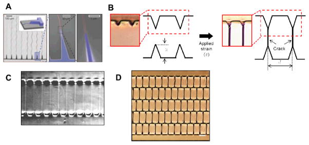
Figure 1. Schematics of fracture based fabrication technologies.

(A) Fracture on a thin film deposited on a substrate. Reprinted with permission from Zhu et al., Nature Materials., 4, 403, (2005). Copyright 2005 Nature Publishing Group. (B) Fracture induced formation of parallel silicone strips by peeling a thin silica film. Reprinted with permission from Cai et al., Journal Materials Research., 25, 803, (2010). Copyright 2010 Materials Research Society. (C) Fracture induced structuring (FIS) on a thin glassy layer. . Reprinted with permission from Pease et al., Nature Nanotechnology., 2, 546, (2007). Copyright 2007 Nature Publishing Group. ( (D) Fracture fabrication on a capillary. Reprinted with permission from Zhang et al., Microfluid Nanofluid 14, 69 (2013). Copyright 2013 Springer. (E) Fracture formation based on shrinkage of a polystyrene surface layer. Reprinted with permission from Xu et al., Lab Chip 10, 2894 (2010). Copyright 2010 The Royal Society of Chemistry.
An alternative fracture patterning method using oxidized PDMS was described by Cai et al.35 A PDMS membrane was directly exposed to UV/ozone to form a brittle, oxidized layer. The PDMS membrane was weakly bonded onto a silicon substrate. When the PDMS membrane was peeled away, periodic PDMS strips, formed by sequential cracking and detachment of the oxidized layer, remained on the substrate (Fig. 1b). A loss of adhesion at the interface between the PDMS membrane and the substrate occurred initially during peeling. Kinked cracks then grew bi-directionally along the peeling direction from the location of interfacial failure into the PDMS membrane. When the kinked crack encountered an adjacent kinked crack generated from the neighboring interfacial failure point, the PDMS membrane and the substrate were fully detached. Consequently, only a PDMS strip was left on the substrate. In this way, periodic triangular strips at the micron scale were constructed, the dimensions of which depend on the bending strain and the bonding strength of the involved materials.
A similar approach to produce periodic micro- and nanostructures by fracture on a glassy polymer was reported by Pease et al.36 A glassy polymer was first spin-cast onto a rigid plate to make a glassy thin film. Another rigid plate was then placed on top of the polymer film, resulting in a strongly bonded, sandwiched structure. Separation of the top layer from the sandwich induced two complementary sets of periodic gratings in the glassy film by fracture (Fig. 1c). Consequently, fracture-induced structuring (FIS) gratings were formed with regular periods, four times larger than the thickness of the glassy film. Provided the thin film is glassy, and is maintained below its glass transition temperature, broad periods ranging from 120 nm to 200 μm across centimeter square areas can be stably fabricated independent of molecular weight, chemical composition, and processing conditions of the glassy film. Similar fracture formation on a glass film are also found elsewhere.37–39
2.2 Fracture of glass capillaries
In addition to the fracture based techniques described above, it has recently been demonstrated that cracks initiated at a scratch site on a silica or glass capillary by gentle mechanical impact can be used for nanofluidic applications (Fig. 1d). Controlling the generation of cracks on the silica capillary is not easy because of the high modulus and because of the difficulty in establishing a termination point once a crack has begun. However, it has been shown that stress relieving or nanoporous materials can be used to generate nanofluidic structures on fracture. Wu et al. successfully demonstrated nanofabrication on silica capillary tubes.40 They first made a scratch at the center of a silica capillary coated with polyimide. The capillary was then connected to separate reservoirs, and the scratched region was either bent manually or sonicated, to partially fracture the material at the nanoscale. During the process, the polyimide coating played an important role of buffering the stress and preventing total failure of the silica capillary. Cracks smaller than 10 nm were directly revealed with SEM, and connectivity of each reservoir was confirmed by electric flow in an ionic solution.
A similar method was developed by Zhang et al, in which Nafion, a nanoporous resin, instead of the polyimide coating, was used to control cracking.41 Manually applied pressure was concentrated on a pre-existing scratch on the silica capillary, producing a fracture. Nafion resin solution was poured into the fracture area and cured at 95°C for 15 minutes. In order to avoid clogging within the capillary, a wire was loaded into it, and removed after the resin cured. Nanoscale fractures were confirmed using SEM. Similar to the work of Wu et al., each end as well as the fracture region in the capillary, was directly connected to independent reservoirs for further biological applications, as described in Section 3.
2.3. Fracture induced by shrinkage
Material shrinkage in layered structures can result in crack-inducing tensile strains. Using this effect, a lithography-free nanofabrication approach for polystyrene (PS) surfaces was developed by Xu et al.42 An ethanol solution in a commercially available PS petri-dish was heated to 80°C (i.e., above the boiling temperature of the ethanol, which is approximately 78°C). Evaporated ethanol was absorbed on the inner side of the PS petri-dish lid where it formed a swollen thin layer. When the petri dish was cooled, the absorbed ethanol was released and shrinkage of the inner surface occurred. The stress induced by shrinkage of the PS layer gave rise to parallel nanocracks following the anisotropic direction of PS chains within the petri-dish (Fig 1d). The cross sectional area of the nanocracks was controlled by parameters including temperature, solvent type, initial solvent volume, and crack growth time. The crack patterns were transferred to a polymer mold so that a replica could be made for further fabrication of nanofluidic systems.
3. Biological applications of fracture based micro- and nanofabrication
Fracture-based fabrication of micro- and nanofluidic channels is applicable to studying a variety of biological processes at various length scales. In this section, we survey the current uses of fracture to probe biology at the molecular and cellular levels.
3. 1. Cellular level
There are currently two broad arguments for the utility of fracture-based micro/nano fabrication technologies for cell and bacteria culture applications: manipulation of topography, and designing adhesive patterns.
First, cracked surfaces can influence cell function via topographically-driven mechanical-sensing mechanisms.43 While the effects of topography on cell function have been reviewed extensively elsewhere,44–46 cells sense both micro-scale and nano-scale topographical features, and these factors have been used to drive cellular alignment, protein expression and tissue maturation. While fracture-based fabrication has been used less frequently for these purposes than wrinkle-based fabrication approaches,47–51 this system has been applied to study the linked effects of surface chemistry, topography and elasticity of PDMS on the function of human mesenchymal stem cells (hMSCs).52
Second, crack-fabricated structures are useful as a simple and versatile method to rapidly and efficiently micropattern adhesive and non-adhesive areas on a cell culture substrate. In general, this patterning can be achieved by first rendering the oxidized PDMS surface to be non-adhesive, cracking the surface to expose fresh adhesive surfaces, and functionalizing the new surfaces with adhesive proteins or antibodies. Cells and bacteria cultured on these surfaces then selectively attach to the adhesive crack structures.
Developing a robust protocol to render the oxidized PDMS surface non-adhesive is a critical first step in utilizing this technology for micro/nano patterning applications. Zhu et al. and Dixon et al. achieved this by coating the freshly oxidized surface with (tridecafluoro-1,1,2,2-tetrahydrooctyl)-1-trichlorosilane by chemical vapour deposition at reduced pressures, and subsequently blocking non-specific protein adhesion by incubating the surface with Pluronic F108, an ethylene oxide/propylene oxide block copolymer.32, 53 Following the same principles, others have utilized vapour phase deposition of trichloro-(1H,1H,2H,2H-perfluoroctyl) silane to block antibody adhesion.54 Fracture can then be used to expose the underlying untreated surfaces. Cracks can be generated using either applied tension32 or compression,53, 55 and coated with candidate extracellular matrix proteins such as fibronectin, or with antibodies with highly specific binding sites.54 The surface crack structures can be reversibly widened and narrowed via externally applied strains and compressions. The dynamic tuneability of these cracks can be used to manipulate the dimensions of adhesive matrix protein arrays in real-time, by increasing or decreasing the applied tension. In this way, cells attach to protein patterns which change in size (Fig. 3a) and strain specific bacteria were adhered on the antibodies patterns (Fig. 3b). It was also demonstrated that cells can spread along single crack structures when the cracks are sufficiently wide, and that they retract and take on a more spherical morphology if the size of the cracks are reduced below this threshold. Hence, crack fabrication technologies may uniquely be used as a platform to study the dynamic effects of cell adhesion.
Figure 3. Applications of fracture based fabrication systems at a molecular level; DNA/chromatin linearization in nanochannels fabricated on a thin film.

(A) Normally closed nanochannels in oxidized PDMS. The nanochannels can be widen under an applied strain. Reprinted with permission from Mills et al., Lab Chip 10, 1627 (2010). Copyright 2010 The Royal Society of Chemistry. (B) Full length linearization of lambda DNA linearization in tuneable nanochannels. (C) Muti-color mapping of epigenetic markers of histone-H3K9me3 or histone-H4Ac on the elongated chromatin. Reprinted with permission from Matsuoka et al., Nano Lett., 12, 6480, (2012). Copyright 2012 American Chemical Society.
Micropatterning linear crack structures may also be applied to prompt cells to produce a “three-dimensional” (3D) response. Cells are typically cultured on flat, two-dimensional (2D) surfaces, such as tissue culture plastic or conventional Petri dishes. However, recent findings indicate that the three-dimensional nature of most in vivo cellular environments directs cells to function in a manner distinct from 2D cultures. This paradigm is of particular significance in drug screening applications, in which in vitro culture models must adequately represent cells in vivo, in order to generate clinically translatable results.56, 57 Several recent reviews emphasize the importance and challenges associated with 3D culture systems.58, 59 Such challenges include the increased cost and operational complexity of using 3D biomaterials, the difficulties in extracting biological samples for analysis, and the experimental challenges associated with decoupling confounding biological effects.60, 61
A potentially promising approach to address these challenges was recently demonstrated in a study by Doyle et al., in which cells were cultured on stripes of adhesive and non-adhesive regions.62 The linear micropatterns consisted of, adhesive regions that were narrower than the cells themselves. Although described as 1D cultures, these linear adhesive sites were found to prompt cells to function in a manner similar to cells cultured in 3D environments, in terms of cell morphology, migration and protein expression.62 The results suggest that these linear systems replicate important aspects of 3D structures from the perspective of cell functionality. As the crack-based fabrication methods outlined in this review were first utilized to generate “1D” adhesive lines,32 this approach has the potential for continued development as a technique for rapid and easy creation of “1D” culture substrates that could recreate 3D functionality. As an example, Dixon et al. recently took advantage of the fracture-based patterning approach using compression to rapidly generate cell culture surfaces that may simulate 3D culture systems.53 Cells grown on micropatterned adhesive cracks showed similarities in cytoplasmic and nuclear morphology to cells cultured in 3D systems. However, cells cultured on the linear 1D patterns are relatively simple to image, extract and probe using various analytical techniques that are challenging to implement in 3D. Hence, fracture-based micropatterning may provide a simple mechanism with which to pattern micron-scale and sub-micron scale linear features for further studies in cell dimensionality.
3.2. Molecular level
a. DNA/Chromatin linearization
One of the most important potential applications of fracture-fabricated nanofluidic channels is the confinement and elongation of coiled molecules for analytical purposes.63–65 Nucleic acid is a basic biological component containing important genetic information that eventually determines organism phenotypes. In the natural state of DNA, the molecule is randomly coiled and actively interacts with histone proteins forming a more complex structure known as chromatin. The coiling and uncoiling of DNA is a critical process in regulating cell function. Gene expression is strongly affected by interactions between DNA and histones in response to cell environments, in a process we now conceptualize as epigenetic changes. Hence, analyzing the structure of DNA/histone complexes is critical in understanding how epigenetic mechanisms regulate cell function. Structural rearrangements of DNA and chromatin are induced in confinements below the radius of gyration of long-chain molecules. Nanoconfinement and elongation of DNA/chromatin can be used to infer genetic information by “direct reading” of the elongated strand with the help of intercalating dyes into DNA, rather than by individual base pair sequencing.34, 64, 66 Thus, the nanoconfinement may offer a suitable platform to increase our understanding about the physical properties of DNA as a polymer.65 Fracture-based nanochannels have been exploited to trap and stretch both DNA and chromatin. As described, the unique capabilities of fracture-based fabrication using the PDMS elastomer enables the reversible modulation of channel dimensions, by changing the strain applied to the device (Fig. 4a).31 This tuneablility of the channels is particularly advantageous in uncoiling DNA/chromatin, as it allows easy sample loading of the coiled DNA when the channel is held open. The DNA/chromatin can then be linearized as the channels are allowed to close. Using normally-closed nanofluidic channels where channel narrowing occurs upon the release of an externally applied strain,31, 34 a nanoscale squeezing flow can be generated as fluid is forced out of the nanochannels. The simultaneous effects of elongational shear flow and nanoconfinement have been demonstrated to stretch lambda DNA up to its full contour length in a physiologically-relevant buffer solution (Fig. 4b).34
Figure 4. Silica capillary systems for bio-molecular studies.

(A) Electrokinetic stacking of DNA molecules in nanofracture on fused silica microchannels. Fluorescence image of the stacked DNA in the capillary (left). Theoretical schematic of the DNA stacking (right). Reprinted with permission from Wu et al., Lab Chip 12, 3408 (2012). Copyright 2012 The Royal Society of Chemistry
Similarly, chromatin extracted from HeLa cells was elongated for multi-color histone mapping in the nanochannels.34 Nanofluidics provide a suitable platform for reliable elongation of chromatin, so that epigenetic makers can be directly observed in relation to the rest of the DNA/chromatin complex. As in the case of the lambda DNA elongation, the open nanochannels have large enough dimensions to allow the chromatin to be introduced. Since coiled chromatin is generally much larger than DNA strands, loading chromatin into nanochannels efficiently is particularly difficult using conventional nanofluidics. In addition, the dual effects of the nanoconfinement and squeezing flow generated as the channels close provide a force large enough to stretch the labeled chromatin, but not enough to break the chromatin structures. With treatments of fluorescently-labeled antibodies that target histone modifications, multiple sites including H3K9me3 and H4Ac, and DNA were imaged from individual strands of elongated chromatin (Fig. 4c).34 Based on these maps, gene activation and de-activation regions could be distinguished, opening the potential to perform systematic and quantitative analysis of epigenetic markers on linearized chromatin. Hence, biologically meaningful changes of epigenetic conditions in different cell types or in different cell states may be studied using fracture-based nanofluidic systems.
b. Pre-concentration of biomolecules
Miniaturized chemical and biochemical reactors can be designed using micro/nanofluidics. Such reactors may provide significant advantages over conventional systems in reducing required sample volumes and reaction times resulting from high area to volume ratios. In particular, nanofluidic structures enable enrichment of charged biomolecules using the unique ionic conditions formed at this length scale.
The efficient pre-concentration of biomolecules is necessary for many biological analyses, where low concentrations of target molecules are beyond the detection limits of the tools available. Several approaches for pre-concentration have been developed using micro/nanofluidics, such as amplified sample stacking, isoelectric focusing, electric field, temperature gradient, and electrokinetic trapping.67–69 Regardless of these benefits, the adoption of such technology is limited, particularly by biologists, because expensive tools and highly-specific expertise are typically required to fabricate such nano-structures. Hence, fracture can be a good alternative to create the nanostructures in a rapid and easy way.30–32, 34, 35, 40, 41, 53, 54, 70–72
Crack-based fabrication technologies have successfully been employed to create biomolecule concentrators based on an exclusion-enrichment effect.40, 41, 72 When a charged surface is exposed to an ionic solution, an electrically neutral thin layer, referred to as the ‘electric double layer’ (EDL), forms at the surface.73 In general, the size of the EDL is approximately 1 to 10 nm in common ionic solvents. The exclusion-enrichment effect occurs under conditions where the size of the nanochannel is less or equal to a thickness of EDL and leads to considerably altered transportation of charged molecules through the channel. Molecules with the same charge as the surface are excluded from the channel, whereas molecules with an opposing charge are enriched due to electrostatic attraction. In this sub-section, we will review how pre-concentration of biomolecules has been accomplished in fracture-based fabrication systems.
DNA pre-concentration
The exclusion enrichment effect can also be applied to pre-concentrate DNA that is typically diluted in large volumes of liquid. Wu et al. demonstrated lambda DNA pre-concentration in the nanofluidics fabricated by the direct mechanical impact on a silica capillary.40 As described in section 2.3, a nanofracture was developed in the middle of the silica capillary (Fig. 6a).41 Each end of the silica capillary was connected to DNA reservoirs, and electrically grounded. The middle portion of the device was linked to a buffer solution reservoir and coupled to an electrical anode. When the applied voltage is high, an EDL formed as the fused silica surface became negatively charged with Si-OH groups. Overlapping EDLs at the nanocrack site enabled selective attraction of ions in the solution. The negatively charged lambda DNA in the reservoirs connected to each end was electrokinetically driven through the channel and prevented from passing through the nanocrack area, where it was stacked and concentrated. The DNA was amplified ~105 times in 7 min under optimized conditions where the applied voltages were suppressed enough not to induce negative effects (Fig. 6b). 40 Identical approaches have also been demonstrated using nanofluidics combined with an ion exchange polymer resin enabling lambda DNA concentration by a factor of 103 in just 15s.41
4. Conclusion and perspectives
Controlled micro and nanopatterns are attractive for biological experiments because of the enhanced precision and degree of quantification they make possible at the length scale of single cells and biomolecules. Recent advances make some procedures of cracking attractive as an alternative approach to conventional template-assisted fabrication. Such fracture-based fabrication provides the ability to rapidly create micro/nano patterns on a large scale, without expensive equipment, facilities or highly-specific expertise. These advantages of fracture-based fabrication allow non-experts in micro-engineering to access micro/nano technologies, because cracking requires little special equipment and is based more on careful choice of intrinsic material properties and consideration of the mechanical stresses applied.
Nevertheless, the inherent randomness associated with cracking makes precise control of the crack dimensions challenging.29 Some approaches have been developed recently that can overcome such limitations to regulate crack propagation at pre-designed positions. For example, Nam et al. and Kim et al. incorporated intentional defects or stress-shielding structures into multilayered systems to initiate cracks at pre-defined locations (Fig. 5a–b).70, 71 Nam et al. used Si3N4 on a stiff silicon wafer (Fig. 5a) while Kim et al. used an oxidized layer (oxidized PDMS/PDMS, Fig. 5c) or a thin metal film layer (gold/PDMS, Fig. 5d) on elastomeric polymer substrates. While the methods of Nam et al. and Kim et al. of introducing v-shaped features into a substrate to control cracking may look similar on the surface, Huang et al. recently discussed in detail the differences in mechanisms of crack formation and how the experimental design parameters for the v-shaped features and degree of strain must be adjusted depending on geometry and material properties.74 These works suggest a promising future for the use of cracking as a method to perform precise nano-fabrication.
Figure 5. Precision-control of crack positions with designed stress-concentrating or stress-shielding structures.
(A) Guided fracture formation initiated from micro-notches on a stiff silicon substrate. Reprinted with permission from Nam et al., Nature., 221, 485, (2012). Copyright 2012 Nature Publishing Group. (B) Schematics of controlled crack formation following pre-designed notches on a thin film deposited on a soft substrate. (C) Periodic cracking in an oxidized PDMS/PDMS substrate with saw-tooth. Reprinted with permission from Kim et al., Scientific Reports, 3, 3027, (2013). Copyright 2013 Nature Publishing Group. (D) Multiple brick stack structures generated by controlled cracking of an Au/PDMS bilayer.
Other challenges for biological studies include mechanical mismatch between biological materials that are often soft, pliable, and undergo dynamic structural changes versus readily cracked materials that are often brittle, hard, and rigid such as silicon, glass, or hard plastics. Further development of understanding the mechanics of cracking, together with experimental procedures that enable appropriate combinations of rigid and soft material systems together may expand opportunities for novel biological studies including dynamic regulation of cell-accessible adhesive surfaces, active filtration of particles and biological molecules, reversible biopolymer linearization, and flexible electronics.
In conclusion, advances in controlling cracking in diverse material systems from the nano- to micro- scales are envisioned to enable the production of more complex dynamic patterns, that will in turn drive broader applications in biological research.
Figure 2. Utility of fracture based fabrication as a micro/nano patterning technology for cell study.

(A) Cells cultured on the fracture patterned arrays exhibit elongated morphologies only under the applied strains . Reprinted with permission from Zhu et al., Nature Materials., 4, 403, (2005). Copyright 2005 Nature Publishing Group. (B) Strain specific bacterial adhesion on the patterned arrays for bacteria-based sensing applications. Reprinted with permission from Cao et al., J. Phys. Chem. B, 112, 2727 (2008). Copyright 2008 American Chemical Society.
Acknowledgments
This work was supported by a grant from the US National Institutes of Health (HG0063-03) and a Biointerfaces Institute Seed Grant. We gratefully acknowledge personal support to CM from the Banting and Natural Sciences and Engineering Research Council of Canada (NSERC) fellowship programs.
References
- 1.Chantiwas R, Park S, Soper SA, Kim BC, Takayama S, Sunkara V, Hwang H, Cho YK. Chemical Society Reviews. 2011;40:3677–3702. doi: 10.1039/c0cs00138d. [DOI] [PMC free article] [PubMed] [Google Scholar]
- 2.Pan T, Wang W. Annals of biomedical engineering. 2011;39:600–620. doi: 10.1007/s10439-010-0218-9. [DOI] [PMC free article] [PubMed] [Google Scholar]
- 3.Whitesides GM, Ostuni E, Takayama S, Jiang X, Ingber DE. Annual review of biomedical engineering. 2001;3:335–373. doi: 10.1146/annurev.bioeng.3.1.335. [DOI] [PubMed] [Google Scholar]
- 4.Rogers JA, Nuzzo RG. Materials today. 2005;8:50–56. [Google Scholar]
- 5.Becker H, Gärtner C. Electrophoresis. 2000;21:12–26. doi: 10.1002/(SICI)1522-2683(20000101)21:1<12::AID-ELPS12>3.0.CO;2-7. [DOI] [PubMed] [Google Scholar]
- 6.Mao P, Han J. Lab on a Chip. 2005;5:837–844. doi: 10.1039/b502809d. [DOI] [PubMed] [Google Scholar]
- 7.Chou SY, Krauss PR, Renstrom PJ. Journal of Vacuum Science & Technology B: Microelectronics and Nanometer Structures. 1996;14:4129–4133. [Google Scholar]
- 8.Rogers JA, Lee HH. Unconventional Nanopatterning Techniques and Applications. 2009:325–357. [Google Scholar]
- 9.Mills K, Zhu X, Takayama S, Thouless M. Journal of Materials Research. 2008;23:37–48. doi: 10.1557/JMR.2008.0029. [DOI] [PMC free article] [PubMed] [Google Scholar]
- 10.Chung S, Lee JH, Moon MW, Han J, Kamm RD. Advanced Materials. 2008;20:3011–3016. [Google Scholar]
- 11.Sun Y, Choi WM, Jiang H, Huang YY, Rogers JA. Nature Nanotechnology. 2006;1:201–207. doi: 10.1038/nnano.2006.131. [DOI] [PubMed] [Google Scholar]
- 12.Whitesides GM, Grzybowski B. Science. 2002;295:2418–2421. doi: 10.1126/science.1070821. [DOI] [PubMed] [Google Scholar]
- 13.Piner RD, Zhu J, Xu F, Hong S, Mirkin CA. Science. 1999;283:661–663. doi: 10.1126/science.283.5402.661. [DOI] [PubMed] [Google Scholar]
- 14.Schiffman JD, Schauer CL. Polymer Reviews. 2008;48:317–352. [Google Scholar]
- 15.Sia SK, Whitesides GM. Electrophoresis. 2003;24:3563–3576. doi: 10.1002/elps.200305584. [DOI] [PubMed] [Google Scholar]
- 16.El-Ali J, Sorger PK, Jensen KF. Nature. 2006;442:403–411. doi: 10.1038/nature05063. [DOI] [PubMed] [Google Scholar]
- 17.Dittrich PS, Manz A. Nature Reviews Drug Discovery. 2006;5:210–218. doi: 10.1038/nrd1985. [DOI] [PubMed] [Google Scholar]
- 18.Beebe DJ, Mensing GA, Walker GM. Annual review of biomedical engineering. 2002;4:261–286. doi: 10.1146/annurev.bioeng.4.112601.125916. [DOI] [PubMed] [Google Scholar]
- 19.Paguirigan AL, Beebe DJ. BioEssays. 2008;30:811–821. doi: 10.1002/bies.20804. [DOI] [PMC free article] [PubMed] [Google Scholar]
- 20.Li T, Suo Z. International Journal of Solids and Structures. 2006;43:2351–2363. [Google Scholar]
- 21.Li T, Huang Z, Xi Z, Lacour SP, Wagner S, Suo Z. Mechanics of Materials. 2005;37:261–273. [Google Scholar]
- 22.Douville NJ, Li Z, Takayama S, Thouless M. Soft Matter. 2011;7:6493–6500. [Google Scholar]
- 23.Thouless M. Journal of the American Ceramic Society. 1990;73:2144–2146. [Google Scholar]
- 24.Thouless M, Li Z, Douville N, Takayama S. Journal of the Mechanics and Physics of Solids. 2011;59:1927–1937. doi: 10.1016/j.jmps.2011.04.009. [DOI] [PMC free article] [PubMed] [Google Scholar]
- 25.Beuth J., Jr International Journal of Solids and Structures. 1992;29:1657–1675. [Google Scholar]
- 26.Beuth J, Klingbeil N. Journal of the Mechanics and Physics of Solids. 1996;44:1411–1428. [Google Scholar]
- 27.Thouless MD, Olsson E, Gupta A. Acta metallurgica et materialia. 1992;40:1287–1292. [Google Scholar]
- 28.Hutchinson J, Suo Z. Advances in applied mechanics. 1992;29:191. [Google Scholar]
- 29.Thouless M. Annual Review of Materials Science. 1995;25:69–96. [Google Scholar]
- 30.Huh D, Mills K, Zhu X, Burns MA, Thouless M, Takayama S. Nature materials. 2007;6:424–428. doi: 10.1038/nmat1907. [DOI] [PubMed] [Google Scholar]
- 31.Mills K, Huh D, Takayama S, Thouless M. Lab Chip. 2010;10:1627–1630. doi: 10.1039/c000863j. [DOI] [PubMed] [Google Scholar]
- 32.Zhu X, Mills KL, Peters PR, Bahng JH, Liu EH, Shim J, Naruse K, Csete ME, Thouless M, Takayama S. Nature materials. 2005;4:403–406. doi: 10.1038/nmat1365. [DOI] [PubMed] [Google Scholar]
- 33.Cheng MC, Leske AT, Matsuoka T, Kim BC, Lee J, Burns MA, Takayama S, Biteen JS. The Journal of Physical Chemistry B. 2013;117:4406–4411. doi: 10.1021/jp307635v. [DOI] [PMC free article] [PubMed] [Google Scholar]
- 34.Matsuoka T, Kim BC, Huang J, Douville NJ, Thouless M, Takayama S. Nano letters. 2012;12:6480–6484. doi: 10.1021/nl304063f. [DOI] [PMC free article] [PubMed] [Google Scholar]
- 35.Cai Y, Newby B-mZ. Journal of Materials Research. 2010;25:803–809. [Google Scholar]
- 36.Pease LF, Deshpande P, Wang Y, Russel WB, Chou SY. Nature Nanotechnology. 2007;2:545–548. doi: 10.1038/nnano.2007.264. [DOI] [PubMed] [Google Scholar]
- 37.Liang PY, Yang F, Lee S. Materials Chemistry and Physics. 2012;135:168–173. [Google Scholar]
- 38.Tang J, Kolliopoulou S, Tsoukalas D. Microelectronic Engineering. 2009;86:861–864. [Google Scholar]
- 39.Lin TC, Huang LC, Chou TR, Chao CY. Soft Matter. 2009;5:3672–3676. [Google Scholar]
- 40.Wu ZY, Li CY, Guo XL, Li B, Zhang DW, Xu Y, Fang F. Lab Chip. 2012;12:3408–3412. doi: 10.1039/c2lc40571g. [DOI] [PubMed] [Google Scholar]
- 41.Zhang DW, Zhang HQ, Tian L, Wang L, Fang F, Liu K, Wu ZY. Microfluidics and Nanofluidics. 2013;14:69–76. [Google Scholar]
- 42.Xu BY, Xu JJ, Xia XH, Chen HY. Lab on a Chip. 2010;10:2894–2901. doi: 10.1039/c005245k. [DOI] [PubMed] [Google Scholar]
- 43.Moraes C, Sun Y, Simmons CA. Integrative Biology. 2011;3:959–971. doi: 10.1039/c1ib00056j. [DOI] [PubMed] [Google Scholar]
- 44.Bettinger CJ, Langer R, Borenstein JT. Angewandte Chemie International Edition. 2009;48:5406–5415. doi: 10.1002/anie.200805179. [DOI] [PMC free article] [PubMed] [Google Scholar]
- 45.Hoffman-Kim D, Mitchel JA, Bellamkonda RV. Annual review of biomedical engineering. 2010;12:203. doi: 10.1146/annurev-bioeng-070909-105351. [DOI] [PMC free article] [PubMed] [Google Scholar]
- 46.Kim DH, Provenzano PP, Smith CL, Levchenko A. The Journal of cell biology. 2012;197:351–360. doi: 10.1083/jcb.201108062. [DOI] [PMC free article] [PubMed] [Google Scholar]
- 47.Lam MT, Clem WC, Takayama S. Biomaterials. 2008;29:1705–1712. doi: 10.1016/j.biomaterials.2007.12.010. [DOI] [PMC free article] [PubMed] [Google Scholar]
- 48.Lam MT, Huang YC, Birla RK, Takayama S. Biomaterials. 2009;30:1150–1155. doi: 10.1016/j.biomaterials.2008.11.014. [DOI] [PubMed] [Google Scholar]
- 49.Lam MT, Sim S, Zhu X, Takayama S. Biomaterials. 2006;27:4340–4347. doi: 10.1016/j.biomaterials.2006.04.012. [DOI] [PubMed] [Google Scholar]
- 50.Chan EP, Crosby AJ. Soft Matter. 2006;2:324–328. doi: 10.1039/b515628a. [DOI] [PubMed] [Google Scholar]
- 51.Guvendiren M, Burdick JA. Advanced healthcare materials. 2013;2:155–164. doi: 10.1002/adhm.201200105. [DOI] [PubMed] [Google Scholar]
- 52.Yang Y, Kulangara K, Lam RT, Dharmawan R, Leong KW. ACS nano. 2012;6:8591–8598. doi: 10.1021/nn301713d. [DOI] [PubMed] [Google Scholar]
- 53.Dixon AR, Moraes C, Csete ME, Thouless M, Philbert MA, Takayama S. Journal of Biomedical Materials Research. 2013;Part A doi: 10.1002/jbm.a.34814. [DOI] [PMC free article] [PubMed] [Google Scholar]
- 54.Cao T, Wang A, Liang X, Tang H, Auner GW, Salley SO, Ng KS. The Journal of Physical Chemistry B. 2008;112:2727–2733. doi: 10.1021/jp711070k. [DOI] [PubMed] [Google Scholar]
- 55.Uchida T, Mills K, Kuo CH, Roh W, Tung YC, Garner AL, Koide K, Thouless M, Takayama S. Langmuir. 2009;25:3102–3107. doi: 10.1021/la801986k. [DOI] [PMC free article] [PubMed] [Google Scholar]
- 56.Pampaloni F, Reynaud EG, Stelzer EH. Nature reviews Molecular cell biology. 2007;8:839–845. doi: 10.1038/nrm2236. [DOI] [PubMed] [Google Scholar]
- 57.Pampaloni F, Stelzer EH. Biotechnology and Genetic Engineering Reviews. 2009;26:117–138. doi: 10.5661/bger-26-117. [DOI] [PubMed] [Google Scholar]
- 58.Baker BM, Chen CS. Journal of cell science. 2012;125:3015–3024. doi: 10.1242/jcs.079509. [DOI] [PMC free article] [PubMed] [Google Scholar]
- 59.Schwartz MA, Chen CS. Science. 2013;339:402–404. doi: 10.1126/science.1233814. [DOI] [PubMed] [Google Scholar]
- 60.Moraes C, Simon AB, Putnam AJ, Takayama S. Biomaterials. 2013 [Google Scholar]
- 61.Raghavan S, Shen CJ, Desai RA, Sniadecki NJ, Nelson CM, Chen CS. Journal of cell science. 2010;123:2877–2883. doi: 10.1242/jcs.055079. [DOI] [PMC free article] [PubMed] [Google Scholar]
- 62.Doyle AD, Wang FW, Matsumoto K, Yamada KM. The Journal of cell biology. 2009;184:481–490. doi: 10.1083/jcb.200810041. [DOI] [PMC free article] [PubMed] [Google Scholar]
- 63.Douville N, Huh D, Takayama S. Analytical and bioanalytical chemistry. 2008;391:2395–2409. doi: 10.1007/s00216-008-1995-y. [DOI] [PubMed] [Google Scholar]
- 64.Matsuoka T, Kim BC, Moraes C, Han M, Takayama S. Biomicrofluidics. 2013;7 doi: 10.1063/1.4816835. [DOI] [PMC free article] [PubMed] [Google Scholar]
- 65.Reisner W, Pedersen JN, Austin RH. Reports on Progress in Physics. 2012;75:106601. doi: 10.1088/0034-4885/75/10/106601. [DOI] [PubMed] [Google Scholar]
- 66.Aguilar CA, Craighead HG. Nature Nanotechnology. 2013;8:709–718. doi: 10.1038/nnano.2013.195. [DOI] [PMC free article] [PubMed] [Google Scholar]
- 67.Wang YC, Stevens AL, Han J. Analytical chemistry. 2005;77:4293–4299. doi: 10.1021/ac050321z. [DOI] [PubMed] [Google Scholar]
- 68.Kim SJ, Song YA, Han J. Chemical Society Reviews. 2010;39:912–922. doi: 10.1039/b822556g. [DOI] [PMC free article] [PubMed] [Google Scholar]
- 69.Schoch RB, Han J, Renaud P. Reviews of Modern Physics. 2008;80:839. [Google Scholar]
- 70.Nam KH, Park IH, Ko SH. Nature. 2012;485:221–224. doi: 10.1038/nature11002. [DOI] [PubMed] [Google Scholar]
- 71.Kim BC, Toshiki M, Christopher M, Jiexi H, TMD, Shuichi T. Scientific Reports. 2013;3:3027. [Google Scholar]
- 72.Yu H, Lu Y, Zhou Y-g, Wang F-b, He F-y, Xia X-h. Lab on a Chip. 2008;8:1496–1501. doi: 10.1039/b802778a. [DOI] [PubMed] [Google Scholar]
- 73.Sparreboom W, Van Den Berg A, Eijkel J. Nature Nanotechnology. 2009;4:713–720. doi: 10.1038/nnano.2009.332. [DOI] [PubMed] [Google Scholar]
- 74.Huang J, Kim BC, Takayama S, Thouless M. Journal of Materials Science. 2013:1–14. doi: 10.1007/s10853-013-7700-3. [DOI] [PMC free article] [PubMed] [Google Scholar]