Abstract
Water repellency of hairy surfaces depends on the geometric arrangement of these hairs and enables different applications in both nature and engineering. We investigate the mechanism and optimization of a hairy surface floating on water to obtain its maximum load-carrying capacity by the free energy and force analyses. It is demonstrated that there is an optimum cylinder spacing, as a result of the compromise between the vertical capillary force and the gravity, so that the hairy surface has both high load-carrying capacity and mechanical stability. Our analysis makes it clear that the setae on water striders' legs or some insects' wings are in such an optimized geometry. Moreover, it is shown that surface hydrophobicity can further increase the capacity of a hairy surface with thick cylinders, while the influence is negligible when the cylinders are thin.
Keywords: hairy surfaces, superhydrophobicity, free energy analysis, load-carrying capacity
1. Introduction
Superior water-repellency of hydrophobic rough/hairy surfaces can be used for applications of lowering the adhesive force of water droplets on solid surfaces, reducing drag for microfluidic devices and marine vessels and so on [1,2]. Valuable inspirations for designing such surfaces have been provided by nature [3–7]. For example, the lotus leaf with two-level hierarchical pillar structures exhibits ultra-low adhesive force to water [8]. Water striders can move effortlessly on water because of the special setae structures on their legs [9,10]. Hairy layers on the surfaces of the legs and wings help some flying insects living in a humid environment to avoid being wetted by rain and other water surfaces they may encounter [11,12]. Some insects and fish spiders living in marine habitats are able to stay underwater for a long time with a thin layer of air along their hairy body surface, which enables their respiration underwater [13–15]. Research interest has been paid to achieve high load-carrying capacity of porous/hairy surfaces by rendering them superhydrophobic as inspired by nature. Marmur & Ras [16] pointed out that the load-carrying capacity of porous rafts can be improved by the micro/nano-scaled inner pores at the raft bottoms. Miniature boats fabricated from copper meshes rendered superhydrophobic have shown remarkable loading capacity [17,18]. Hydrophobic powders enable liquid marbles to float on water surfaces [19]. Superhydrophobic carbon fibre fabrics and nanocellulose aerogel membranes have also proved to be good cargo-carriers on water, even on oil for the latter [20,21].
Water-repellent properties of rough surfaces with pillars or pores have been much investigated. Special attention is being paid to the water-repellent property of surface structures made from thin hairs or fibres [22,23]. Schematics of a water strider's leg and a fly's wing covered by setae/hairs are shown in figure 1a,b, respectively. The setae/hairs provide resistance for the surface to getting wetted by water. Many researchers have tried to understand how the hairy structures render legs or wings of some insects water repellent from the point of view of surface physics and chemistry. Gao & Jiang [9] have carried out sessile water-drop measurements and shown that the water strider's legs are superhydrophobic (i.e. the wetting contact angle of water droplet approx. 168°). Experiments have found that the wings of the cranefly also exhibit superhydrophobicity [12]. It is pointed out that the superhydrophobicity of water striders' legs is due to the conjunction of the nano-grooved oriented setae and the wax on the leg surface [24]. While theoretical calculations [25,26] have shown that the maximum buoyant force of a thin rod does not change much with the increase in the surface hydrophobicity, Lee & Kim [27] and Su et al. [28] have clarified that superhydrophobicity plays more important roles in lowering the adhesion and energy dissipation during the locomotion of water striders on water. Moreover, it is argued that the flexibility of the water striders' legs also contributes to their super water-repellency [29–31].
Figure 1.
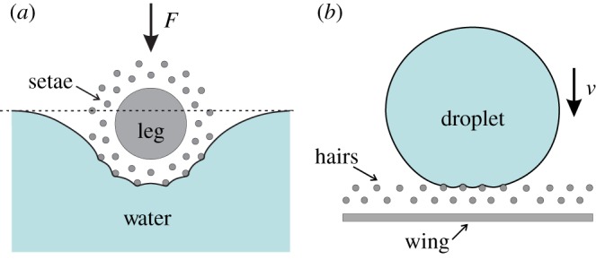
Schematics of the cross sections of (a) a water strider's leg surrounded by uniformly distributed setae and pressed against water by a load F, and (b) a fly's wing with hairs impacted by a droplet with a velocity ν. (Online version in colour.)
In general, the existing studies are mainly focused on the apparent effects of hairy structures on surface hydrophobicity, floating or adhesion property. In fact, water-repellency of hairy surfaces depends on the size, spacing and orientation of the hairs [32,33]. When those hairs/setae are brought into contact with water, a large number of micro-menisci are formed, which render insects' legs or wings water repellent for particular functions (e.g. maximum load-carrying capacity, low adhesion, drag reduction, plastron respiration, etc.). The morphology of the menisci depends on the interaction between nearby hairs. The supporting force given by these menisci resists the penetration of water [13–15]. To keep the water-repellency, the spacing between those hairs should be small so that the liquid–air interfaces can stand the highest impact they may experience in their living environment, according to the Young–Laplace equation. On the other hand, densely packed hairs near the surface decrease the area fraction of the air–water interface, which hinders hairy surfaces in their particular functions. Therefore, a structural optimization of those hairy surfaces is needed. For example, the higher the supporting force can be provided by those hairs per unit area, the smaller part of a water striders' leg or a fly's wing will be wetted during a stroke on water or impact by a droplet (figure 1a,b). However, to the best of authors' knowledge, till now the mechanism of the hair interaction and the influence on the water-repellency have hardly been discussed, nor has the optimization design of a hairy surface to achieve the maximum supporting force per unit area.
In this paper, by adapting a simplified model of a hairy surface made from parallel cylinders floating on water, we investigate the mechanism and optimization of its water-repellency by applying both free energy and force analyses, with the aim to achieve the maximum load-carrying capacity and mechanical stability. This paper is organized as follows. In §2, we describe the variation of the meniscus shape when quasi-statically changing the vertical position of the hairy surface. In §3, we calculate the free energy change with respect to a reference state. The applied force needed to balance the cylinders is derived by differentiating the total free energy change with respect to the displacement. Respective free energy and force contributions by the inside and outside cylinders are compared. In §4, for a hairy surface of a given size, we investigate its optimization design to obtain the maximum load capacity and mechanical stability. In §5, concluding remarks are given.
2. Meniscus shapes
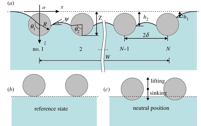
The buoyant force of an object floating on water is usually estimated by Archimedes' principle. When the size of the object is comparable to or much smaller than the capillary length  , where γ is surface tension, ρ density and g gravity acceleration), the effect of surface tension needs to be considered [34]. Although the hairs on water striders' legs are circularly distributed (figure 1a), for brevity but without losing the main physical picture, we consider a simple two-dimensional model in which a hairy surface made from N thin cylinders lying straightly parallel to each other is pressed against water, as shown in figure 2. Those cylinders are assumed to be rigid and hydrophobic.
Figure 2.
Schematic of a hairy surface made of N thin parallel cylinders floating on water under load: (a) current state, (b) reference state and (c) neutral position. (Online version in colour.)
A possible equilibrium state of the hairy surface under load is shown in figure 2a, in which the menisci formed along the boundary and inside cylinders protrude upward to resist sinking. The equilibrium state is available when the load is smaller than the load-carrying capacity of the hairy surface. The radius, length and spacing of those cylinders are denoted by R, L and 2δ, respectively. The width of the hairy surface is W (figure 2a). We assume L≫R so that a three-dimensional effect of the menisci is negligible. Here, θY is the Young contact angle, and θ1 and θ2 denote the half sector angles of the wetted outside and inside cylinders, respectively. Here and in the following, subscripts 1 and 2 refer to the outside and inside menisci/cylinders, respectively. We use Z to denote the displacement of the cylinders, and hi (i=1, 2) the position of the menisci with respect to a reference state, as shown in figure 2b, that is, the stationary state just before the bottom of the cylinders touches the water surface. We define a neutral position, where the menisci along the cylinders are horizontal (as shown in figure 2c).
Under the Cartesian coordinate system (o–xz) as shown in figure 2a, the balance between the Laplace pressure difference and the gravity potential gives the governing equations of the meniscus [35]:
| 2.1 |
Here, ψ is introduced as a geometric parameter. To present a general analysis, we introduce non-dimensional parameters
 |
2.2 |
where Bo is the Bond number [27]. With boundary conditions  ,
,  at the contact line, i.e. ψ=ψ2 (where ψi=θi+θY−π, i=1 and 2) and
  at ψ=0, we derive the expression for the inside meniscus
 |
2.3 |
where  and
and  , representing the incomplete elliptic integrals of the first and the second kinds, respectively. At the neutral position, we have ψi=0, i.e. θi=π−θY (i=1, 2). In equation (2.3), η is equal to 1 or −1. Here, η=1 represents the state of sinking, that is, the cylinders are pressed against water and the menisci protrude upward, i.e. ψi>0. On the other hand, η=−1 represents the state of lifting, that is, the cylinders are lifted up from water and the menisci sag downward, i.e. ψi<0 (figure 2c). Note that
  is related to
  by
by  , that is,
| 2.4 |
The parameter c2 is determined by
 |
2.5 |
For a given hairy surface, equation (2.4) expresses the dependence of θ2 on  or θ1. When combined with equation (2.4), equation (2.5) can be easily solved numerically to get θ2 and c2 for a given displacement
  of the raft. Then, the profile of the inside meniscus can be investigated based on equation (2.3).
With the assumption of small spacing between cylinders (i.e.  ), or small curvature variation along the meniscus, the expression for the inside meniscus (i.e. equation (2.3)) can be reduced and simply given by the Laplace equation that neglects the effects of gravity [13,15,16,36], that is,
| 2.6 |
where ΔP (=ρgh2) is the Laplace pressure difference across the meniscus and r is the constant curvature radius of the meniscus
 |
2.7 |
In the case of a small spacing, r and ψ2 determine the shape and position of the inside meniscus and can be resolved by equations (2.6) and (2.7).
When the spacing between nearby cylinders is much larger than the capillary length, i.e.  , the interaction between nearby cylinders becomes very weak and the inside and outside menisci exhibit a similar profile. Thus, the expression for the outside menisci can be obtained by equation (2.3) with
  , which leads to
 |
2.8 |
where
 |
2.9 |
and  . The analytical solution (2.8) has been obtained by Liu et al. [26]. The shape of the outside meniscus has been well investigated [26,35]. In the following, we focus on how the hair interaction influences the profile of the inside meniscus.
For most biological materials covered with smooth wax, θY has a value approximately 105° [9]. The Bond number of water striders' legs is approximately 1×10⁻³ and that of the setae on those legs is approximately 1×10⁻⁷ [9,37]. Here, we use an intermediate value of Bo=1×10⁻⁴ and θY=105° to illustrate the variation of the profile of the inside meniscus when the position of the raft is quasi-statically changed. Plots of θ2 as a function of  with respect to different θ1 are shown in figure 3. According to equation (2.4), θ1 uniquely represents the position of the raft: sinking when θ1>75° and lifting when θ1<75°. For the chosen values of θ1, the variation of θ2 shows a similar trend with the increase of
  : initially slight change around the neutral position (i.e. θ2=75°) when
  and then dramatic change until approaching a value close to θ1 when
  . A value of θ2 close to θ1 means that the interaction between the nearby cylinders becomes weak. At
  , we plot the profiles of the inside menisci for different positions during the sinking (e.g. θ1=100°, 130° and 160°) and lifting (e.g. θ1=60°, 30° and 0°) processes in figure 4. When sinking, the inside meniscus protrudes upward to balance the increased hydrostatic pressure; when lifting, the meniscus sags downward to resist lifting. With the profiles of the outside and inside menisci known, we will investigate the free energy and buoyant force of a hairy surface floating on water in §3.
Figure 3.
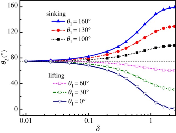
Plots of θ2 as a function of  with respect to different θ1 for Bo=1×10⁻⁴ and θY=105°. Sinking positions: θ1=100°, 130° and 160° and lifting positions: θ1=60°, 30° and 0°. The black dashed line shows the neutral position (i.e. θ2=75°). (Online version in colour.)
Figure 4.
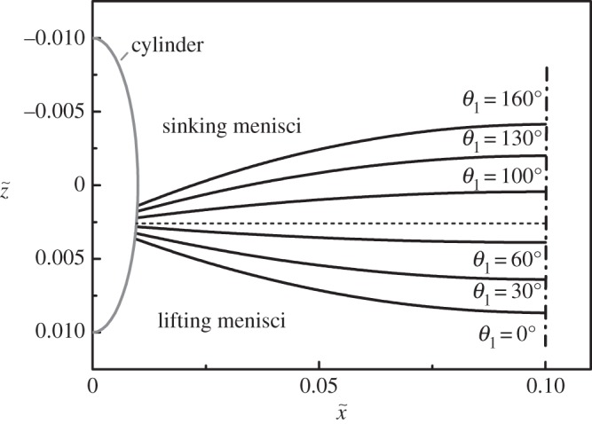
The profiles of the inside menisci at different positions: sinking (θ1=100°, 130° and 160°) and lifting (θ1=60°, 30° and 0°) for Bo= 1 × 10⁻⁴,  and θY=105°.
3. Free energy and buoyant force
The method of free energy analysis has been widely used to study the wetting phenomenon of liquid on solid surfaces [38–41]. For example, Rapacchiettta et al. [38] applied free energy analysis to study the interaction between a single cylinder and water surface. They compared the energy method with the force analysis method and demonstrated that the former is more comprehensive in displaying subtle characteristics of the systems. Lee & Kim [26] proposed a criterion for lifting a cylinder from water based on free energy analysis. Su et al. [28] calculated the energy dissipation of a cylinder by integrating the buoyant force with respect to the displacement. In this section, based on the meniscus profiles calculated in §2, we will calculate the free energy change of the system when quasi-statically changing the mechanically enforced stationary positions of the hairy surface, with respect to a reference state as shown in figure 2b. The free energy change is the energy barrier that the load needs to conquer before the surface reaches a certain position, or the negative work done by the buoyant force. A higher free energy change represents higher mechanical stability. Therefore, the buoyant force can be derived by differentiating the free energy change with respect to the displacement.
The total free energy of the system includes two parts: the surface free energy and gravitational potential energy. The energy E is non-dimensionalized by aLγ, i.e.  . The surface free energy associated with the outside menisci is expressed as
| 3.1 |
The surface free energy associated with each inside meniscus is expressed as
 |
3.2 |
The changes of the gravitational potential energy per cylinder, and the outside and inside menisci are denoted by  ,
,  and
and  , respectively,
| 3.3 |
 |
3.4 |
and
 |
3.5 |
where De is the ratio of the cylinder density ρs and the water density ρl. When the Bond number is small (e.g. Bo<0.01), the effect of cylinder's gravity is negligible. We choose De=1.2, which corresponds to the density of most biomaterials. Note that all the inside menisci are the same. The total free energy change of a hairy surface is given by
| 3.6 |
where  (
( ) and
) and  (
( ) are the free energies contributed by each outside and inside cylinders, respectively.
Figure 5 illustrates the diagrams of the free energy changes  and
and  at different stationary positions represented by θ1. Similar behaviour is found for both
  and
and  . At the neutral position, the free energy change is the lowest. Both the sinking and lifting of those cylinders increase the free energy change. The free energy difference with respect to the neutral position denoted by
  (
( , where
  is the free energy at the neutral position as shown in figure 2c) is the energy needed to sink or lift those cylinders to a certain position with respect to the neutral one. From figure 5, we can see that, as the surface hydrophobicity increases, while the sinking energy increases slightly, the lifting energy decays more pronouncedly. This means that a superhydrophonic cylinder can be lifted up from water much easier than a normally hydrophobic one. Our finding here is consistent with known concepts about the roles of surface hydrophobicity on the floating of a single cylinder on water [25–28].
Figure 5.
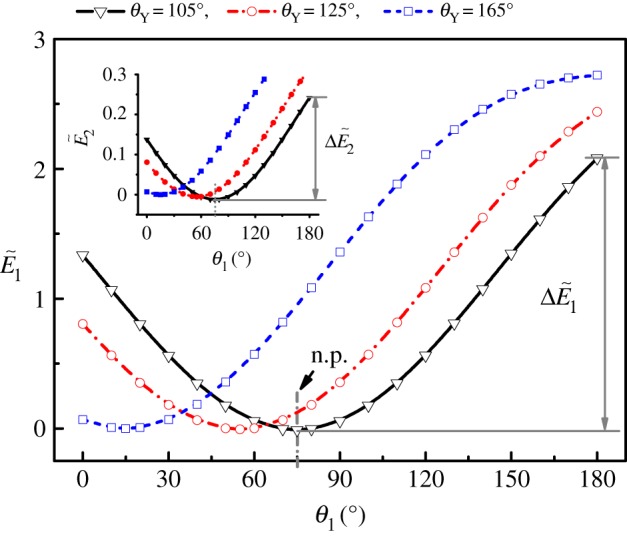
Diagram of the free energy change  at different stationary states for Bo=1×10⁻⁴,
  and different θY. The inset is the diagram of
  . The neutral position is denoted by ‘n. p.’, and
  and
and  are the free energy differences of the outside and inside menisci with respect to the neutral position, respectively. (Online version in colour.)
For a given hairy surface, the total sinking or lifting energy needed to put it at a certain position is equal to the negative work done by the buoyant force. With equations (2.4) and (3.6), we have
 |
3.7 |
Combination of equations (3.1)–(3.5) and (3.7) yields
 |
3.8 |
which is consistent with the results obtained from direct force analysis [16,25,26]. The detailed procedure to obtain equation (3.8) can be found in appendix A. Then, the total buoyant force is given by
| 3.9 |
It is interesting to see how the inside menisci contribute to the total free energy change and buoyant force during a sinking or lifting process of a hairy surface. This analysis in the following will be focused on the sinking process and the analysis of the lifting process can be obtained by following a similar procedure. During sinking, there is a position where the buoyant force generated by the outside menisci has a maximum value, i.e.  , which can be obtained by letting
  according to equation (3.8). This maximum value corresponds to the load-carrying capacity of the outside menisci. When the outside meniscus reaches the maximum load-carrying position, the inside meniscus is still quite stable, that is, the pressure difference across the meniscus is still much smaller than the maximum Laplace pressure that can be provided (i.e. equation (2.6)). As shown in figure 3, θ2 only approaches θ1 in the case of
  . Thus, it is reasonable to assume that the submersion of the whole hairy surface is generally induced by the collapse of the outside menisci. Therefore, we refer to the maximum load-carrying position of the outside cylinders as the maximum load-carrying position of the whole hairy surface, and the load-carrying capacity
  is a sum of
  and corresponding
  at this position, that is,
| 3.10 |
For Bo=1×10⁻⁴ and θY=105°, the maximum value of  is obtained at θ1∼165°. At this maximum load-carrying position, variations of
  and
and  with
with  are plotted in figure 6a,b, respectively. The values of
  and
and  are also included for comparison. It is seen that both
  and
and  increase with
  , and especially that the behaviours of both
  and
and  are approximately linear for small
  . When
  is small (e.g.
  ),
),  and
and  are one or even two orders of magnitude higher than
  and
and  , respectively. When
  is comparable with or even higher than 1, the interaction between the nearby cylinders becomes very weak and the contributions from the inside and outside cylinders are comparable. When
  , though the free energy and buoyant force contributions from each inside meniscus is much smaller than that of each outside meniscus, it can improve the total contribution of the inside menisci by increasing the cylinder numbers. For example, at
  , the values of
  and
and  are 0.20 and 0.28, respectively, and the values of
  and
and  are 1.73 and 2.01, respectively. With the number of the inside cylinder increased to 10, the contribution of the insider cylinders is already higher than that of the outside cylinder.
Figure 6.
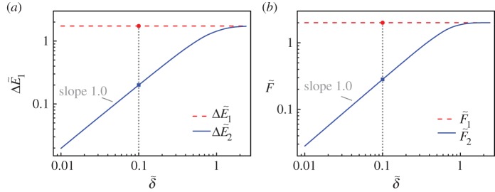
Variations of  (a) and
  (b) versus
  and respective comparisons with
  and
and  (Bo=1×10⁻⁴ and θY=105°). The dotted lines show the positions of
  . (Online version in colour.)
From the above analysis, it is shown that there are two ways to enhance the load-carrying capacity of a hairy surface: one by increasing the spacing between the cylinders of a constant number, as seen in figure 6, and the other by increasing the cylinder numbers while the cylinder spacing is kept constant. The former increases the vertical capillary force given by each inside meniscus, owing to the enhanced protrusion with a large spacing; the latter increases the total number of these menisci. However, both ways are limited by the overall size of the hairy surface. In §4, we will discuss how to obtain an optimum design for a hairy surface floating on water by adjusting the cylinder spacing.
4. Optimum design of hairy surfaces
As pointed out in §3, the maximum load-carrying position of a hairy surface is determined by the outside meniscus. Thus, for a given width and Bond number, the buoyant force produced by the outside menisci is fixed and the optimum design of a hairy surface can be obtained by adjusting the number and/or spacing of the cylinders. For the legs and wings of some insects (e.g. water striders, figure 1), it is meaningful to optimize the spacing between their setae so as to generate the maximum supporting force per unit area. Therefore, a smaller part of the legs will be wetted during a stroke when a water strider flees away and similarly, the contact area will also be smaller when the wing surface is impacted by a droplet (figure 1a,b). This will undoubtedly reduce the adhesion and energy dissipation during the movement of insects on water or flying in a very humid environment. On the other hand, for the design of a mini-raft of given width  , it is important to optimize the cylinder number for maximizing the load-carrying capacity of the raft. Note that
  (figure 2a). The total maximum load-carrying capacity given by the raft in equation (3.10) is obtained by an optimum design of the inside cylinders,
 |
4.1 |
From equation (4.1), we can see that the two optima, i.e. the optimum of the force per unit width and the optimum in the total force are consistent with each other. The optimum of the force per unit width generally leads to the optimum of the total force over a given width. Therefore, the study in the following sections is focused on the former optimum, i.e. maximizing  . As illustrated by equations (2.3) and (3.8),
  depends on the parameters
  , Bo and θY. Therefore, the optimum design of a hairy surface can be obtained by adjusting these parameters, as will now be discussed.
(a). Influence of hair spacing
We first investigate the dependence of  and
and  per unit spacing (i.e.
  and
and  ) on
) on  at the maximum load-carrying position (e.g. for θY=105°, θ1∼165°), which is plotted in figure 7 for three chosen Bond numbers (e.g. Bo=2.5×10⁻⁷, Bo=1.0×10⁻⁴ and Bo=1.0×10⁻²). As shown in figure 7a,b,
  and
and  show consistent results with each other: they both increase dramatically with the decrease of
  when
when  is large (e.g.
  ), reach a maximum and then decrease slightly with further decrease of
  when
when  is very small (e.g.
  ). It is seen that, for a large cylinder spacing, the inside meniscus protrudes upward significantly (see the inset 2 in figure 7a) and generates a vertical supporting force comparable with that of the outside meniscus (figure 6). For a small spacing, owing to the much smaller pressure difference across the meniscus than the maximum Laplace pressure that can be provided (see equations (2.6) and (2.7)), the meniscus is almost planar (see the inset 1 in figure 7a). Thus, the vertical supporting force given by each inside meniscus is negligible when compared with the outside meniscus (figure 6).
Figure 7.
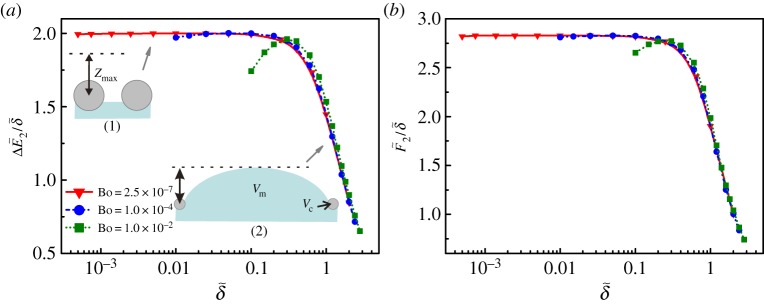
Dependence of  and
and  on
on  at the maximum load-carrying position with different Bond numbers (θY=105°). Insets in (a) represent the schematics of the inside meniscus at (1) small (e.g.
  ) and (2) large (e.g.
  ) spacings. Zmax in the insets denotes the displacement at the maximum load-carrying position. V
m and V
c are the volumes of the protruded meniscus and the cylinder, respectively. (Online version in colour.)
According to the generalized Archimedes' principle [34], the total buoyant force provided by the cylinders is proportional to the total volume of the liquid replaced by the cylinders and the menisci. Estimating  at the maximum load-carrying position from the volume of the replaced liquid gives
 |
4.2 |
where Zmax is the displacement at the maximum load-carrying position, V m and V c are the volumes of the protruded meniscus and the cylinder, respectively (see the insets in figure 7a). Equation (4.2) gives a good approximation to the buoyant force per unit width, especially for the thin cylinders.
As indicated by the insets in figure 7a and Laplace equation (2.6), the larger the spacing is, the smaller the Laplace pressure that can be provided, and the higher the inside meniscus that will protrude upward. Thus, V
m/δ decreases with the spacing δ and approaches zero as  . In fact, for a large spacing, the protruded meniscus between cylinders actually reduces the replaced liquid volume per unit width and, therefore, reduces
  , as shown in figure 7b. Note that, although the cylinder material is heavier than water (De=1.2), DeV
c is generally much smaller than the liquid volume replaced by the meniscus. When the spacing is very small, the vertical capillary force given by the meniscus per unit width tends to be constant and proportional to ZmaxL (see equation (4.2)). On the other hand, the gravity of the cylinder becomes relatively more significant, which results in slight decreases of
  and
and  . The thicker the cylinder, the more pronounced the drops of
  and
and  , as seen in figure 7a,b, respectively.
If the width of the hairy surface is fixed (e.g. when designing a cylinder raft), then the spacing between cylinders determines the number of the cylinders that can be used. To see the optimized design more clearly, we plot the load-carrying capacity and the corresponding free energy change  and
and  in figure 8 for a cylinder raft of width
  with three different Bond numbers (e.g. Bo=2.5×10⁻⁷, Bo=1.0×10⁻⁴ and Bo=1.0×10⁻²). As shown in figure 8, we find consistent results between
  and
and  again. When the cylinder number is low, they first increase quickly with the cylinder number until a maximum value is reached, and then decrease slightly with further increase of N. Both figures 7 and 8 prove that there exists an optimized design for the hairy surface. Note that at the maximum load-carrying position, the contributions from the outside menisci to the free energy change and force are fixed. The above two optima (figures 7 and 8) are consistent with each other and they both lead to an optimized spacing of the cylinders, as shown in equation (4.1).
Figure 8.
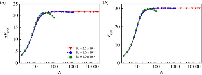
Plots  and
and  for a hairy surface of width
  as a function of the cylinder number N at the maximum load-carrying position. (Online version in colour.)
This optimized spacing between cylinders can be obtained by letting the derivatives of  and
and  with respect to
  be 0. These maximum values are denoted by
  and
and  , respectively.
 |
4.3 |
and
 |
4.4 |
Solutions to equations (4.3) and (4.4) give the critical values of  , or
, or  , which correspond to the optimized spacing of the inside cylinders. The detailed procedure to solve equations (4.3) and (4.4) can be found in appendix B. Then, the maximum values of
  and
and  can be calculated by substituting
  into equations (3.6) and (3.8), respectively. Note that the values of
  given by equations (4.3) and (4.4) are not necessarily the same but should be close with each other based the concept that both free energy and force analyses give consistent results. The range between those two values represents an optimized design by which both maximum load-carrying capacity and high mechanical stability can be obtained. We plot
  as a function of the Bond number for three different Young contact angles θY in figure 9. For all θY, both values of
  obtained by equations (4.3) and (4.4) are plotted. The region between these two lines can be a guide for designing hairy surfaces with both high load-carrying capacity and floating stability. It is surprising to find that the optimized spacing
  follows a simple power law with the Bond number with the fitted exponent equal to 1/3, that is,
| 4.5 |
The scaling law (4.5) is valid over an enormous range of Bond numbers and contact angles, because of the same mechanism, i.e. the compromise between the vertical capillary force and the gravity, as indicated by equation (4.2). The data points of the cone-shaped setae/hairs on the legs of water striders and on a cranefly wing and leg are also included in figure 9. Those data agree closely with our theoretical optimization prediction. Therefore, for the first time, we show that the setae on the legs of water striders are arranged in such an optimized way that those setae can give both high support and floating stability for water striders' legs. The spacing of the hairs on the wings of a fly is optimized so that water droplets will not be penetrated easily by those hairs during an impact and more importantly, will be repelled away easily owing to a reduced base contact area with the wing surface. Though the load-carrying capacity only decreases slightly when further decreasing the seta spacing, more densely packed setae will definitely cost more biological energy, and increase the adhesion and energy dissipation during the movement of water striders on water.
Figure 9.
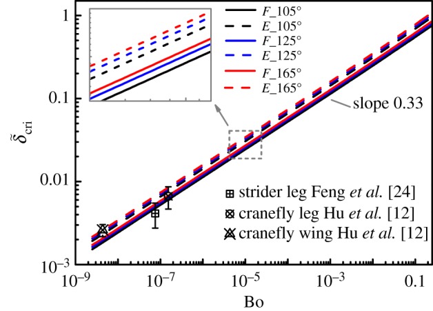
Dependence of  on Bo with respect to different Young contact angles: θY=10°, θY=125° and θY=165°. Solid lines denote
  which are obtained by the force analysis; dashed lines denote
  which are obtained by the free energy analysis. The data of the setae on water strider's legs are from Feng et al. [24] and the data of the hairs on a cranefly wing and leg are from Hu et al. [12]. The inset shows a magnified view of the plot in the region of the dashed box. (Online version in colour.)
(b). Influences of contact angle and Bond number
From §4a, we have learned that, for cylinders with a given Bond number Bo and contact angle θY, the optimized spacing of these cylinders can be obtained by equations (4.3) and (4.4). At the optimized cylinder spacing, i.e.  , the hairy surface exhibits the maximum load-carrying capacity per unit width, i.e.
  . In the following, we will investigate the influences of θY and Bo on
  and
and  at the optimized spacing, which are obtained by substituting
  into equations (3.6) and (3.8). Plots of
  and
and  as functions of θY are shown in figure 10. It is seen that, for very thin cylinders (e.g. Bo=2.5×10⁻⁷), both
  and
and  change very slightly with the increase of θY. The improvement of those maximum values owing to the increase of θY becomes more pronounced for thick cylinders (e.g. Bo=1.0×10⁻²). It is consistent with the previous results reported about a single cylinder floating on water [26,28]. Plots of
  and
and  as functions of Bo are shown in figure 11. For low hydrophobicity (e.g. θY=105°), the maximum values of
  and
and  first decrease slightly as the increase in the Bond number and decrease quickly when Bo is higher than 1.0×10⁻⁴. If the cylinders are superhydrophobic (e.g. θY=165°), then the maximum values of
  and
and  reach a maximum at Bo∼0.1. In other words, it is not necessary for hairy surfaces made of very thin cylinders (e.g. Bo<1.0×10⁻⁴) to be superhydrophobic. If the cylinders are thick (e.g. Bo>1.0×10⁻⁴), then superhydrophobicity can further increase the load-carrying capacity of hairy surfaces.
Figure 10.
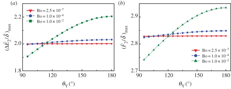
The maximum values of  and
and  as functions of θY with respect to different Bond numbers: Bo=2.5×10⁻⁷, Bo=1.0×10⁻⁴ and Bo=1.0×10⁻². (Online version in colour.)
Figure 11.
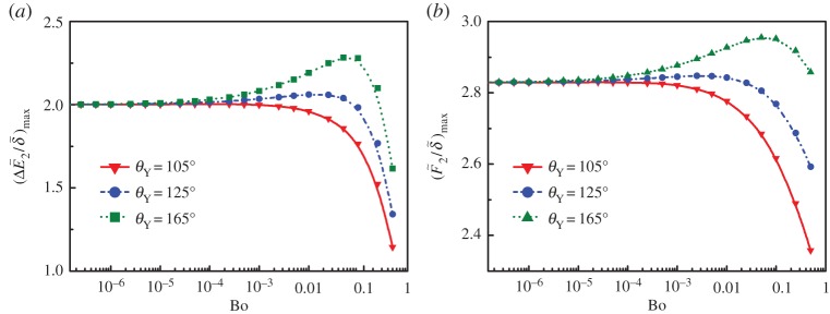
The maximum values of  and
and  as functions of the Bond number Bo with different Young contact angles: Bo=2.5×10⁻⁷, Bo=1.0×10⁻⁴ and Bo=1.0×10⁻². (Online version in colour.)
5. Concluding remarks
We have investigated the mechanism and optimization of hairy surfaces made from parallel cylinders floating on water to obtain the maximum load-carrying capacity and mechanical stability. It has been shown that the optimum design is achieved by adjusting the parameters, i.e. the spacing, the Bond number and the Young contact angle of the cylinders. For a hairy surface of a given width and Bond number, there exists an optimum cylinder spacing at which both high load-carrying capacity and strong floating stability can be obtained. The optimization arises from a compromise between the vertical capillary force given by the menisci and the gravity of the cylinders. The decrease in the cylinder spacing contributes to the increase in the vertical capillary force of the meniscus per unit width, but the increased gravity will reduce the increase in the total buoyant force. Moreover, for thin cylinders (e.g. Bo<1.0×10⁻⁴), surface hydrophobicity plays a negligible role in the increase of the load-carrying capacity. Otherwise, if Bo>1.0×10⁻⁴, then superhydrophobicity can be used to further improve the performance of hairy surfaces floating on water. We clarify that the setae/hairs on some insects' legs or wings follow the optimization principle we find here. Though the decrease in the buoyant force given by the inside meniscus per unit width is slight owing to the gravity for the setae, it is not necessary for them to grow more densely, or otherwise, it will cost more biological energy and may even harm the flexibility of the legs or wings.
In this work, the optimization design of a hairy surface is obtained and analysed at the position where the supporting force given by the outside menisci reaches a maximum. The choice of this position is based on the fact that the collapse of the outside meniscus generally leads to the failure of the whole cylinder raft. This does not exclude the possibility that locally wetting transition may happen as a result of, e.g. condensation [42], or an extremely strong impact and, then, induce the submersion of the whole surface. However, this is out of the range of the present topic. Note that we investigate a hairy surface model made from parallel cylinders and that both three-dimensional and hydrodynamic effects are neglected. The same optimization principle can also be applied to the design of rafts made from cylinders with arbitrary orientations and/or cross-sectional shapes, which requires a compromise of the vertical capillary force and the gravity per unit area. However, more integrated numerical methods are needed to characterize the pore structures and quantify the capillary and gravity forces generated by arbitrary cylinder geometries. This is because both the orientations and the cross-sectional shapes of the cylinders/fibres affect the capillary force [32,33]. Therefore, our theory can be a practical guide for designing micro-cylinder rafts with high load-carrying capacity.
The theory developed in this work can also be used for analysing the lifting process of hairy surfaces, which can be regarded as an antisymmetrical process to the sinking one with respect to the neutral position (figures 3 and 4). Thus, the optimization design of hairy surfaces for a maximum load-carrying capacity, on the other hand, increases the force and energy needed to lift a hairy surface from water. It is generally seen that though most insects' wings are superhydrophobic, it is not easy to lift the wing up once it is fully contacted with water surface. However, for insects living on water, low energy dissipation is needed for them to lift their legs from water so that they can quickly move and flee away from possible threats [10]. To meet such requirement, the setae on their legs need to be arranged in a special way, e.g. on a convex contour or circle (figure 1), rather than on a flat surface. During a lifting process, the convex contour enables the detaching of the contact menisci to happen gradually from both sides of a hairy surface instead of the simultaneous detachment of all the menisci, which will greatly reduce the force and energy needed to lift a hairy surface from water. From another point of view, those setae, together with sub-scale groove structures and wax surface, render water striders' legs superhydrophobic [24]. The superhydrophobicity decreases the adhesive force between the convex contour and water surface [27]. However, how the convex contour constructed by parallel cylinders influences the lifting process of the wetting contact lines needs further investigation.
Appendix A. Buoyant force
In appendix A, we give the detailed procedure to obtain equation (3.8) by a combination of equations (3.1)–(3.5) and (3.7). According to equations (3.1)–(3.5), differentiating the free energy changes with respect to θi (i=1,2) yields
 |
A1 |
 |
A2 |
 |
A3 |
 |
A4 |
and
 |
A5 |
According to equation (2.4), differentiating the displacement with respect to θi (i=1,2) yields
 |
A6 |
With  and equation (2.5), we have
 |
A7 |
and
 |
A8 |
By substituting equations (A1)–(A6) into equation (3.7) and combining equations (A6) and (A7), we get equation (3.8) after certain algebraic calculations.
Appendix B. Critical spacing
In appendix B, we give the detailed procedure to obtain  by solving equations (4.3) and (4.4). For a given Bond number Bo and Young contact angle θY, we calculate the optimized cylinder spacings for maximum buoyant force and free energy change per unit width at the maximum load-carrying position, respectively. We rewrite equation (2.5) as
 |
B1 |
At the maximum load-carrying position, θ1 and  are constant and only depends on the Bond number Bo and Young contact angle θY. Thus, by equation (2.4), we have
 |
B2 |
Substituting equation (B2) into equation (A7) yields
 |
B3 |
With equation (B3), differentiating equation (B1) with respect to θ2 yields
 |
B4 |
Equation (4.3) is rewritten as
 |
B5 |
where
 |
B6 |
 |
B7 |
and
 |
B8 |
By combining equations (B3)–(B8), we can get the critical cylinder spacing satisfying equation (4.3) after simple numerical calculation. Differentiating equation (3.8) with respect to θ2 yields
 |
B9 |
By substituting equations (B4) and (B9) into equation (4.4), we get the critical cylinder spacing satisfying equation (4.4) after a simple numerical calculation.
Funding statement
We acknowledge Major State Basic Research Development Program of China (grant no. 2011CB013101), National Natural Science Foundation of China (NSFC) under grant nos. 11225208, 10872003 and 11172001, The Alexander von Humboldt (AvH) foundation in Germany to support this work through project ‘Mechanics theory of materials with complex surfaces and its applications’ in the frame of the AvH program for funding a research group linkage.
References
- 1.Rothstein JP. 2010. Slip on superhydrophobic surfaces. Annu. Rev. Fluid Mech. 42, 89–109 (doi:10.1146/annurev-fluid-121108-145558) [Google Scholar]
- 2.Bhushan B, Jung YC, Koch K. 2009. Micro-, nano- and hierarchical structures for superhydrophobicity, self-cleaning and low adhesion. Phil. Trans. R. Soc. A 367, 1631–1672 (doi:10.1098/rsta.2009.0014) [DOI] [PubMed] [Google Scholar]
- 3.Liu X, Liang Y, Zhou F, Liu W. 2012. Extreme wettability and tunable adhesion: biomimicking beyond nature?. Soft Matter 8, 2070–2086 (doi:10.1039/c1sm07003g) [Google Scholar]
- 4.Feng L, et al. 2002. Super-hydrophobic surfaces: from natural to artificial. Adv. Mater. 14, 1857–1860 (doi:10.1002/adma.200290020) [Google Scholar]
- 5.Bhushan B. 2009. Biomimetics: lessons from nature—an overview. Phil. Trans. R. Soc. A 367, 1445–1486 (doi:10.1098/rsta.2009.0011) [DOI] [PubMed] [Google Scholar]
- 6.Yan YY, Gao N, Barthlott W. 2011. Mimicking natural superhydrophobic surfaces and grasping the wetting process: a review on recent progress in preparing superhydrophobic surfaces. Adv. Colloid Interface Sci. 169, 80–105 (doi:10.1016/j.cis.2011.08.005) [DOI] [PubMed] [Google Scholar]
- 7.Koch K, Barthlott W. 2009. Superhydrophobic and superhydrophilic plant surfaces: an inspiration for biomimetic materials. Phil. Trans. R. Soc. A 367, 1487–1509 (doi:10.1098/rsta.2009.0022) [DOI] [PubMed] [Google Scholar]
- 8.Neinhuis C, Barthlott W. 1997. Characterization and distribution of water-repellent, self-cleaning plant surfaces. Ann. Bot. 79, 667–677 (doi:10.1006/anbo.1997.0400) [Google Scholar]
- 9.Gao XF, Jiang L. 2004. Water-repellent legs of water striders. Nature 432, 36 (doi:10.1038/432036a) [DOI] [PubMed] [Google Scholar]
- 10.Hu DL, Chan B, Bush JWM. 2003. The hydrodynamics of water strider locomotion. Nature 424, 663–666 (doi:10.1038/nature01793) [DOI] [PubMed] [Google Scholar]
- 11.Wagner T, Neinhuis C, Barthlott W. 1996. Wettability and contaminability of insect wings as a function of their surface sculptures. Acta Zool. 77, 213–225 (doi:10.1111/j.1463-6395.1996.tb01265.x) [Google Scholar]
- 12.Hu HMS, Watson GS, Cribb BW, Watson JA. 2011. Non wetting wings and legs of the cranefly aided by fine structures of the cuticle. J. Exp. Biol. 214, 915–920 (doi:10.1242/jeb.051128) [DOI] [PubMed] [Google Scholar]
- 13.Thorpe WH, Crisp DJ. 1947. Studies on plastron respiration I. The biology of Aphelocheirus [Hemiptera, Aphelocheiridae (Naucoridae)] and the mechanism of plastron retention. J. Exp. Biol. 24, 227–269 [DOI] [PubMed] [Google Scholar]
- 14.Thorpe WH, Crisp DJ. 1949. Studies on plastron respiration IV. plastron respiration in the Coleoptera. J. Exp. Biol. 26, 219–260 [DOI] [PubMed] [Google Scholar]
- 15.Flynn MR, Bush JWM. 2008. Underwater breathing: the mechanics of plastron respiration. J. Fluid Mech. 608, 275–296 (doi:10.1017/S0022112008002048) [Google Scholar]
- 16.Marmur A, Ras RHA. 2011. The porous nano-fibers raft: analysis of load-carrying mechanism and capacity. Soft Matter 7, 7382–7385 (doi:10.1039/c1sm05156c) [Google Scholar]
- 17.Pan QM, Wang M. 2009. Miniature boats with striking loading capacity fabricated from superhydrophobic copper meshes. ACS Appl. Mater. Interfaces 1, 420–423 (doi:10.1021/am800116d) [DOI] [PubMed] [Google Scholar]
- 18.Jiang ZX, Geng L, Huang YD. 2010. Design and fabrication of hydrophobic copper mesh with striking loading capacity and pressure resistance. J. Phys. Chem. C 114, 9370–9378 (doi:10.1021/jp1009516) [Google Scholar]
- 19.Aussillous P, Quéré D. 2006. Properties of liquid marbles. Proc. R. Soc. A 462, 973–999 (doi:10.1098/rspa.2005.1581) [Google Scholar]
- 20.Jiang ZX, Geng L, Huang YD. 2010. Fabrication of superhydrophobic 3-D braided carbon fiber fabric boat. Mater. Lett. 64, 2441–2443 (doi:10.1016/j.matlet.2010.08.015) [Google Scholar]
- 21.Jin H, Kettunen M, Laiho A, Pynnönen H, Paltakari J, Marmur A, Ikkala O, Ras RHA. 2011. Superhydrophobic and superoleophobic nanocellulose aerogel membranes as bioinspired cargo carriers on water and oil. Langmuir 27, 1930–1934 (doi:10.1021/la103877r) [DOI] [PubMed] [Google Scholar]
- 22.Hsu SH, Woan K, Sigmund W. 2011. Biologically inspired hairy structures for superhydrophobicity. Mater. Sci. Eng. R 72, 189–201 (doi:10.1016/j.mser.2011.05.001) [Google Scholar]
- 23.Blow ML, Yeomans JM. 2010. Superhydrophobicity on hairy surfaces. Langmuir 26, 16071–16083 (doi:10.1021/la101847b) [DOI] [PubMed] [Google Scholar]
- 24.Feng XQ, Gao XF, Wu ZN, Jiang L, Zheng QS. 2007. Superior water repellency of water strider legs with hierarchical structures: experiments and analysis. Langmuir 23, 4892–4896 (doi:10.1021/la063039b) [DOI] [PubMed] [Google Scholar]
- 25.Vella D, Lee DG, Kim HY. 2006. The load supported by small floating objects. Langmuir 22, 5979–5981 (doi:10.1021/la060606m) [DOI] [PubMed] [Google Scholar]
- 26.Liu JL, Feng XQ, Wang GF. 2007. Buoyant force and sinking conditions of a hydrophobic thin rod floating on water. Phys. Rev. E 76, 066103 (doi:10.1103/PhysRevE.76.066103) [DOI] [PubMed] [Google Scholar]
- 27.Lee DG, Kim HY. 2009. The role of superhydrophobicity in the adhesion of a floating cylinder. J. Fluid Mech. 624, 23–32 (doi:10.1017/S002211200900593X) [Google Scholar]
- 28.Su YW, Ji BH, Zhang K, Gao HJ, Huang YG, Hwang K. 2010. Nature's design of hierarchical superhydrophobic surfaces of a water strider for low adhesion and low-energy dissipation. Langmuir 26, 18926–18937 (doi:10.1021/la103442b) [DOI] [PubMed] [Google Scholar]
- 29.Vella D. 2008. Floating objects with finite resistance to bending. Langmuir 24, 8701–8706 (doi:10.1021/la800245k) [DOI] [PubMed] [Google Scholar]
- 30.Zheng QS, Yu Y, Feng XQ. 2009. The role of adaptive-deformation of water strider leg in its walking on water. J. Adhes. Sci. Technol. 23, 493–501 (doi:10.1163/156856108X379155) [Google Scholar]
- 31.Ji XY, Wang JW, Feng XQ. 2012. Role of flexibility in the water repellency of water strider legs: theory and experiment. Phys. Rev. E 85, 021607 (doi:10.1103/PhysRevE.85.021607) [DOI] [PubMed] [Google Scholar]
- 32.Emami B, Tafreshi HV, Gad-el-Hak M, Tepper GC. 2012. Effect of fiber orientation on shape and stability of air–water interface on submerged superhydrophobic electrospun thin coatings. J. Appl. Phys. 111, 064325 (doi:10.1063/1.3697895) [Google Scholar]
- 33.Emami B, Tafreshi HV. 2012. Optimizing fiber cross-sectional shape for improving stability of air–water interface over superhydrophobic fibrous coatings. Appl. Phys. Lett. 100, 193104 (doi:10.1063/1.4711800) [Google Scholar]
- 34.Keller JB. 1998. Surface tension force on a partly submerged body. Phys. Fluids 10, 3009–3010 (doi:10.1063/1.869820) [Google Scholar]
- 35.Bhatnager R, Finn R. 2006. Equilibrium configurations of an infinite cylinder in an unbounded fluid. Phys. Fluids 18, 047103 (doi:10.1063/1.2185661) [Google Scholar]
- 36.Vella D, Metcalfe PD, Whittaker RJ. 2006. Equilibrium conditions for the floating of multiple interfacial objects. J. Fluid Mech. 549, 215–224 (doi:10.1017/S0022112005008013) [Google Scholar]
- 37.Wei PJ, Shen YX, Lin JF. 2009. Characteristics of water strider legs in hydrodynamic situations. Langmuir 25, 7006–7009 (doi:10.1021/la900185a) [DOI] [PubMed] [Google Scholar]
- 38.Rapacchietta AV, Neumann AW, Omenyi SN. 1977. Force and free-energy analyses of small particles at fluid interfaces. I. cylinders. J. Colloid Interface Sci. 59, 541–554 (doi:10.1016/0021-9797(77)90050-9) [Google Scholar]
- 39.Marmur A. 2003. Wetting on hydrophobic rough surfaces: to be heterogeneous or not to be?. Langmuir 19, 8343–8348 (doi:10.1021/la0344682) [Google Scholar]
- 40.Patankar NA. 2004. Transition between superhydrophobic states on rough surfaces. Langmuir 20, 7097–7102 (doi:10.1021/la049329e) [DOI] [PubMed] [Google Scholar]
- 41.Xue YH, Chu SG, Lv PY, Duan HL. 2012. Importance of hierarchical structures in wetting stability on submersed superhydrophobic surfaces. Langmuir 28, 9440–9450 (doi:10.1021/la300331e) [DOI] [PubMed] [Google Scholar]
- 42.Wier KA, McCarthy TJ. 2006. Condensation on ultrahydrophobic surfaces and its effect on droplet mobility: ultrahydrophobic surfaces are not always water repellant. Langmuir 22, 2433–2436 (doi:10.1021/la0525877) [DOI] [PubMed] [Google Scholar]


