

Abstract
In this paper, a novel cell stretcher design that mimics the real-time stretch of the heart wall is introduced. By culturing cells under stretched conditions that mimics the mechanical aspects of the native cardiac environment, better understanding on the role of biomechanical signaling on cell development can be achieved. The device utilizes a moving magnet linear actuator controlled through pulse-width modulated power combined with an automated closed loop feedback system for accurate generation of a designated mechanical stretch profile. The system’s capability to stretch a cell culture membrane and accuracy of the designated frequency and waveform production for cyclic stretching were evaluated. Temperature and degradation assessments as well as a scalable design demonstrated the system’s cell culture application for long term, in vitro studies.
Keywords: Cell stretcher, Moving magnet linear actuator, Pulse-width modulation, Feedback controller system, Mechanical stimulation
INTRODUCTION
It is well documented that cellular development is influenced by the surrounding in vivo mechanical environment.8,15,17 In particular, cardiac development is sensitive to alterations in biomechanical and biophysical signals. For example, athletic exercise can lead to physiological cardiac hypertrophy which is the lengthening and thickening of contractile cells in the heart wall. This type of hypertrophy increases the filling capacity of the left ventricle and improves heart function.2 Abnormal biomechanical or biophysical factors are also hypothesized to be related to shifts in cellular phenotype leading to pathological tissue development. Support for this hypothesis stems from observations of abnormal amplitude and frequency patterns in cases of congenital and degenerative heart diseases such as left heart hypoplasia18 and pathological hypertrophy.6
In the past few decades, mechanical stimulation devices and bioreactors have been used to understand the developmental and regenerative process of cells. While these devices share a similar goal of trying to mimic the in vivo milieu,14 the biomechanical environment is complex and there are many forms of physical stimulus including tension, shear, hydrostatic pressure, and compression.10 We are most interested in tension forces, specifically in-plane distension, which is an indirect, uniform stimulus and more easily controlled. 3 Vacuum pressure systems are a commonly used class of in-plane distention cell stretcher.1,7 Currently, a commercial product called the Flexercell® FX-4000™ Tension Plus System (Flexcell Corporation, McKeesport, Pennsylvania, USA) uses a vacuum system to stretch cells cultured on the silicone membrane of BioFlex® Culture Plates (Flexcell). However, studies of this system have indicated limitations in its accuracy of stretching the membrane based on arbitrary waveforms at frequencies matching the regularly stretched myocardium.5 Another common method for stretching cells is using a motor driver mechanism. Motors are cheap, can provide a lot of force, and are easily controlled through the voltage. One design is a cam-shaft configuration which pushes a cell culture membrane surface in an oscillatory manner based on an off-centered, rotating shaft. While a cam-shaft is robust and can generate great force at high speeds, the wave shapes are dependent on the shaft geometry and are unable to change during the operation of the cell stretcher.9
The goal of this project was to develop a cell stretcher that stimulates cardiac cells in a more physiologically relevant manner to mimic the stretch of the myocardial wall. For this goal, we sought to create a device with the following parameters: (1) Capability to stretch a membrane up to 5–15% stretch, (2) Regularly stretch a membrane up to frequencies of 4 Hz, (3) Alter stretch profile on a cycle-to-cycle basis based on arbitrary waveforms with high fidelity and (4) Create a design that is suitable for routine cell culture use including assessing temperature stability at 37 °C, scalability and long-term degradation. Our resulting device dubbed the arbitrary waveform membrane stretcher (AWMS) cell stretcher system meets these parameters by utilizing a moving magnet linear actuator (MMLA) powered by pulse-width modulation (PWM) and controlled with an automatic feedback controller system.
MATERIALS AND METHODS
AWMS Overview
The AWMS is comprised of three major mechanical components: a coil, a lever, and the plungers (Figs. 1a, 1b). The coil is a MMLA which converts electrical energy into linear mechanical force. When current is applied to the coil, a magnetic field is generated that repels a moveable magnetic core and armature. The downward force is transmitted and amplified through a lever to a set of plungers at the opposite end (Fig. 1c). These plungers push against a cell culture membrane and variations to the transmitted upward force produce dynamically stretched culture environments.
FIGURE 1.

(a) Images of the 3D CAD model (Solid works, Waltham, MA) of the AWMS, (b) the resulting device created through the Tufts Department of Biomedical Engineering machine shop and self-fabricated parts and (c) motion diagram of cell stretcher system (d) diagram of plunger assembly with plunger rods threaded through plunger base plate.
MMLA and Pulse Width Modulation Theory
The driving mechanism chosen is a MMLA which is essentially the inverse of a loudspeaker. Instead of a fixed permanent magnet with a voice coil that moves as a result of an electric current, an MMLA uses a fixed coil and a freely moving permanent magnet. Anytime current passes through a wire, a magnetic field is generated. A current flowing through a coil of wire with many turns forms a strong electromagnetic field. These coils can be modeled after solenoids where the simplified formula for the magnetic field strength is:
| (1) |
where μ0 is the magnetic constant, N is the number of turns, I is the current, and l is the length of the coil. To translate the magnetic force into mechanical force, a neodymium magnet is placed inside the coil oriented with an opposite polarity. The opposing magnetic fields cause the magnet and coil to repel each other and create a physical displacement.
MMLAs can rapidly switch directions and generate high frequency waveforms.4 While this system could be controlled to produce a wider range of desired waveforms than a cam motor system, the coil/magnet system requires significant amounts of current to generate the necessary force to stretch the Flexcell® membrane. At high currents, the resistance in the wire generates heat in the coil, which can demagnetize the neodymium magnets. Therefore, we examined methods of increasing the magnetic force without requiring excessive current. From Eq. (1), one could change the magnetic constant by using a stronger magnet, increase the number of turns in the coil, decrease the length of the coil by adding more layers, or decrease the resistance of the coil using thicker wire.
To control the displacement of the magnet inside the coil, the average power was regulated using pulse width modulation (PWM). The main principle of PWM is that average power delivered to a load is dependent on the pulse width and duration of the pulse train. In theory, a power supply outputting a regulated 5 V would provide 50% of the maximum average power to the coil if the duty cycle of the pulse train was 50%. By programming a series of pulse trains of varying duty cycle, the magnet displacement can follow any arbitrary waveform.
Design of the Cell Stretcher
While MMLAs can produce high frequency oscillations, they generally cannot provide significant force. Therefore, one of our main design objectives was to optimize the different parts of the cell stretcher to maximize the force delivered by the system. A MMLA converts electrical energy into mechanical force by creating an electromagnetic force through a coil of magnet wire. In theory, the number of turns of wire is proportional to the strength of the magnetic field strength of the coil when current flows through. However, in reality, wire takes up volume which means that the wire on the outer layers of the coil have less influence compared to the inner coil wire on the neodymium magnets at the core. Metal wires also have some resistance such that a single thick wire wrapped hundreds of times could have several ohms of resistance. Overheating is a concern because high temperatures are neither safe for cells nor neodymium magnets which have a maximum operating temperature of 80 °C.16 To maximize the mechanical force generated from our MMLA, we explored different combination of wire thickness, the number of turns, and length of coil. We also explored reduction of the overall coil resistance by dividing the single wire coil into multiple wires joined in a parallel resistance network.
The lever system, which translates the vertical motion of the MMLA to the plungers, was designed to amplify the mechanical force through mechanical advantage. By adjusting the fulcrum position, we increased the force to the plungers in a 3:1 ratio. Although the movement of the lever is radial and not linear, we determined that the displacement necessary to stretch the cell culture membrane was small enough to approximate the movement of the coil armature and plungers as linear.
The plungers consist of Delrin® (Acetal Homopolymer) caps that rest on metal rods which are fixed to a base plate. Since the Delrin® caps interface with the cell culture membrane; we chose this thermoplastic because it is easily machinable and has a low coefficient of friction. We experimented with several designs for the cap surface such as dome shaped, conical, and flat. While the flat surface has the greatest potential for the cell culture membrane to catch on the edges, it also provides a uniform surface area of stretch which we can easily measure. To further reduce the friction, we added a small cylindrical rim which lowers the surface area of the Delrin® in contact with the membrane. The plunger rods are threaded into a base plate (Fig. 1d) which serves multiple functions. The device can be configured to stretch all wells of a six-well plate or fewer wells by removing rods from the base plate. The height of each rod can also be customized in order to selectively stretch certain wells more or less than the others.
Design of the Controller System
A LabVIEW (National Instruments, Austin, TX) controller system was created to generate designated mechanical environments by automatically adjusting the power to the MMLA in a closed feedback loop based on measured plunger displacement. Real-time displacement of the plungers was measured with a linear variable differential transformer (LVDT) and displacement was related to the percent stretch of the membrane via imaging studies (see Fig. 4). A signal conditioner with a low pass filter was built to reduce noise in the output of the LVDT and allow adjustments of gain and offset before the signal was captured by an NI-USB 6221 BNC data acquisition (DAQ) instrument. Pulse trains were generated for PWM by the counter outputs of National Instruments (NI) Compact DAQ 1-Slot USB Chassis (National Instruments) (Fig. 2).
FIGURE 4.

(a) Extracted image from video recording of marked membrane. For calculation of percent stretch of the wells, red dots were drawn and the background behind the plunger was colored green to isolate the dots and plunger cap by setting a specific threshold. Distance from the center in millimeters is indicated by the yellow numbers and an example area of interest is designated by the blue square for the outer 10 mm region. (b–e) Plots of the calculated percent stretch vs. plunger displacement at varying distances from the center of the plunger for four viewable wells on a single device. (f) Average overall change in percent stretch to LVDT reading for these four wells with standard deviation. Blue boxed value indicates rate of percent stretch to mm increase for these four wells with standard deviation. Black boxed value indicates rate of percent stretch to mm increase determined from four individual devices with standard deviation. (g) Plot of the percent stretch vs. duty cycle for three, four, and six wells being stretched. Blue represents three wells stretched, red presents four wells stretched, and green represents six wells stretched. Percent stretch was calculated based on the displacement of the LVDT. All devices were stretched at a constant 5 V power supply while the duty cycle was pulse width modulated through a MOSFET driver.
FIGURE 2.
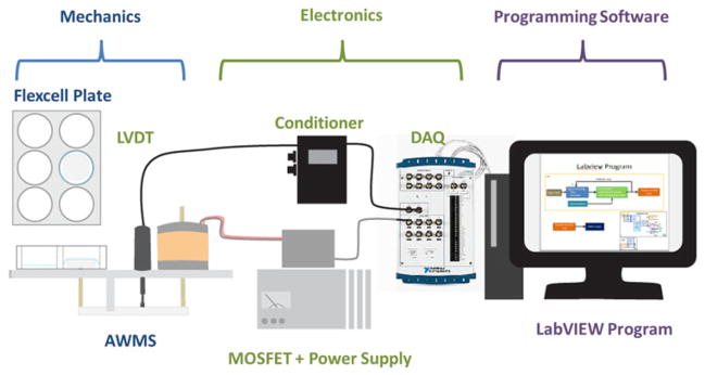
Feedback system flow diagram.
LABVIEW was selected as a programming language to interface with the DAQs and for its customization capability. The user interface contains parameter designations for maximum percent stretch, frequency and waveform to regularly stretch the membrane. Additionally, variable amplitude and frequency output using a Gaussian or random distribution based on a set distribution size can be selected (Fig. 3). Calibration is completed once average point-by- point error is below a user-designated acceptable error and the controller switches to output the designated waveform until routine re-calibration is instituted after a specified number of cycles.
FIGURE 3.

(a) Image of the overall user interface and (b) zoomed-in display of the input panel for setting up an experiment. Input panel is divided into calibration, waveform parameters and variable output sections. User can input an arbitrary waveform, amplitude, frequency and variable output based on a designated distribution.
Power is automatically adjusted per cycle by a proportional-integral-derivative (PID) closed feedback loop based on the calculated point-by-point error between the LVDT measured output and the ideal waveform. PID controllers are feedback loop mechanisms represented by the mathematical equation:
| (2) |
where e(t) is the error calculated by the difference from the ideal to the actual signal over time, Kpe(t), consists of multiplying the error value by a proportion and adding that value to the output, Ki ∫ e(t)dt, computes the integral or sum of the error which accelerates adjustment and helps eliminate the steady-state error from a pure proportional controller, , computes the derivative in error over time which slows changes in the controller output.
VALIDATION OF CRITICAL DESIGN PARAMETERS AND SYSTEM PERFORMANCE
The device’s capability to stretch the membrane was evaluated by determining the percent change in the membrane’s surface area in stretched vs. static conditions. Percent stretch was calculated with the following equation:
| (3) |
Deformation of the membrane was determined by video imaging analysis with set-ups consisting of 3, 4 and 6 plungers to equally distribute force. To mark off areas of interest, dots were drawn equidistant from the center of the plunger-membrane interface at 2.5 mm increments up to 10 mm (Fig. 4a). Video imaging was taken from directly above the membrane while the power delivered to the solenoid was increased in a stepwise fashion by 10% duty cycle increments. Images from each static condition were extracted and analyzed by ImageJ (NIH, Bethesda, MD) to calculate the percent stretch and assess for variability over the membrane and amongst devices. Displacement towards the camera was corrected by normalizing to the area of the plunger cap. The system’s capability to accurately stretch the culture membrane based on an arbitrary waveform was evaluated by determining the lowest achievable average error and the time required to reach this status. To test the system’s capabilities in producing complex arbitrary waveforms, a waveform modeling the left ventricular volumetric loading wave was used which has physiological relevance to cardiac development and may stimulate differentiation. The peak stretch was 5% which has been commonly used in other mechanical stimulation experiments.11,13 The device’s capability to create the waveform from a starting zero output and with optimized parameters was tested. The PID coefficients were set to 0.1 for slow gradual adjustment and scale factor was set to 10% for initial minimum output. Optimized parameters were determined by qualitative observations for improved accuracy and speed at 0.2, 0.1 and 0.5 for the respective PID components and a scale factor of 45%. Waveforms generated at 1, 2, 3 and 4 Hz were evaluated. Testing was automated by a program routine that continued PID calibration until 30 cycles had passed since a reduced average error had been achieved. 10 rounds of this program routine were run for each frequency and the results were averaged.
Consistency of membrane stretch based on a designated waveform was also evaluated by determining the average waveform generated, average overall error and average error per point. A 5% stretch left ventricular waveform at frequencies from 1 to 4 Hz was generated with the optimized calibration parameters and lowest average error determined previously. Recordings for 500 waveforms were taken for analysis. The device’s capability to function with minimal time delay between cycles was also demonstrated by observing the frequency distribution of the output at 1, 2, 3 and 4 Hz. LVDT readings were recorded for a 5% stretched left ventricular waveform. 150,000 cycles of the recorded waveforms were processed by a fast Fourier Transform (FFT) with MATLAB’s built-in FFT functions (Fig. 5).
FIGURE 5.
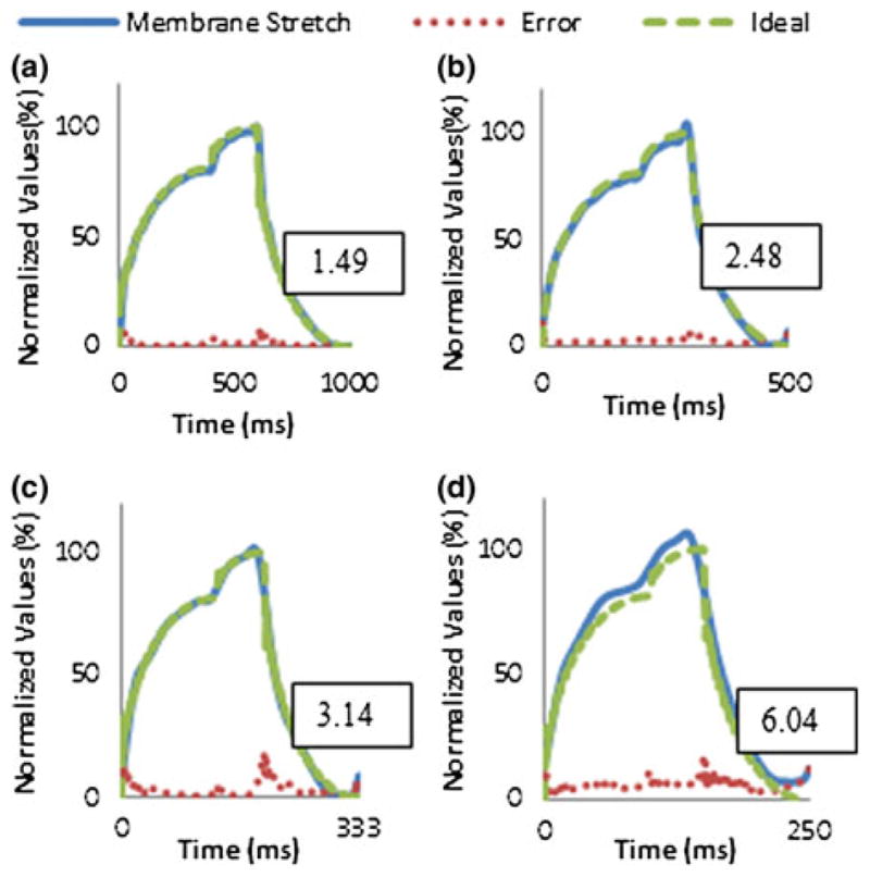
The solid line represents averaged membrane stretch per cycle from 500 cycles and normalized to 5% stretch for (a) 1 Hz, (b) 2 Hz, (c) 3 Hz and (d) 4 Hz. The dashed line represents the ideal waveform normalized to 5% stretch. The dotted line represents average error per point and boxed values represent average overall error.
Cell Culture Incubator Use
The in vitro cell culture often consists of highly regulated incubators which can be hostile to mechanical and electrical components. The system was designed to meet spatial, temperature, and durability limitations along with ease of sterilization for routine use in cell culture environments. All non-electronic components were designed to be disassembled and sterilized, with materials chosen to be able to withstand the high pressure and temperature steam treatment in an autoclave. Electronic components such as the wiring and magnet could be sterilized using less corrosive methods like isopropyl alcohol and UV light. Due to resistance of the magnet wire, the coils generate heat when current flows through them. Although the resistance (and hence heat) can be reduced by increasing the thickness of the wire, using parallel wiring, and using pulse width modulation, we were concerned about the heat affecting the neodymium magnet and the Flexcell® plate temperature. To assess the effect of coil heating on the reliability of the system, three different temperatures were recorded while four AWMS devices, each with six posts, were programmed to stretch in the incubator. All four devices were programmed with a 1 Hz, 5% stretch, and left ventricle volume waveform. One digital thermometer was taped to the outside of the coil and another was taped to the surface of the Flexcell® plate. The final temperature reading was taken from the incubators thermometers which are located near the top inside. The devices were operated for 4 h and temperatures were recorded initially and at the end. Long-term use and degradation was measured by observing the changes in the stretch performance and physical conditions of materials after multiple weeks of operation. Degradation of the mechanical and electronic parts was qualitatively measured by disassembling the devices and recording the condition of stressed areas and areas of mineral buildup or corrosion.
Cell Study
To determine whether cells maintained adherence to the Bioflex plate and to observe changes in morphology, neonatal cardiac cell populations were cultured and fixed by immersing them in 4% paraformaldehyde. The center region of the membranes were excised with a scalpel and stained for cardiac specific α-actin (Santa Cruz Biotechnology, Dallas, Texas) with Alexa Fluor® 555 (Life Technologies, Carlsbad, CA) at 1:250 primary and 1:500 secondary and Hoechst DAPI stain (Sigma-Aldrich, St. Louis, Missouri) at 1:1000 dilution. Images were taken with an Olympus IX81 microscope.
To demonstrate the device’s potential to influence cell development, fetal cardiac cell populations were mechanically stimulated and shifts in RNA expression of contractile proteins were quantified. Fetal cardiomyocytes were isolated from a nitrofen-induced congenital heart defect (CHD) model by dosing a pregnant Sprague-Dawley® rats at 10 days gestation under short isoflurane anesthesia with 100 mg of nitrofen (WAKO Chemical, Osaka, Japan) dissolved in olive oil by a gastric tube. As a control, normal rats were given a dose of olive oil without nitrofen. Cesarean section was performed 21 days gestation.
Fetal and neonatal cardiac cells were isolated as previously described.19 All animal procedures were in accordance with Institutional Animal Care and Use Committee protocols at Tufts University and were approved by the US Animal Welfare Act. Isolated cardiac cells were seeded at ~1.0 million cells/well on pre-coated Collagen I BioFlex Culture Plates® with an additional coating of 4 μg/cm2 Human Plasma Fibronectin Purified Protein (Millipore, Billerica MA) and cultured for 4 days under static conditions to ensure adherence. Afterward, cells were mechanically stimulated for 2 days under a left ventricular volume loading waveform at 1 Hz and 5% stretch with a 10% Gaussian frequency distribution to assess the effects of controlled variability on stimulated culture. The underside of the flexible membrane was coated with silicone lubricant (Loctite, Düsseldorf, Germany) to minimize friction between the plunger and the membrane. Cell cultures were fed culture medium containing 10% horse serum (Sigma-Aldrich), 2% fetal bovine serum and 1% Penicillin Streptomycin solution in Dulbecco’s Modified Eagle Medium (DMEM) (Gibco, Grand Island, NY). Medium was changed every 2 days. As a control, a second plate was cultured under static conditions for the same time duration. RNA isolation and quantitative real-time polymerase chain reaction (qRT-PCR) were performed utilizing TaqMan® (Applied Biosystems, Foster City, CA) probes as described.12 Expression of myosin heavy chain α and β (MYH-α & β) were measured and normalized to GAPDH expression. Statistical significance was determined with a student’s t test and significance was assigned for p values less than 0.05.
RESULTS
Device Performance Analysis
Video analysis of four membranes from a single device determined that membrane stretch was relatively uniform in each well over the plunger-membrane interface with a linear relationship between the plunger movement and the percent stretch (Figs. 4b, 4e). Average overall stretch was reproducible in each individual well, however, some deviations in generated stretch was observed amongst wells. Similar results were observed in three other devices and results were averaged giving a 3.66% stretch/mm relationship with a standard deviation of 0.401 (Fig. 4f). Set-ups of 3, 4 and 6 stretched wells were tested with plunger set-ups that equally distributed force from the MMLA achieving percent stretches at or greater than 15% with fewer caps (Fig. 4g).
Generation of the arbitrary waveform from a starting zero output achieved average errors below 5% for each frequency setting with calibration requiring over a minute. Optimized parameters generally achieved lower average errors and were reached in under a minute (Table 1). Average overall error for 500 cycles was determined to remain below 5% for 1– 3 Hz and drift past 5% for 4 Hz. Average error per point was observed to be higher at step-like rises and drops in the waveform especially at 4 Hz. Additionally at 3 and 4 Hz, the device had greater difficulty returning to a zero value for each cycle (Fig. 5). For assessing accurate frequency of output, 150 k waveforms were recorded and analyzed by a FFT function in MATLAB giving a high relative peak with distributions around 0.1–0.2% was observed for each frequency setting (Fig. 6). Frequencies at the distribution peak for 1, 2 and 4 Hz matched designated settings. Peak of the 3 Hz frequency distribution was shifted by around 0.015 due to limitations with LabVIEW’s microsecond resolution that forced rounding of waveform parameters.
TABLE 1.
Lowest average achievable error and corresponding average time of calibration for 1, 2, 3, and 4 Hz from 10 individual runs each.
| Frequency (Hz) | Lowest average achievable error (%) | Average time required (s) |
|---|---|---|
| From scratch | ||
| 1 | 1.19 ± 0.12 | 96.50 ± 11.92 |
| 2 | 1.72 ± 0.03 | 84.00 ± 8.32 |
| 3 | 3.06 ± 0.51 | 74.7 ± 6.00 |
| 4 | 2.94 ± 0.13 | 70.20 ± 8.59 |
| Adjusted parameters | ||
| 1 | 1.08 ± 0.37 | 47.40 ± 4.68 |
| 2 | 1.42 ± 0.55 | 42.90 ± 10.58 |
| 3 | 2.38 ± 0.25 | 37.70 ± 6.98 |
| 4 | 2.74 ± 0.21 | 26.10 ± 11.96 |
FIGURE 6.
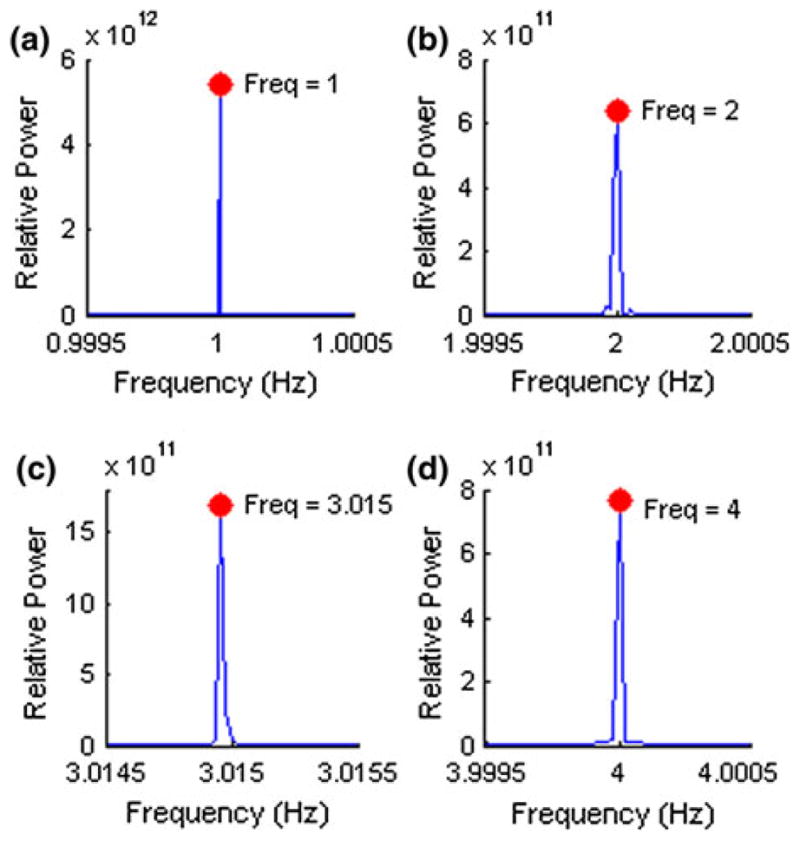
Periodogram of device output from 150 k waveforms running at (a) 1 Hz, (b) 2 Hz, (c) 3 Hz and (d) 4 Hz. Value of distribution peak is marked by a dot and the corresponding frequency is labeled.
Cell Incubator Use
Modifications to the lever length, plate walls, and legs were made to allow three devices to fit side-by-side with a fourth device in the back of a standard 17 in. × 17 in. incubator shelf (See Fig. 7). The final dimension of the device base plate was 11 in. long and 5 in. wide. The legs were dimensioned to be 3 in. tall to give users space above the devices to maintain the wiring and cell culture plates. For mechanical components, the parts constantly in motion such as the magnet/coil, lever assembly, and plungers were inspected for signs of friction and wear. For electronics, wire connections and the MOSFET box were inspected for corrosion or buildup of oxidized substances due to galvanic effect. After 4 weeks of continuous use in an incubator, we observed metal dust shavings most heavily in the lever assembly and lining the inside of the coil form. This suggests an eventual need to replace these components. Some wires and connectors also showed signs of rust after sitting in the incubator for 2 weeks. Although the degradation of these components was minor, corrosion especially to wiring can cause device failure and potentially damage other components. Temperatures were measured before and after a 4-h operation (Table 2). Temperatures at the end of the 4-h had equilibrated and were stable. The coil temperature increased from incubator temperature to 63.3 °C. The incubator and cell culture plate temperature had a change of less than 0.2 °C.
FIGURE 7.
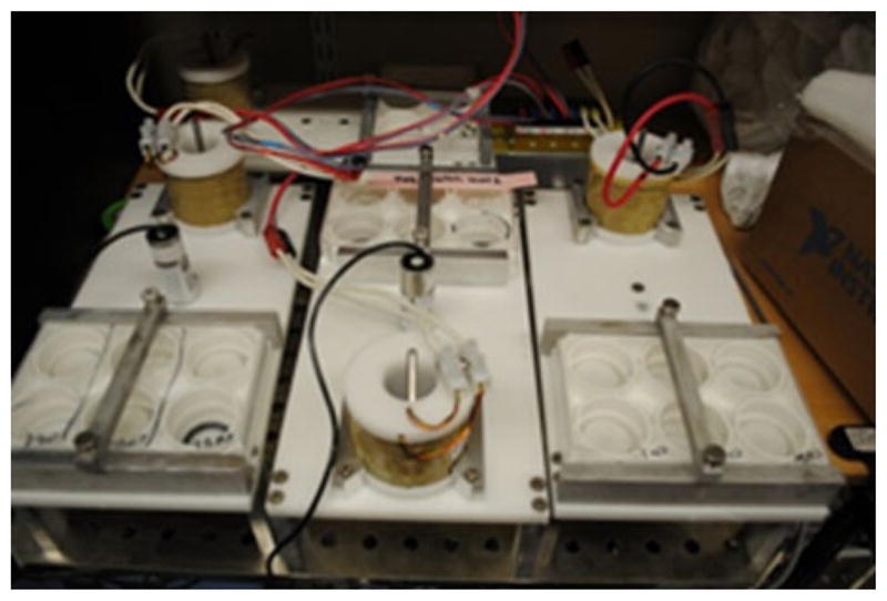
Layout of AWMS devices on an incubator shelf. Four devices are arranged onto one incubator shelf with three devices in the front and one in the back left. The back right corner is the MOSFET box which drives the MMLA for each device.
TABLE 2.
Temperature readings to determine effect of coil heating on system.
| Source | Initial temperature (°C) | Final temperature (after 4 h) (°C) |
|---|---|---|
| Incubator reading | 37.0 | 36.8 |
| Cover plate | 35.6 | 35.5 |
| Coil | 38.0 | 63.3 |
Changes to cell adherence and morphology for cardiomyocyte populations were assessed before and after mechanical stimulation was applied (Fig. 8a). During the designated period of study, cells consistently maintained adherence to the coated silicone membrane and demonstrated visible contractions during static and stretched culture. Cell density varied based on the location in the membrane with the highest density in the center. Greater stretch, frequency and longer terms of cell culture provided inconsistent results due to detachment of cell monolayer from the membrane surface.
FIGURE 8.
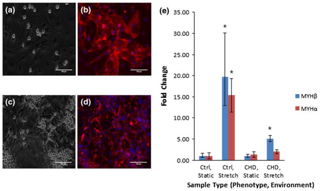
Transmitted and overlayed fluorescent images for neonatal cultured samples (a–b) before and (c–d) after stretch stained for cardiac specific α-actin and nuclear stain. α-actin staining is displayed in red and nuclei staining are displayed in blue. Images were provided with a 100 μm scale bar. (b) Fold changes in MYH-α & β from samples cultured 4 days statically and 2 days stretched before RNA isolation. Four replicates from each group are represented in the graph. Fold change was normalized to healthy cell population cultured statically over the period of study. Sample types are labeled by healthy or disease cell populations and static or stretched culture.
To demonstrate the device’s capability for cell culture studies, isolated cardiac cell populations were mechanically stimulated and influence on cell development was quantified. In each group, four individually cultured replicates were analyzed. Gene expression of MYH-α and β was selected for their importance in proper contractile function and development in cardiomyocytes. Based on the results, there was significant increased expression of MYH-β expression for both stretched health and diseased cell population and for MYH-α of the control cell populations compared to the static control sample, showing an effect of stretch (Fig. 8b).
DISCUSSION
Conceptual Design
The goal behind creating a device that reproduces the real-time stretch of the in vivo myocardial wall in vitro is to isolate the role of the mechanical environment in healthy and diseased cellular development. Our long term goal is to apply our improved understanding of how extracellular signals from the mechanical environment can influence proper myocardial development to the creation of novel biotechnologies and regenerative medicines to treat cardiac diseases. Our study began with the hypothesis that the fast activation and response of a MMLA powered by PWM could produce arbitrary waveforms at frequencies up to 4 Hz. Initial tests demonstrated the capability to produce rectangle, triangle and sine waveforms; thus we shifted our focus to producing more complex and physiologically relevant waveforms present in the myocardial environment. Since proper function and development of the left ventricle is critical for systemic circulation, we selected the left ventricular loading volume waveform as both a complex and relevant waveform for cardiac studies. However adjusting the output to compensate for shifts in membrane compliance and MMLA characteristics under long term usage to match a desired waveform is difficult to do manually. Thus we added a closed loop feedback system to our set-up to autonomously generate our designated output.
Two main advantages of the feedback system are (1) a simple solution to generate desired waveforms and (2) the ability to adjust for variations of stiffness or long-term compliance of the membrane. Without a feedback system, the MMLA can produce various waveforms; however, replicating a desired waveform was very difficult. For example, to prevent the plunger from overshooting a quick rise time, a user would have to lower the peak time points and use trial-and-error until the waveform was the correct amplitude. Since each waveform can be composed of hundreds of points, the task of manually adjusting a custom waveform was infeasible. The feedback system increases the power of the arbitrary waveform by automating the adjustments and using PID to generate the desired waveform through minimal iterations.
The automated controller system also allowed for expansion of the device’s capabilities by allowing for routine programming capabilities and generation of variable amplitude and frequency output based on a designated distribution. The device’s capability to automatically re-calibrate and change output parameters based on a programmed routine were demonstrated by the validation tests themselves with automation of both repeated trials and changes in parameters. This allows for the possibility of controlled variable output by taking additional calibration steps with the designated distribution along with automated interpolation and selection of waveform parameters.
Device Performance
The AWMS’s capabilities to create a regularly stretched dynamic mechanical environment based on our designated parameters was confirmed when certain device configurations were utilized. Based on observation of the percent stretch of the membrane surface, we determined a relatively uniform and linear relationship between the percent stretch and the plunger displacement. However, our analysis was limited to the flat plunger-membrane interface within 10 mm from the center since areas outside of this range were stretched off the edge of the plunger interface and thus were imaged at an angle. Therefore, cell studies were purposely limited to these areas by selectively cutting out and collecting cells from this region. Considering that the current devices are custom-built, differences in device outputs were expected, thus adjustable components such as the plunger heights were designed to be individually set and were calibrated so that vertical movement of the plungers could be similar amongst wells to reduce variability. Thus, improved manufacturing and methods of calibration are expected to further reduce variability in future models of this device.
Evaluation of the output demonstrated an accurate production of the designated frequency up to 4 Hz with distribution of 0.1–0.2%. Additionally, accuracy of the waveforms produced from 10 individual runs each at these frequencies was demonstrated by achievable average overall errors below 5% with generally slight drifts in consistency over time. Although more drifts in accuracy were observed for higher frequencies, routine programming possibilities with our controller system allows for re-calibration of the output after a set number of cycles. Additionally, limitations to accurately producing some frequencies were observed and could be overcome by additional LabVIEW software allowing for commands at a microsecond resolution. However, this limitation was not considered significant and not corrected since the deviation was below 1% and output maintained a tight distribution.
Ideally, the AWMS could also stretch all six wells of a Flexcell® plate beyond 15% stretch, which would be comparable to other mechanical stretchers. However, limited stretch force and heating issues are potentially damaging to both the device due to fractional demagnetization of the neodymium magnet at temperatures past 80 °C and cells cultured in the heated incubator environment when device output is forced to its limits. The stretch test did show that the AWMS is fully capable of stretching six wells at 5% and by using fewer wells, higher stretches can safely be used. Furthermore, improvements to the driving mechanism such as optimization the output vs. heating of the coil and different or multiple neodymium magnet configurations could be utilized to increase the potential output of the device.
Cell Culture Incubator Use
As part of the criteria for designing a cell stretcher for cell culture application, we designed a system to control multiple devices. Using a standard sized incubator, we determined that four devices could fit comfortably on one shelf and in total eight devices could fit in one incubator with sufficient room to access cell culture plates. The AWMS system has an advantage over pneumatic and vacuum driven systems because the electrically driven devices allows for relatively simple scalability and arrangement. With an air or liquid based driving mechanism, multiple devices require addition pumps or complex tubing to equally distribute the pressures.
The incubator is a hostile environment for mechanical and electronic components. The temperature is maintained at 37 °C and the air is always humid which increases the rate of corrosion. In addition, the AWMS coils produce heat which may affect cell culture since incubators are not usually designed with cooling units. Heating assessments determined the coil can get hot but not above maximum operating temperature of 80 °C. However, overheating is a concern and one study showed that devices programmed to run 5% stretch at 1 Hz for 4 h had coil temperatures reach 63.3 °C. Increased stretch percentages or misuse of the device could push the heating to unsafe temperatures. One method we implemented to prevent overheating is to raise the initial position of the magnet to start more inside the coil. This shifts the maximum force from the coil to a support higher percent stretches. While this can extend the max force, it is only a minor fix and alternative methods of reducing heat or increasing force are needed. The effect of the coil heating on the ambient incubator temperature determined that the incubator can dissipate the heat such that the plate temperature is not affected. This is significant because the coil and plate are about 15 cm away and the incubator is able to keep the temperature of the plate from increasing. In fact, the temperature dropped slightly but less than 0.2 °C. This drop may be due to opening and closing of the of the incubator door when cell culture samples were moved. Natural fluctuation of the temperature is also expected since the incubator is constantly adjusting to maintain a constant temperature.
Long-term reliability was assessed by observing the mechanical and electrical degradation after use. After several weeks of constant operation, we observed only minor wear and warping. In particular, wire connections and threaded components had a thin layer of mineral buildup and corrosion due to the humidity in the incubator and isopropyl sterilization. One solution is to apply a protective coating such as enamel to seal the electronics from the humidity. While corrosion of wiring is unavoidable, replacements can be cheaply made for wire connectors. We observed no significant wear on the mechanical moving components which might become warped or worn out.
Cell Study
Finally, we wanted to demonstrate the device’s actual capability for cell culture and influence on cell development. The results demonstrated that cell consistently maintained adherence to the culture membrane at 1 Hz stimulation and 5% stretch for a period of 2 days. Thus for our assessments, we limited culture to these parameters. Characteristic differences in cell morphology in static vs. stretched cultures were difficult to assess since cell density and morphology varied based on membrane location with the greatest cell density in the center of the plate. qRT-PCR analysis generally demonstrated upregulation of the assayed genes compared to the static control samples. Lesser shifts in MYH α were observed especially when comparing similar diseased cell types which might be due to the flexible culture membrane also influencing contractile protein expression. These results were of interest because shifts in contractile proteins have been related to physiological and pathological development of the heart. Furthermore, the increased expression in the CHD cell population potentially demonstrated how mechanical stimulation characteristic of a healthy environment can promote improved contractile function. Therefore by using the device to mimic environments characteristic of healthy or diseased conditions for in vitro cell culture, better understanding of the role of the native biomechanical environment on cardiac cell phenotype can be achieved.
CONCLUSION
Our tests confirmed the AWMS’s capability to mimic the real-time myocardial stretch based on physiologically relevant waveforms at frequencies up to 4 Hz and outputs from 5 to 15% based on the configuration. Currently, we are attempting to overcome significant limitations of the devices including cell monolayer detachment, heat generation at higher outputs, lower percent stretch with six well configurations and variability amongst wells. Cell detachment has been observed to increase at higher amplitudes, frequencies and length of the cell study, limiting our ability to take advantage of the capabilities of the device. Improvements in cell adherence under stretch have been observed with the current coating protocol compared to individual collagen, fibronectin and RGD peptide coatings. Further improvements might be observed with optimization of the coating parameters and additional adhesive proteins mimicking the native ECM. Heat produced from the MMLA could be drawn off by a heat sink or air flow system to avoid raising the temperature of the incubator environment. Increased achievable stretch is also possible through further optimization of the MMLA driving mechanism including different coil designs, stronger magnet types, and different configurations by mixing radial and axial magnets. Finally, variability can be reduced by ensuring the plunger system is parallel to the base plate throughout the entire vertical displacement with future models.
Considering the achievable accuracy of the frequency output and waveform production, higher usable frequencies are likely possible. While the AWMS device in this study was designed for two-dimensional dynamic culture of cardiac cells in six-well Bioflex® plates, this device can easily be modified for other applications. For example, minimal changes would be required to stretch a greater number of wells for higher-throughput. This would entail designing a new base plate that has more plungers. The driving mechanism can also be feasibly reconfigured for stretching three-dimensional cell culture and this is currently being investigated. Finally, the AWMS device can be expanded to studying cells from other biological systems that undergo regular mechanical stretching such as the lungs, vasculature or certain cells within the musculoskeletal system.
Acknowledgments
This work was funded by grants from the American Heart Association (Summer Fellowship to RMW) and the NIH-NHLBI (Awards R21HL115570 and R00HL093358 to LDB).
References
- 1.Banes AJ, Gilbert J, Taylor D, Monbureau O. A new vacuum-operated stress-providing instrument that applies static or variable duration cyclic tension or compression to cells in vitro. J Cell Sci. 1985;75:35–42. doi: 10.1242/jcs.75.1.35. [DOI] [PubMed] [Google Scholar]
- 2.Bernardo BC, Weeks KL, Pretorius L, McMullen JR. Molecular distinction between physiological and pathological hypertrophy cardiac hypertrophy: experimental findings and therapeutic strategies. Pharmacol Ther. 2010;128(1):191–227. doi: 10.1016/j.pharmthera.2010.04.005. [DOI] [PubMed] [Google Scholar]
- 3.Brown TD. Techniques for mechanical stimulation of cells in vitro: a review. J Biomech. 2000;33:3–14. doi: 10.1016/s0021-9290(99)00177-3. [DOI] [PubMed] [Google Scholar]
- 4.Clark RE, Smith DS, Mellor PH, Howe D. Design optimization of moving-magnet actuators for reciprocating electro-mechanical systems. IEEE Trans Magn. 1995;31(6):3746–3748. [Google Scholar]
- 5.Colombo A, Cahill PA, Lally C. An analysis of the strain field in biaxial Flexcell® membranes for different waveforms and frequencies. Proc Inst Mech Eng H. 2008;222(8):1235–1245. doi: 10.1243/09544119JEIM428. [DOI] [PubMed] [Google Scholar]
- 6.Dorn GW., II The fuzzy logic of physiological cardiac hypertrophy. Hypertension. 2007;49:962–970. doi: 10.1161/HYPERTENSIONAHA.106.079426. [DOI] [PubMed] [Google Scholar]
- 7.Ellis EF, McKinney JS, Willoughby KA, Kiang S, Povlishock JT. A new model for rapid stretch-induced injury of cells in culture: characterization of the model using astrocytes. J Neurotrauma. 1995;12(3):325–339. doi: 10.1089/neu.1995.12.325. [DOI] [PubMed] [Google Scholar]
- 8.Lee AA, Delhaas T, Waldman LK, MacKenna DA, Villarreal FJ, McCulloch AD. An equibiaxial strain system for cultured cells. Am J Physiol Cell Physiol. 1996;271(4):C1400–C1408. doi: 10.1152/ajpcell.1996.271.4.C1400. [DOI] [PubMed] [Google Scholar]
- 9.Leung DYM, Glagov S, Matthews MB. A new in vitro system for studying cell response to mechanical stimulation. Exp Cell Res. 1977;109(2):285–298. doi: 10.1016/0014-4827(77)90008-8. [DOI] [PubMed] [Google Scholar]
- 10.Sculz RM, Bader A. A cartilage tissue engineering and bioreactor systems for the cultivation and stimulation of chondrocytes. Eur Biophys J. 2007;35:539–568. doi: 10.1007/s00249-007-0139-1. [DOI] [PubMed] [Google Scholar]
- 11.Smith K, Metzler SA, Warnock JN. Cyclic strain inhibits acute pro-inflammatory gene expression in aortic valve interstitial cells. Biomech Model Mechanobiol. 2010;9:117–125. doi: 10.1007/s10237-009-0165-2. [DOI] [PubMed] [Google Scholar]
- 12.Sun L, Wang X, Kaplan DL. A 3D cartilage— inflammatory cell culture system for the modeling of human osteoarthritis. Biomaterials. 2011;32(24):5581–5589. doi: 10.1016/j.biomaterials.2011.04.028. [DOI] [PMC free article] [PubMed] [Google Scholar]
- 13.Syedain ZH, Weinberg JS, Tranquillo RT. Cyclic distension of fibrin-based tissue constructs: evidence of adaptation during growth of engineered connective tissue. Proc Natl Acad Sci USA. 2008;105(18):6537–6542. doi: 10.1073/pnas.0711217105. [DOI] [PMC free article] [PubMed] [Google Scholar]
- 14.Terracio L, Rubin K, Gullberg D, Balog E, Carver W, Jyring R, Borg TK. Expression on collagen binding integrins during cardiac development and hypertrophy. Circ Res. 1991;68(3):734–744. doi: 10.1161/01.res.68.3.734. [DOI] [PubMed] [Google Scholar]
- 15.Terracio L, Tingstrom A, Peters WH, III, Borg TK. A potential role for mechanical stimulation in cardiac development. Ann NY Acad Sci. 2006;588(1):48–60. doi: 10.1111/j.1749-6632.1990.tb13196.x. [DOI] [PubMed] [Google Scholar]
- 16.Thompson MT. Practical issues in the use of NdFeB permanent magnets in maglev, motors, bearings, and eddy current brakes. Proc IEEE. 2009;97(11):1758–1767. doi: 10.1109/JPROC.2009.2030231. [DOI] [Google Scholar]
- 17.Vandenburgh HH, Karlisch P. Longitudinal growth of skeletal myotubes in vitro in a new horizontal mechanical stimulator. In Vitro Cell Dev Biol. 1989;25(7):607–616. doi: 10.1007/BF02623630. [DOI] [PubMed] [Google Scholar]
- 18.Vogel M, McElhinney DB, Marcus E, Morash D, Jennings RW, Tworetzky W. Significance and outcome of left heart hypoplasia in fetal congenital diaphragmatic hernia. Ultrasound Obstet Gynecol. 2010;35(3):310–317. doi: 10.1002/uog.7497. [DOI] [PubMed] [Google Scholar]
- 19.Ye KY, Sullivan KE, Black LD., III Encapsulation of cardiomyocytes in a fibrin hydrogel for cardiac tissue engineering. J Vis Exp. 2011;55(e3251):1–7. doi: 10.3791/3251. [DOI] [PMC free article] [PubMed] [Google Scholar]