Abstract
Purpose: To evaluate the efficacy of two noncommercial techniques for deep inspiration breathhold (DIBH) treatment of left-sided breast cancer (LSBC) using cine electronic portal imaging device (EPID) images.
Methods: 23 875 EPID images of 65 patients treated for LSBC at two different cancer treatment centers were retrieved. At the Milford Regional Cancer Center, DIBH stability was maintained by visual alignment of inroom lasers and patient skin tattoos (TAT). At the South Shore Hospital, a distance-measuring laser device (RTSSD) was implemented. For both centers, cine EPID images were acquired at least once per week during beam-on. Chest wall position relative to image boundary was measured and tracked over the course of treatment for every patient and treatment fraction for which data were acquired.
Results: Median intrabeam chest motion was 0.31 mm for the TAT method and 0.37 mm for the RTSSD method. The maximum excursions exceeded our treatment protocol threshold of 3 mm in 0.3% of cases (TAT) and 1.2% of cases (RTSSD). The authors did not observe a clinically significant difference between the two datasets.
Conclusions: Both noncommercial techniques for monitoring the DIBH location provided DIBH stability within the predetermined treatment protocol parameters (<3 mm). The intreatment imaging offered by the EPID operating in cine mode facilitates retrospective analysis and validation of both techniques.
Keywords: DIBH, EPID, in-treatment imaging
INTRODUCTION
Breast cancer is the most-diagnosed cancer among women in the United States1 and is one of the leading causes of death in women worldwide today.2 Typical breast cancer treatment consists of surgery followed by adjuvant chemotherapy and/or radiation therapy (RT). Prior studies show that RT decreases the recurrence of breast cancer in patients, especially in those treated with breast-conserving surgery (BCS).3, 4 However, during tangential-field RT of the breast, particularly the left breast, high radiation dosages are sometimes delivered to the ipsilateral lung and heart. Consequently, RT for breast cancer patients has been linked with higher incidence of coronary artery disease and cardiovascular-related mortality.5, 6, 7
Thus, it is of clear clinical interest to minimize dose to the heart and surrounding tissue during RT. Deep inspiration breathhold (DIBH) is one technique for doing so. In DIBH, patients are instructed to take and hold a deep breath before RT delivery, thereby maximizing the separation between breast tissue and the heart. When compared with normally breathing, or “free breathing” (FB) patients, DIBH patients experience a large reduction in dose delivered to the heart and lung.8, 9, 10, 11
Because of the need to minimize radiation dosage to the heart and other normal tissue, geometric stability of DIBH patients during RT is important. Commercial systems commonly used to ensure patient stability during DIBH include the Real-time Position Management (RPM) System (Varian Medical Systems, Palo Alto, CA) or AlignRT (Vision RT, London, UK). Both of these systems use optical imaging to ensure the consistency of the breathhold magnitude. Noncommercial methods to ensure patient stability include visual monitoring of the coincidence of inroom lasers and skin marks, and a distance-measuring laser device. Both of these noncommercial methods are evaluated here.
Beam's-eye-view imaging during RT can be accomplished with an EPID operating in cine mode. EPID is an attractive method of measuring DIBH patient stability both for convenience and because it does not require additional radiation, as kV fluoroscopy does.12 Prior work used EPID images registered to treatment planning CTs to check the accuracy of CBCT-guided patient setup, as well as to measure intra- and interfractional beam variation during DIBH treatment.12, 13, 14 Current commercial systems do not have tools for real-time EPID registration, therefore EPID is most useful for coarse intreatment verification and retrospective analysis.
We report EPID measurements of DIBH stability for 65 patients treated for left-sided breast cancer (LSBC) between August 2010 and January 2012. These patients were treated at two different treatment centers within the Dana-Farber/Brigham and Women's Cancer Center and utilized two different noncommercial techniques for surface monitoring the stability of each DIBH technique.
MATERIALS AND METHODS
Patient population
Between August 2010 and November 2011, 35 LSBC patients were treated with DIBH at Milford Regional Cancer Center (MRCC) in Milford, MA. From February 2011 to January 2012, 46 LSBC patients were treated with DIBH at South Shore Hospital (SSH) in South Weymouth, MA. During RT, images were taken at 2–3 Hz with an AS1000 EPID (Varian Medical Systems, Inc.) operating in half resolution mode for an effective pixel pitch of 0.776 mm. EPID images were retrieved for post-RT analysis from the ARIA medical imaging database. 19 776 images were acquired for the patients treated at Milford, and 22 775 images were acquired for the patients treated at South Shore. Some images were not suitable for this analysis, due to multileaf collimator (MLC) obstruction or changes in illumination. After removing such images, 9387 images of 27 Milford patients and 14 488 images of 38 South Shore patients remained, for a total of 23 875 images of 65 patients.
DIBH treatment protocol
Simulation
While the treatment planning protocols at Milford and South Shore were similar, different devices were used to ensure patient stability during evaluation of potential DIBH patients and DIBH treatment of eligible patients. Where necessary, we will highlight important differences in protocol between these two treatment centers.
LSBC patients were selected for their potential to benefit from a reduced radiation dose to their heart. If a physician recommended a patient for DIBH, the patient then underwent a DIBH simulation in a CT scanner. Patients were coached on how to take a deep inspiration and hold it for a 15–30 s interval. Patients then took multiple deep inspirations, and the source-to-surface distance (SSD) was measured each time to check consistency. Afterwards, a CT scan of the patient free-breathing was also taken and the SSD recorded again.
Surface monitoring techniques
During DIBH simulation and treatment at MRCC, all patients were required to successfully perform a breathhold of consistent amplitude for 20–30 s. A Varian RPM device was used to verify that the patients' breathholds lasted for an adequate period of time. The SSD amplitude was measured by targeting a tattoo on the patient's side with a lateral laser. If the laser was within the tattoo boundaries, the SSD at the patient's chest was within the 3 mm tolerance range required for DIBH therapy. Inroom cameras, focused on the lateral skin tattoo, constantly monitored the laser position on the tattoo. By monitoring how the laser fell onto the tattoo, technicians instructed the patient via intercom if a deeper or shallower breath was necessary. This technique of measuring SSD will be referred to as TAT. If the SSD amplitude varied by more than 3 mm in the anterior–posterior (AP) direction during the breathhold period, the patient was considered ineligible for DIBH therapy.
At SSH, patient stability during both DIBH simulation and treatment was measured by the Real Time Skin Surface Distance (RTSSD) device.15 The RTSSD consists of a Class 2 (<1 mW) red laser capable of measuring distances to an accuracy of 2 mm. The laser device, which is normally hand-held, was instead secured to the treatment couch with a 59 cm aluminum bar and a C-clamp. For consistency, the RTSSD is always attached at the F4 couch position so that it clears both the gantry and CT scanner. The device is then calibrated by measuring the known distances to two locations on the table. These calibrations are checked every morning before use. After the patient was placed on the table, the RTSSD measured the distance to a tattooed location on the patient's sternum. These measurements were done both before and after the CT simulation scan. This technique of measuring SSD will be referred to as RTSSD. As done at MRCC with the TAT method, if the SSD varied by more than 3 mm during the breathhold period, the patient was considered ineligible for DIBH therapy.
Both of these surface monitoring techniques measured the AP motion of the patient's chest. Some patients may have experienced abdominal AP motion during breathhold. However, as long as the chest AP motion was <3 mm, this ensured that the separation between breast and internal thoracic organs was sufficient for DIBH treatment.
Planning
After the DIBH simulation, a radiation oncologist reviewed the CT scans taken during DIBH and FB, and together with the dosimetry and treatment team determined the potential advantage of using DIBH. Patients had to demonstrate that DIBH delivered a decreased heart dose compared to FB, and had to also comply with the instructions of the treatment team. Once a patient was approved for DIBH, his or her treatment plan was based on the simulation DIBH CT scan.
Treatment
After being set up for RT, patients were instructed to breathe freely. The SSD was recorded and compared with the simulation free-breathing SSD. Patients then performed DIBH, and the SSD was recorded and compared with the simulation DIBH SSD. An agreement of <3 mm, as measured by the external surface monitoring method (TAT or RTSSD), was required for continuation. The therapists then went to the medial tangent field and had the patient take another deep breath to see how the field fell on the skin.
During therapy beam delivery, one therapist was assigned to watch the external surface monitoring device. At both treatment centers, this was done by having a camera focused on either the RTSSD readout or on the laser-tattoo alignment in the TAT method. If the RTSSD reported a difference >3 mm from the treatment planning SSD, or if the laser moved outside the tattoo margins in the TAT method, the technician would shut off the beam. During the first treatment week, cine EPID movie sequences were taken for all fields. In these images, radiation therapists and radiation oncologists checked the position of the chest wall, whether the heart was in the field of view, and if any motion was apparent. If the radiation oncologist deemed the treatment setup unacceptable, they discussed with therapists and physics staff whether to continue DIBH or revert to a FB treatment plan. If DIBH was continued, cine EPID imaging was performed once a week for the rest of the treatment course.
Image processing
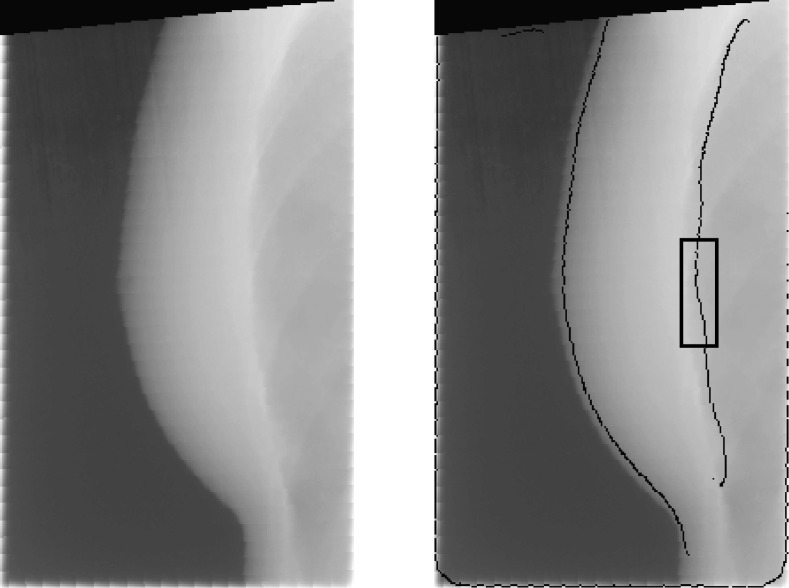
After all patients were treated, the EPID images were retrieved from the ARIA database and anonymized. Algorithms written in MATLAB were used to perform all subsequent analysis (MATLAB 7.12, The MathWorks Inc., Natick, MA). Images taken when the MLC was in use were flagged and removed, as the MLC obstructed large parts of the field of view, making it difficult to accurately measure the location of the chest wall. After removing MLC-flagged images, a Canny filter detected the position of the edge of the chest wall in each image. This algorithm set minimum and maximum pixel counts of 1310 (2% saturation) and 1966 (3% saturation), respectively. The Canny filter used a Gaussian smoothing filter with σ = 10 pixels, which removed the majority of image artifacts yet preserved the chest wall boundary (Fig. 1).
Figure 1.
(Left image) EPID image of breast and chest wall during DIBH. (Right image) The output of the Canny edge filter is overlaid. The location of the detected edge agrees with the visual estimate of chest wall location. Black box marks the region of the image used to calculate position of the chest wall.
The distance between the chest wall and the image border was measured for a region of the chest wall 60 pixels in height (Fig. 1). These 60 pixels were centered at a level on the chest wall that was equal to the level of the nipple in each EPID image. From these 60 distance measurements, the median distance Cmed and the standard deviation σC were calculated. Images with poor-quality edge detection results (defined as images with a σC > 3 pixels) were excluded from the final dataset, as well as any image in which Cmed differed from the calculated Cmed of the proceeding and subsequent images by 5 pixels or more, since such drastic differences were due to image artifacts and not actual chest wall motion.
RESULTS
Each RT treatment beam generated a series of N images. For each image, we report one measurement of the chest wall position, Cmed, which is measured relative to the image boundary. Hence, each RT beam is associated with a series of N chest wall measurements corresponding to the N images that were taken during that RT beam.
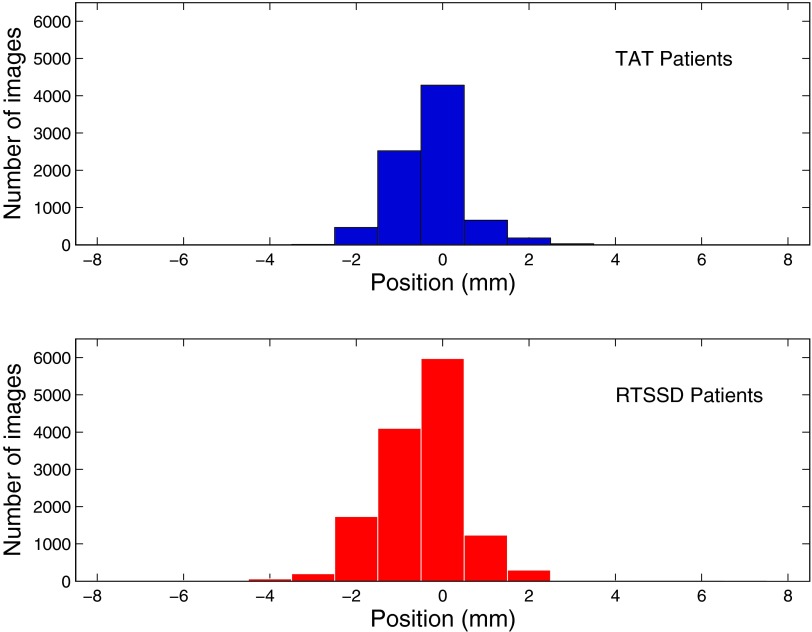
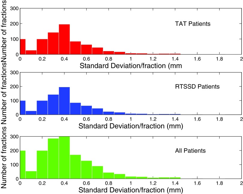
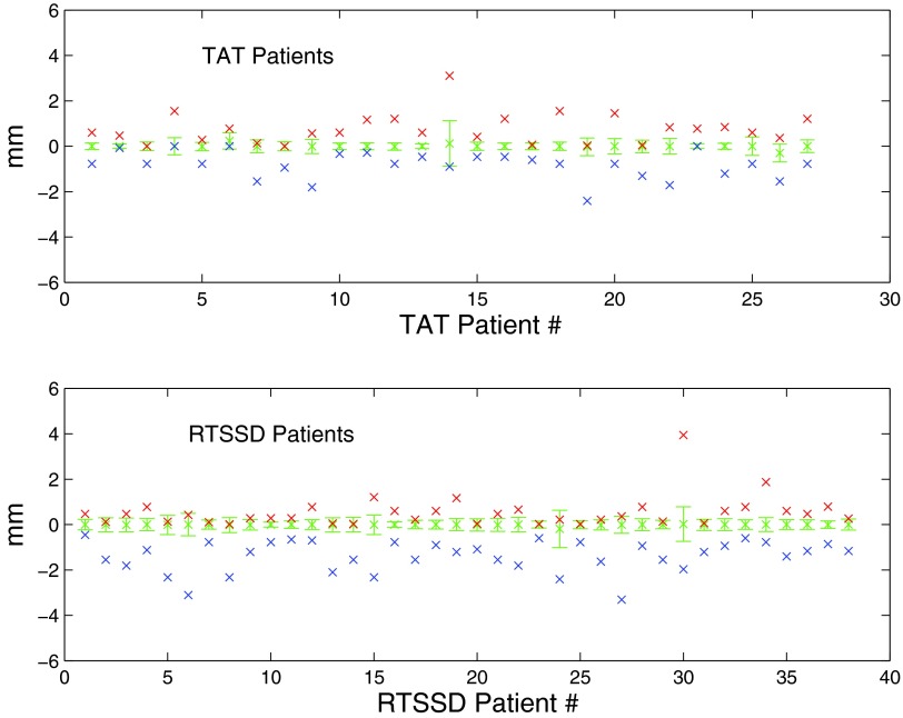
Intrabeam chest wall motion is measured by subtracting each Cmed from C0, the position of the chest wall in the first image of each beam. We represent these normalized measurements by N0 → Nn, where N0 is defined to have a value of 0 mm. Figure 2 is a histogram of N1 → Nn for all treatment beams of all patients, excluding N0 measurements, since these have a value of 0 pixels by definition. We also calculated the standard deviation σbeam of N0 → Nn for each treatment beam of each patient, which are shown as a histogram in Fig. 3. For each patient, we calculated the median, maximum, minimum, and standard deviation σpat of all measured chest wall positions (Fig. 4).
Figure 2.
Breakdown of data by images. Histogram of individual image measurements, Ni, in mm, for all treatment fractions and all patients. (Top, blue) Data from MRCC, using inroom laser, skin mark coincidence (TAT). (Bottom, red) Data from SSH, using the RTSSD device.
Figure 3.
Breakdown of data by treatment beam. Histogram of standard deviation of intrafractional motion σbeam. x-axis in mm; y-axis is number of images. (Top, red) Data from MRCC, using inroom laser, skin mark coincidence (TAT). (Middle, blue) Data from SSH, using the RTSSD device. (Bottom, green) All data.
Figure 4.
Breakdown of data by patient. Patient chest wall measurements are plotted along the x-axis. Median and standard deviation of the measured chest wall position is shown by the error bars. Crosses above the error bars represent maximum measured chest position; crosses below the error bars represent minimum measured chest position. Occasionally, the measured extrema were within the standard deviation; in these cases, the crosses overlap.
TAT patients
27 LSBC patients received RT at Milford Regional Cancer Center (TAT). The top plot in Fig. 2 is a histogram of the normalized intreatment measurements (Ni). The median normalized chest wall position, Nmed, was 0 mm. The standard deviation, σtot, was 0.67 mm. The maximum and minimum measured chest wall positions were Nmax = 3.10 mm and Nmin = −3.19 mm. 95% of Ni lies within ±0.78 mm. The distribution of Ni is slightly right-skewed, indicating the tendency of some patients to exhale slightly during beam-on.
In Fig. 3, the top plot is a histogram of σbeam for all TAT patients. The median σbeam is 0.31 mm, while the maximum σbeam is 1.35 mm, less than the 3 mm boundary set by our clinical RT protocol.
RTSSD patients
38 LSBC patients received RT at South Shore Hospital (RTSSD). The bottom plot in Fig. 2 is a histogram of the normalized intreatment measurements (Ni). The median normalized chest position, Nmed, was 0 mm. The standard deviation, σtot, was 0.92 mm. Nmax and Nmin were 3.94 and −7.76 mm, respectively. 95% of Ni lies between ±0.78 mm. Again, the data indicate a trend towards exhalation during therapy. These trends towards exhalation are a possible indictor of patient fatigue during breathhold. Shortening the breathhold period in the future may decrease or eliminate this observed trend.
In the bottom of Fig. 3, a histogram of σbeam is shown for all RTSSD patients. The median σbeam is 0.37 mm, while the maximum σbeam is 2.28 mm.
DISCUSSION
We have used cine EPID imaging on a large cohort of patients from two institutions to measure the stability of DIBH using two noncommercial surface monitoring techniques.
Our results demonstrate that both of these techniques provide a stable DIBH for RT of LSBC patients. Of the patients studied, 30 images of 4 patients measured with TAT and 280 images corresponding to 20 patients measured with RTSSD exhibited deviations greater than 3 mm at some point in their treatment, constituting 0.3% and 1.2% of the TAT and RTSSD imaging datasets, respectively.
In Fig. 2, the mean normalized chest position Nμ for TAT patients is −0.24 mm; for RTSSD patients, Nμ is −0.43 mm. However, since this difference is well below the treatment protocol's tolerance of 3 mm, there is not a clinically significant difference between the two measurement techniques. There is a negative skew in Ni evident in both patient datasets, indicating that the majority of the deviations are due to exhalation or, perhaps, muscle relaxation.
This study demonstrates the utility of EPID imaging as a way to measure patient chest wall position during DIBH, and thus as a way to retrospectively evaluate the accuracy of two noncommercial techniques to measure DIBH patient stability. We find that these two techniques, termed TAT and RTSSD, are comparable in accuracy to commercial surface imaging techniques, such as AlignRT, which have been used for DIBH verification with a reported error of 1.2–1.5 mm.14
With upgrades, EPID technology could also be used for real-time DIBH evaluation. It has been shown that the incoming EPID images can be diverted to a separate computer where they can be analyzed with a latency of 80 ms.16 In principle, the same process could be used for DIBH verification, while the treatment beam is on. The image processing and analysis techniques presented in this paper could then be used to give near real-time quantitative measurements of chest wall displacement. However, MLC modulation during beam on would present a challenge for this concept.
CONCLUSION
We used EPID images to evaluate the performance of two different surface monitoring techniques used for DIBH treatment of LSBC patients. We find that there is no clinically significant difference between these two methods, and that they are comparable with commercial surface-monitoring methods, such as AlignRT.
ACKNOWLEDGMENTS
The authors would like to acknowledge the work of the clinical staff at the Milford Regional Cancer Center and the South Shore Hospital, Dr. Lawrence Court for initiating this study.
References
- Siegel R., Naishadham D., and Jemal A., “Cancer statistics, 2013,” CA Cancer J. Clin. 63, 11–30 (2013). 10.3322/caac.21166 [DOI] [PubMed] [Google Scholar]
- Jemal A., Bray F., Center M. M., Ferlay J., Ward E., and Forman D., “Global cancer statistics,” CA Cancer J. Clin. 61, 69–90 (2011). 10.3322/caac.20107 [DOI] [PubMed] [Google Scholar]
- Clarke M. et al. , “Effects of radiotherapy and of differences in the extent of surgery for early breast cancer on local recurrence and 15-year survival: An overview of the randomised trials,” Lancet 366, 2087–2106 (2005). 10.1016/S0140-6736(05)67887-7 [DOI] [PubMed] [Google Scholar]
- Fisher B. et al. , “Twenty-year follow-up of a randomized trial comparing total mastectomy, lumpectomy, and lumpectomy plus irradiation for the treatment of invasive breast cancer,” N. Engl. J. Med. 347, 1233–1241 (2002). 10.1056/NEJMoa022152 [DOI] [PubMed] [Google Scholar]
- Cuzick J. et al. , “Cause-specific mortality in long-term survivors of breast cancer who participated in trials of radiotherapy,” J. Clin. Oncol. 12(3), 447–453 (1994). [DOI] [PubMed] [Google Scholar]
- Sardaro A., Petruzzelli M. F., D'Errico M. P., Grimaldi L., and Pili G., “Radiation-induced cardiac damage in early left breast cancer patients: Risk factors, biological mechanisms, radiobiology, and dosimetric constraints,” Radiother. Oncol. 103, 133–142 (2012). 10.1016/j.radonc.2012.02.008 [DOI] [PubMed] [Google Scholar]
- Hooning M. J., Botma A., Aleman B., Baaijens M., Bartelink H., Klijn J., Taylor C., and Leeuwen F., “Long-term risk of cardiovascular disease in 10-year survivor of breast cancer,” J. Natl. Cancer Inst. 99, 365–375 (2007). 10.1093/jnci/djk064 [DOI] [PubMed] [Google Scholar]
- Reardon K. A., Read P. W., Morris M. N., Reardon M. A., Geesey C., and Wijesooriya K. A., “Comparative analysis of 3D conformal deep inspiratory-breathhold and free-breathing intensity-modulated radiation therapy for left-sided breast cancer,” Med. Dosim. 38(2), 190–195 (2013). 10.1016/j.meddos.2013.01.002 [DOI] [PubMed] [Google Scholar]
- Vikström J., Hjelstuen M., Mjaaland I., and Dybvik K. I., “Cardiac and pulmonary dose reduction for tangentially irradiated breast cancer, utilizing deep inspiration breath-hold with audio-visual guidance, without compromising target coverage,” Acta Oncol. 50, 42–50 (2011). 10.3109/0284186X.2010.512923 [DOI] [PubMed] [Google Scholar]
- Hayden A., Rains M., and Tiver K., “Deep inspiration breath hold technique reduces heart dose from radiotherapy for left-sided breast cancer,” J. Med. Imaging Radiat. Oncol. 56, 464–472 (2012). 10.1111/j.1754-9485.2012.02405.x [DOI] [PubMed] [Google Scholar]
- Nissen H. and Appelt A., “Improved heart, lung, and target dose with deep inspiration breath hold in a large clinical series of breast cancer patients,” Radiother. Oncol. 106, 28–32 (2013). 10.1016/j.radonc.2012.10.016 [DOI] [PubMed] [Google Scholar]
- Betgen A., Alderliesten T., Sonke J., van Vliet-Vroegindeweij C., Bartelink H., and Remeijer P., “Assessment of set-up variability during deep inspiration breath hold radiotherapy for breast cancer patients by 3D-surface imaging,” Radiother. Oncol. 106, 225–230 (2013). 10.1016/j.radonc.2012.12.016 [DOI] [PubMed] [Google Scholar]
- Borst G. R., Sonke J. J., den Hollander S., Betgen A., Remeijer P., van Giersbergen A., Russell N. S., Elkhuizen P., Bartelink H., and van Vliet-Vroegindeweij, “Clinical results of image-guided deep inspiration breath hold breast irradiation,” Int. J. Radiat. Oncol., Biol., Phys. 78, 1345–1351 (2010). 10.1016/j.ijrobp.2009.10.006 [DOI] [PubMed] [Google Scholar]
- Alderliesten T., Sonke J. J., Betgen A., Honnef J., Vliet-Vroegindeweij C., and Remeijer P., “Accuracy evaluation of a 3-dimensional surface imaging system for guidance in deep-inspiration breath-hold radiation therapy,” Int. J. Radiat. Oncol., Biol., Phys. 85(2), 536–542 (2013). 10.1016/j.ijrobp.2012.04.004 [DOI] [PubMed] [Google Scholar]
- Urribarri J., Scholl K., Berbeco R., and Lingos T., “An innovative tracking device to improve left breast treatment accuracy during the deep inspiration breath hold (DIBH) technique,” Med. Phys. 38, 3857 (2011). 10.1118/1.3613525 [DOI] [Google Scholar]
- Rottmann J., Keall P., and Berbeco R., “Markerless EPID image guided dynamic multi-leaf collimator tracking for lung tumors,” Phys. Med. Biol. 58, 4195–4204 (2013). 10.1088/0031-9155/58/12/4195 [DOI] [PMC free article] [PubMed] [Google Scholar]


