Abstract
Purpose: Attenuation imaging has a promising role in the detection of tissue abnormalities. The authors have previously compared three different frequency domain ultrasound attenuation estimation methods, for accuracy and bias. The mean estimated attenuation value in a region of interest has been the determining factor of how well a method performs; however, the noise level has not been quantified for attenuation estimated using different methods.
Methods: The authors compare three different frequency domain ultrasound attenuation estimation methods [the reference phantom method (RPM), the centroid downshift method (CEN), and the hybrid method (HYB)] using the signal to noise ratio (SNR) metric. Both simulated and experimental tissue-mimicking phantoms are used in the performance comparison study, evaluating the impact of the variation in acoustical properties.
Results: For attenuation estimation in a tissue-mimicking phantom with a known attenuation coefficient of 0.5 dB/cm/MHz, all the three methods estimated the attenuation coefficient to be ≈ 0.49 dB/cm/MHz for a transmit center frequency of 6 MHz, however, the signal to noise ratio obtained was found to be 8.5, 5.7, and 2.2 for the HYB, RPM, and CEN methods, respectively. These results demonstrate the need for the SNR metric in the comparison of different algorithms and to evaluate the impact of varying different ultrasound system and tissue parameters.
Conclusions: In this paper, the authors demonstrate that although the estimated mean attenuation value with a region of interest may be closely estimated using different methods, the signal to noise ratio obtained of the estimates can vary significantly. The centroid downshift method presented with the lowest signal-to-noise ratio of the methods compared. The hybrid method was the least susceptible to changes in the acoustical properties and provided unbiased attenuation coefficient estimates with the highest signal-to-noise ratios.
Keywords: attenuation, attenuation coefficient, slope, signal-to-noise ratio, ultrasound, quantitative ultrasound
INTRODUCTION
In quantitative ultrasound (QUS) based imaging, many of the acoustic or tissue parameters such as the attenuation slope, sound speed, backscatter coefficient, effective scatterer diameter, and spacing are estimated using either frequency or time domain based approaches.1, 2, 3, 4, 5, 6, 7, 8, 9, 10, 11 Attenuation slope estimates have been used to characterize pathological tissue structures and to differentiate malignant from benign masses.2, 12, 13, 14, 15, 16, 17, 18, 19, 20, 21, 22 Accurate estimation of the attenuation slope is not only valuable as a QUS parameter, it also can reduce bias in other QUS parameters.23
Changes in the attenuation coefficient have been investigated in different organs imaged with ultrasound. For example, a study on nonalcoholic fatty liver disease indicates that the attenuation coefficient increases from 0.71 to 1.27 dB/cm/MHz with an increase in the fat content in rabbit liver.24 The attenuation coefficient has also shown the potential for in vivo breast mass differentiation, where the mean slope of the attenuation coefficient versus frequency for carcinomas was 20% greater than the mean slope value for fibroadenomas.25 In uterine and cervical ex vivo attenuation estimation, the uterine attenuation coefficient estimated at a 5 MHz center frequency was on the order of 4 dB/cm, while that in cervical tissue was on the order of 6 dB/cm.22 Since it is paramount to have accurate estimation of the attenuation slope, variations in the sound speed and backscatter intensities as well as the scatterer diameter have been evaluated to determine their impact on the accuracy and precision of different attenuation slope estimation methods.26, 27, 28
In ultrasound attenuation estimation, the mean slope value over several spectral shift or amplitude estimates are used to determine the attenuation coefficient. The estimation is done over different realizations (i.e., in a numerical phantom study a realization corresponds to an independent simulation, while for experimental data in a clinical study it corresponds to an uncorrelated data frame). Since attenuation estimation approaches differ, most of the peer-reviewed literature have primarily reported bias errors of the attenuation slope estimated within a region of interest (ROI) in uniformly attenuating simulated tissue or tissue-mimicking (TM) phantoms. Signal to noise ratio (SNR) variations in the attenuation slope estimates as a performance metric has not yet been described in the peer-reviewed literature. The SNR may provide better quantification of the performance of the attenuation estimation algorithm, enabling determination of the noise level in an attenuation image. For in vivo or patient studies, the mean estimated attenuation value is not known a priori, and the SNR could provide additional information on the noise level in order to determine the reliability of the estimated value. In this paper, we compare different attenuation slope estimation methods using the SNR computed within a ROI as the metric.
Frequency domain attenuation estimation methods utilize either the spectral shift in the power spectrum of the backscattered signal toward lower frequencies with depth, or the amplitude decay of the power spectrum as the signal propagates through tissue.5, 7 Although many frequency domain approaches have been developed, we focus on three frequency domain attenuation estimation techniques in this paper, these are: the reference phantom method (RPM), a centroid downshift method (CEN), and a hybrid method (HYB). The RPM utilizes a reference phantom with well characterized acoustic parameters to reduce diffraction effects and ultrasound system dependencies on the attenuation estimation process.7 The RPM measures the decay in the amplitude of the backscattered signal to determine the attenuation slope. The CEN approach measures the shift in the centroid of the power spectrum toward lower frequencies as the signal penetrates deeper into the scanned region.5 The HYB combines the advantages of both the RPM and CEN, by initially using the RPM approach to reduce system dependencies, and then a spectral shift approach after reintroducing the point spread function to determine the attenuation slope.3
In Secs. 2A, 2B, 2C, we first describe the theory underlying the three frequency domain approaches. We will then compute and compare SNR variations for attenuation estimates resulting from the above three frequency domain attenuation estimation techniques, for different acoustic parameters using numerical simulations and experimentally using TM phantoms using a commercial clinical ultrasound system. The acoustic parameters that are varied include the sound speed and backscatter intensity. SNR variations obtained for different ultrasound transmit center frequencies and bandwidths are also evaluated.
MATERIALS AND METHODS
Theory
Ultrasound backscattered intensity variations, denoted by I( f,z) are proportional to the system's signal transduction, transfer function T( f,z), backscatter coefficient of the medium BSC( f,z), diffraction effects D( f,z), and the total attenuation from the surface of the transducer to depth in tissue [exp(−4α( f )z)]. The ratio of the backscattered intensity in a sample to that in a reference with well characterized acoustical parameters is given by7
| (1) |
where f represents the frequency, z denotes depth, and α( f ) is the attenuation coefficient in the medium. Spectral difference approaches measure the intensity decay of the backscattered radiofrequency (RF) signal. Under the assumption that tissue can be modeled as a linear system, the RPM takes the intensity ratio of the sample phantom or tissue, Is( f, z), for which we wish to estimate the attenuation coefficient to that of a reference phantom, Ir( f, z), to reduce system dependencies. The ratio of the power spectra at two different depths is related to the attenuation of the propagating pulse as given in Eq. 1, where the subscripts s and r denote the sample and reference, respectively.
The echo signal at time t is mapped to the signal at depth z using the relationship , where c is the sound speed. The RPM assumes matched sound speeds between the reference and the sample phantoms. In addition, the sound speed used in the system's beamformer is assumed to be the same as that of the reference and the sample.7 Based on these assumptions the system dependent parameters would be significantly reduced in Eq. 1 and the resulting spectral ratio is given by
| (2) |
where RB( f ) represents the ratio of the backscattered signals and Δα( f ) is the difference in attenuation coefficients between the sample and reference. Assuming a linear variation of the attenuation with frequency,5 we get α( f ) = α × f.
Since soft tissue has the characteristics of a lowpass filter due to the increased attenuation with center frequency, the power spectrum at increased propagation depths shifts toward lower frequencies.29 Estimation of the centroid of the power spectrum at each depth, forms the basis of the centroid downshift method. Assuming that the backscattered ultrasound signal possesses a Gaussian shape with center frequency fz at depth z and variance σ2, the power spectrum Pz( f ) of the transmit signal is given by
| (3) |
where So is a constant related to the initial transmit power. Given two different depths z2 > z1, the transfer function for pulse echo propagation with attenuation α is given by Eq. 4
| (4) |
Substituting Eq. 3 in Eq. 4 and taking the natural log, provides the attenuation to depth relationship, where the power spectrum retains its shape but is centered at a lower frequency with an increase in depth as follows:
| (5) |
The centroid of the power spectrum ( fc) is calculated by taking the ratio of the first to the zeroth moment, given by Eq. 6
| (6) |
where m1 and m0 are the first and zeroth moments, respectively, f is the frequency, and X( f ) represents the Fourier transform of the backscattered ultrasound signal in the time domain.
The third method used to estimate the attenuation coefficient is a hybrid method (HYB). The hybrid method combines the advantages of the RPM and the centroid downshift method. The hybrid method first uses the RPM to remove system dependencies by using a reference phantom with well characterized acoustic parameters as given in Eq. 2. A Gaussian filter G( f ) centered at the center frequency of the transmit pulse with variance σ2 is then applied to the ratio of the signal intensities.3 The Gaussian filtered intensity ratio, GFR( f ), is given by Eq. 7
| (7) |
Equation 7 is simplified, and the expression for the attenuation coefficient reduces to the expression described in Kim and Varghese3
| (8) |
where is the derivative of the center frequency of GFR( f,z) at depth z with respect to z. As shown in Eq. 8, the hybrid method is a spectral shift method where the shift in the center frequency is detected in order to estimate the attenuation coefficient at depth z. In this paper, we set the center frequency of the Gaussian filter to be close to the center frequency of the received pulse since the backscattered signal received contains lower frequencies than the center frequency of the transmit pulse.28 The centroid of the power spectrum is calculated using the moments approach as described in Eq. 6.
Simulations and experiments
In order to calculate the SNR of the estimated attenuation maps, both simulated numerical and experimental TM phantoms were used. We used a simulation program based on the theory of continuous waves; this frequency domain program is used to generate both numerical TM phantoms and acoustic interaction.30, 31 The numerical phantoms generated in the simulations consist of glass bead scatterers that are randomly distributed; and the scatterer function is calculated from Faran's theory.32 The acoustic field for a rectangular element is determined by solving the Rayleigh integral30 and the beam focusing is accomplished by setting the phase delay of each transducer element, where the bulk attenuation coefficient and sound speed are specified, once the ultrasound field is calculated.31 The complex RF signal is generated by calculating the frequency response of the scatterers in the phantom, multiplying it with the frequency spectrum of the incident pulse; and finally applying an inverse Fourier transform.31
The simulation parameters of the numerical uniform phantoms are shown in Table 1. A fixed elevational focus was applied and set to be equal to the lateral focal point to avoid the impact of different elevational and lateral foci in the analysis. The incident pulse was simulated to be a Gaussian-shaped pulse with center frequency from 4 to 8 MHz and 50%–80% bandwidth. A single transmit focus at 40 mm was utilized for all TM numerical phantom simulations. Variations in the acoustic parameters are also evaluated.
Table 1.
Numerical simulation specifications.
| Parameters | Value |
|---|---|
| Phantom dimensions [axial, lateral, elevational] | 80 × 38 × 5 [mm] |
| Array elements and dimensions | 128 rectangular, 0.15 × 10 mm |
| Center to center element spacing | 0.2 mm |
| Number of beam lines | 190 |
| Transmit focus | 40 mm |
| Sampling rate | 40 MHz |
| Beamformer | 1540 m/s |
| Center frequency | 4, 6, 8 MHz |
| Bandwidth | 50%, 70%, 80% |
| Phantom sound speed | 1500, 1540, 1580 m/s |
| Attenuation coefficient | 0.3, 0.5, 0.7 dB/cm/MHz |
| Scatterer number density | 10, 13, 16, 20,25, 32, 40 scatterers/mm3 |
| Scatterer diameter | 10, 20, 30, 40, 50, 60, 70, 80, 90, 100 μm |
Experimental TM phantoms with sound speeds of 1533, 1500, and 1580 measured at 22 °C and posses uniform attenuation coefficients were manufactured in our laboratory. Both the sound speed and attenuation coefficients were measured in our laboratory using a narrowband substitution method.33, 34 The three phantoms used to evaluate sound speed variations consist of glass beads with diameters in the range of 5–40 μm. Two additional phantoms with similar sound speeds of 1533 m/s were used for the evaluation of scatterer diameter variations, where the scatterers consist of glass beads with diameters ranging from 75 to 90 and 125 to 150 μm, respectively (Catalog No. 3000E, Potters Industries, PA). The glass beads were randomly distributed in an agar background with scatterer concentrations of 264, 11, and 2 beads/mm3, respectively. The glass beads provide the frequency dependence of backscatter, while powdered graphite was utilized to obtain the requisite tissue-like attenuation coefficient.
The ultrasound system used to scan the experimental phantoms was a Siemens S2000 clinical ultrasound system (Siemens Medical Systems, Issaquah, WA). A VFX 9L4 linear array transducer was used for scanning with transmit center frequencies ranging from 4 to 9 MHz. The scanning depth for all the phantoms was set to 6 cm with a single focus at 3 cm. The time gain compensation (TGC) sliders were kept at the center position at all depths, and the power level was kept low (30%) to avoid saturation of the echo-signals which could lead to clipping (truncation) of the time-domain signals during digitization; adversely impacting the computation of the power spectrum. Table 2 shows the scanning parameters and the experimental uniform phantoms specifications.
Table 2.
Ultrasound system and TM phantom specifications.
| Parameters | Value |
|---|---|
| Transmit focus | 30 mm |
| Sampling rate | 40 MHz |
| Beamformer | 1540 m/s |
| Center frequency | 4, 6, 9 MHz |
| Bandwidth | 80% |
| Phantom sound speed | 1500, 1533, 1580 m/s |
| Attenuation coefficient | 0.58, 0.62, 0.72 dB/cm/MHz |
| Scatterer diameter | 5–40, 75–90, 125–150 μm |
| Scatterer number density | 264, 11, 2 beads/mm3 |
Data processing
RF data generated using the ultrasound simulation program and digitized RF data acquired from the uniformly attenuating TM phantoms were analyzed. Attenuation estimation algorithms were implemented using MATLAB (MathWorks, Inc., Natick, MA). For all three frequency domain attenuation estimation methods, the same power spectrum was utilized for analysis. We used the chirp z-transform35, 36 to calculate the power spectrum on 8 × 8 mm data blocks that were comprised of A-line segments of 8 mm along the beam direction and 38 A-lines along the lateral or perpendicular direction. The Welch method,37 was used to obtain the power spectrum, where the 8 mm A-line segment was further subdivided into 4 mm Hanning windowed segments, with a 50% overlap between the gated 4 mm segments.37 Similar analysis was performed on the adjacent A-lines within the block, and the complex Fourier spectra obtained from all the windowed segments within the 8 × 8 mm block used to obtain a stable power spectrum,37 with time averaging used to obtain the expected value for the power spectrum.38 The 4 mm Hanning windowed segment was chosen based on full width half maximum (FWHM) criteria.35 The gated window dimension were chosen to be small enough, so as to not to contradict the stationarity assumption and to provide sufficient spatial resolution. At the same time, the gated window was large enough to obtain a robust power spectrum of the backscattered RF signals,35 using Short Time Fourier Transform (STFT) based analysis. A 70% overlap of these data blocks along the beam direction was utilized to obtain spectral shift3, 5 or amplitude5, 7 estimates from consecutive power spectra, for the computation of the attenuation coefficient.
The three methods described above were used to estimate the attenuation coefficient from maps of the spectral shift or amplitude estimated.3, 5, 7 For the hybrid method, three Gaussian filters were implemented, one at the center frequency and the other two at ±0.25 MHz with respect to the center frequency. These three filters are multiplied by the normalized power spectral ratio, and the spectral shift estimates obtained were averaged and used to estimate the attenuation coefficient.
The SNR of the estimated attenuation coefficient is defined by the ratio of the mean attenuation estimated values (μ) within a ROI to the standard deviation (σ) of the estimates within the ROI
| (9) |
where n is the number of estimates in a row and m is the number of estimates in a column within an ROI. αij is the estimated attenuation in a block of the ROI.
SIMULATION RESULTS
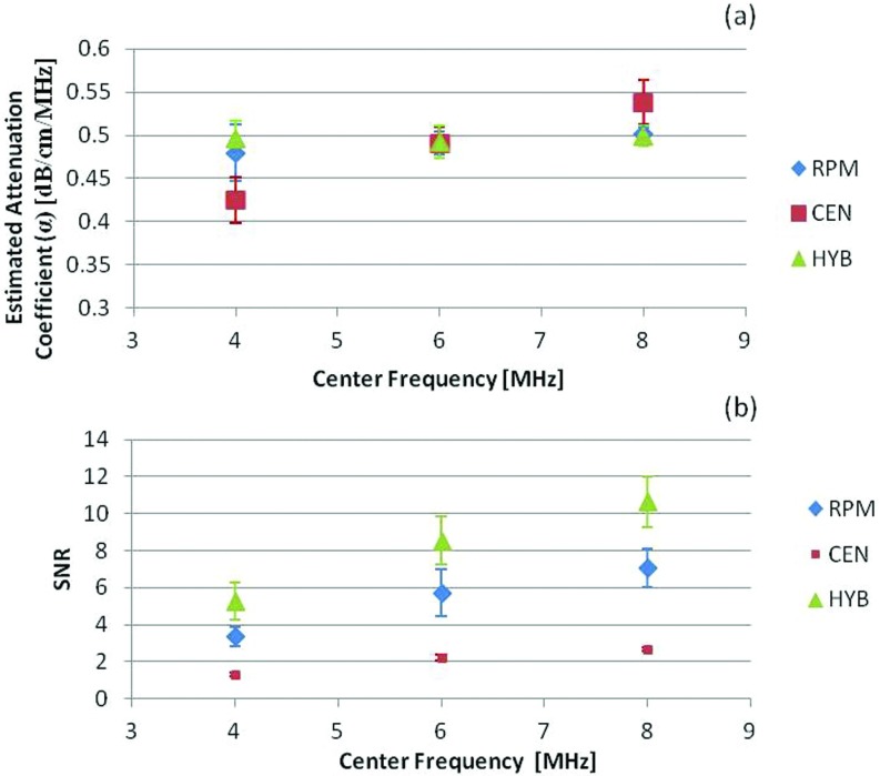
We calculate the SNR within a 2 cm ROI around the transducer focus to determine the performance of the three frequency domain methods used to estimate the attenuation coefficient from backscattered signals. We first evaluate the effect of changes in the transmit center frequency on the SNR for estimated attenuation coefficient using the three methods for an 80% bandwidth. Figure 1a presents plots of the mean and standard deviation of the attenuation coefficient estimated at center frequencies of 4, 6, and 8 MHz. Both the reference and sample phantoms were simulated with a 0.5 dB/cm/MHz attenuation coefficient, 1540 m/s sound speed, and 50 μm scatterer diameter glass beads randomly distributed in the phantom. The beam former sound speed was also set to 1540 m/s. Both the reference and sample phantom's acoustic properties were maintained the same (matched) to evaluate only the impact of the variations in the ultrasound system parameters. This matching of phantom acoustic properties, enables comparison of the SNR without other biases, especially for the RPM.7
Figure 1.
The estimated attenuation coefficient and corresponding SNR obtained using the RPM, the CEN, and the HYB using numerical simulations. The mean and standard deviation of the attenuation coefficient estimated at center frequencies of 4, 6, and 8 MHz are shown in (a), while the SNR variations are plotted in (b). The reference and sample phantoms had a 0.5 dB/cm/MHz attenuation coefficient, 50 μm scatterer diameter, and 1540 m/s sound speed.
Note from Fig. 1a, that the HYB method provides the most accurate attenuation coefficient estimate with the smallest bias and standard deviation for all the center frequencies utilized. The CEN method indicated an overestimation bias for the higher center frequency of 8 MHz and underestimation for the lower center frequency of 4 MHz, with significantly higher standard deviation. This aspect is also clearly visualized in the SNR plots shown in Fig. 1b, where the CEN method presented with the lowest SNR that reduces with an increase in the center frequency, while the HYB method provided the largest value of the SNR for all center frequencies and increased with an increase in the center frequency. The RPM method was the second best method, and provided better estimation performance than the CEN method.
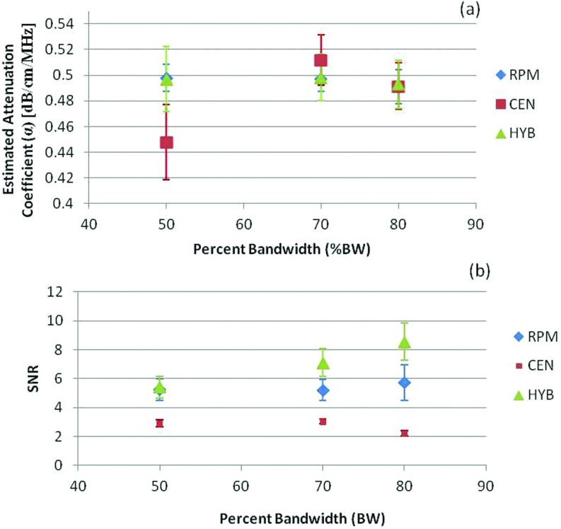
We then examined the impact of changes in the percent bandwidth (% BW) of the transmitted signal in Fig. 2. In all cases, the CEN method presented with the lowest SNR and the most bias in the attenuation estimate. The SNR increased with the % BW as shown in Fig. 2b, when RPM and HYB were used to estimate the attenuation. Plots of the attenuation coefficient estimate in Figs. 1a, 2a show that the mean attenuation slope estimates for the RPM and HYB are similar and the differences between the two estimates were statistically insignificant (p > 0.05). However, the SNR obtained [see Figs. 12b] is always higher when estimating the attenuation coefficient using the HYB method versus the RPM or CEN. The RPM is the second best method, while the performance of the CEN declined with increasing center frequency and % BW.
Figure 2.
The estimated attenuation coefficient and corresponding SNR obtained for different percent bandwidths using numerical simulations. The mean and standard deviation of the attenuation coefficient estimated at bandwidths of 50%, 70%, and 80% are shown in (a), while the SNR variations are plotted in (b).
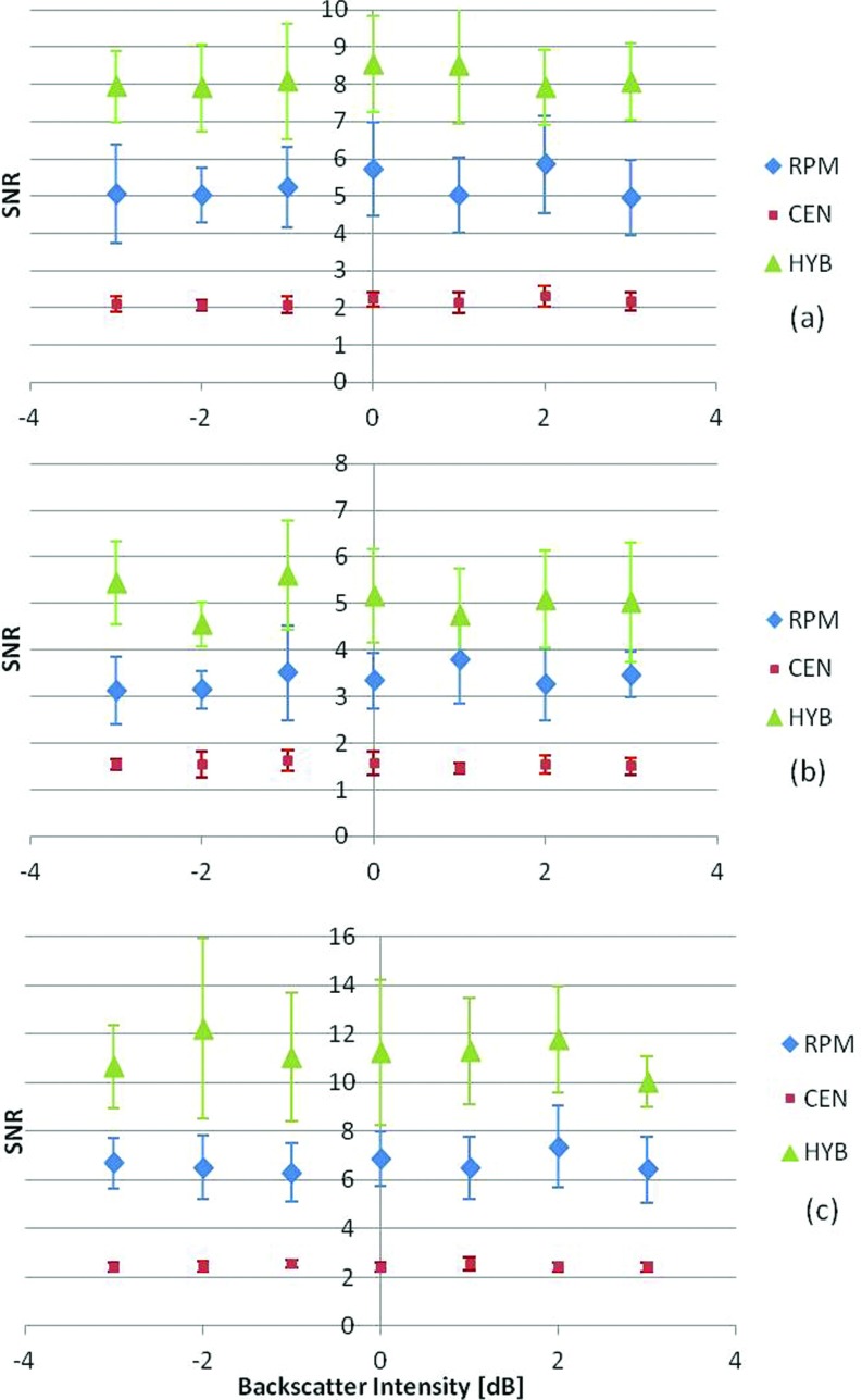
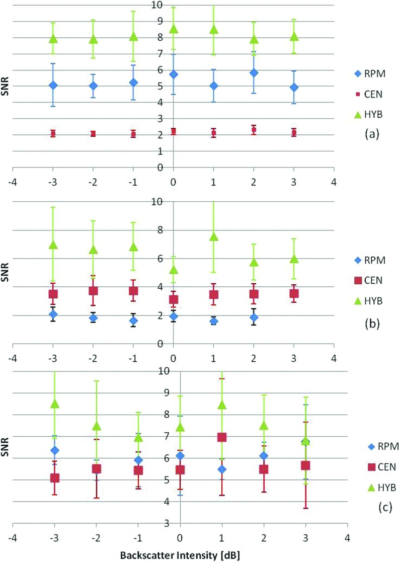
Changes in attenuation SNR with variations in the backscatter intensity are also evaluated and presented in Figs. 34. We have previously reported on the mean and standard deviation of the attenuation coefficient estimated under these conditions,28 which is also included in Tables 3, 4 in this paper. We first varied the backscatter intensity from −3 to 3 dB (10 to 40 scatterers/mm3) by varying the scatterer number density. The scatterer diameter was kept constant at 50 μm, with a 0.5 dB/cm/MHz uniform attenuation coefficient and sound speed of 1540 m/s matched between the reference and the sample phantoms. The attenuation coefficient was then estimated using the three frequency domain methods for the uniformly attenuating phantoms with three different attenuation coefficients, namely, 0.5, 0.3, and 0.7 dB/cm/MHz, as illustrated in Fig. 3. Each phantom was independently simulated ten times at each of the scatterer intensity values to obtain statistically significant results. Figure 3 presents the SNR results, with the HYB method again providing the highest SNR values among the three methods. The impact of a sound speed mismatch between the reference and the sample was also evaluated. The reference phantom's acoustic properties were kept the same, while the sound speed of the sample was changed to 1540, 1500, and 1580 m/s, respectively. Again, the SNR for the HYB method was the highest, with p < 0.05 as illustrated in Fig. 4.
Figure 3.
SNR variations for numerical TM phantoms with variations in the backscatter intensity from −3 to 3 dB with respect to the backscatter level of the reference phantom. The sound speeds in the phantoms were 1540 m/s. The sample phantom attenuation coefficients were (a) 0.5, (b) 0.3, (c) 0.7 dB/cm/MHz. In all cases, the reference phantom had a 0.5 dB/cm/MHz attenuation coefficient, 50 μm scatterer diameter, and 1540 m/s sound speed at a scatterer density of 20 scatterers/mm3. The frequency range was 2–9 MHz.
Figure 4.
Plot of the SNR variations for sample phantoms with attenuation coefficient of 0.5 dB/cm/MHz, and sample sound speed of (a) 1540, (b) 1500, (c) 1580 m/s, respectively. The backscatter intensity from −3 to 3 dB with respect to the backscatter level of the reference phantom. In all cases, the reference phantom has a 0.5 dB/cm/MHz attenuation coefficient, a 25 μm scatterer diameter, 1540 m/s sound speed, and scatterer density of 20 scatterers/mm3. The frequency range is 2–9 MHz.
Table 3.
| Figure | −3 dB | −2 dB | −1 dB | 0 dB | 1 dB | 2 dB | 3 dB | |
|---|---|---|---|---|---|---|---|---|
| 3a | RPM | 0.49 | 0.51 | 0.50 | 0.49 | 0.50 | 0.51 | 0.49 |
| CEN | 0.48 | 0.48 | 0.48 | 0.49 | 0.49 | 0.49 | 0.50 | |
| HYB | 0.48 | 0.48 | 0.48 | 0.49 | 0.48 | 0.49 | 0.49 | |
| 3b | RPM | 0.31 | 0.31 | 0.31 | 0.31 | 0.31 | 0.31 | 0.30 |
| CEN | 0.28 | 0.28 | 0.28 | 0.27 | 0.27 | 0.27 | 0.27 | |
| HYB | 0.31 | 0.30 | 0.30 | 0.30 | 0.29 | 0.30 | 0.29 | |
| 3c | RPM | 0.70 | 0.68 | 0.68 | 0.70 | 0.70 | 0.69 | 0.70 |
| CEN | 0.64 | 0.64 | 0.64 | 0.63 | 0.64 | 0.64 | 0.63 | |
| HYB | 0.66 | 0.67 | 0.67 | 0.66 | 0.67 | 0.66 | 0.66 | |
| 4a | RPM | 0.49 | 0.51 | 0.50 | 0.49 | 0.50 | 0.51 | 0.49 |
| CEN | 0.48 | 0.48 | 0.48 | 0.49 | 0.49 | 0.49 | 0.50 | |
| HYB | 0.48 | 0.48 | 0.48 | 0.49 | 0.48 | 0.49 | 0.49 | |
| 4b | RPM | 0.29 | 0.29 | 0.29 | 0.30 | 0.30 | 0.30 | 0.31 |
| CEN | 0.45 | 0.45 | 0.45 | 0.45 | 0.46 | 0.45 | 0.44 | |
| HYB | 0.48 | 0.48 | 0.47 | 0.47 | 0.49 | 0.47 | 0.47 | |
| 4c | RPM | 0.71 | 0.72 | 0.70 | 0.68 | 0.70 | 0.71 | 0.70 |
| CEN | 0.51 | 0.49 | 0.51 | 0.51 | 0.52 | 0.50 | 0.51 | |
| HYB | 0.51 | 0.49 | 0.51 | 0.50 | 0.51 | 0.50 | 0.51 |
Table 4.
| Figure | 10 | 20 | 30 | 40 | 50 | 60 | 70 | 80 | 90 | 100 | |
|---|---|---|---|---|---|---|---|---|---|---|---|
| 5a | RPM | 0.53 | 0.51 | 0.52 | 0.52 | 0.52 | 0.51 | 0.52 | 0.52 | 0.52 | 0.55 |
| CEN | 0.52 | 0.53 | 0.51 | 0.50 | 0.49 | 0.48 | 0.46 | 0.43 | 0.40 | 0.38 | |
| HYB | 0.50 | 0.51 | 0.51 | 0.50 | 0.49 | 0.50 | 0.50 | 0.49 | 0.48 | 0.48 | |
| 5b | RPM | 0.33 | 0.32 | 0.33 | 0.31 | 0.33 | 0.32 | 0.32 | 0.32 | 0.33 | 0.32 |
| CEN | 0.29 | 0.30 | 0.29 | 0.29 | 0.29 | 0.27 | 0.27 | 0.27 | 0.25 | 0.26 | |
| HYB | 0.32 | 0.33 | 0.33 | 0.33 | 0.33 | 0.32 | 0.33 | 0.35 | 0.34 | 0.34 | |
| 5c | RPM | 0.72 | 0.73 | 0.72 | 0.71 | 0.73 | 0.70 | 0.72 | 0.70 | 0.70 | 0.70 |
| CEN | 0.68 | 0.68 | 0.67 | 0.66 | 0.64 | 0.62 | 0.58 | 0.56 | 0.52 | 0.48 | |
| HYB | 0.66 | 0.67 | 0.66 | 0.67 | 0.66 | 0.65 | 0.63 | 0.64 | 0.62 | 0.61 | |
| 6a | RPM | 0.53 | 0.51 | 0.52 | 0.52 | 0.52 | 0.51 | 0.52 | 0.52 | 0.52 | 0.55 |
| CEN | 0.52 | 0.53 | 0.51 | 0.50 | 0.49 | 0.48 | 0.46 | 0.43 | 0.40 | 0.38 | |
| HYB | 0.50 | 0.51 | 0.51 | 0.50 | 0.49 | 0.50 | 0.50 | 0.49 | 0.48 | 0.48 | |
| 6b | RPM | 0.49 | 0.48 | 0.47 | 0.48 | 0.47 | 0.47 | 0.48 | 0.47 | 0.46 | 0.47 |
| CEN | 0.52 | 0.51 | 0.51 | 0.49 | 0.49 | 0.47 | 0.44 | 0.43 | 0.40 | 0.38 | |
| HYB | 0.50 | 0.50 | 0.51 | 0.50 | 0.50 | 0.50 | 0.49 | 0.50 | 0.49 | 0.48 | |
| 6c | RPM | 0.63 | 0.63 | 0.64 | 0.62 | 0.63 | 0.63 | 0.63 | 0.63 | 0.63 | 0.62 |
| CEN | 0.53 | 0.53 | 0.52 | 0.52 | 0.52 | 0.50 | 0.47 | 0.46 | 0.43 | 0.41 | |
| HYB | 0.52 | 0.52 | 0.52 | 0.52 | 0.53 | 0.52 | 0.51 | 0.51 | 0.50 | 0.50 |
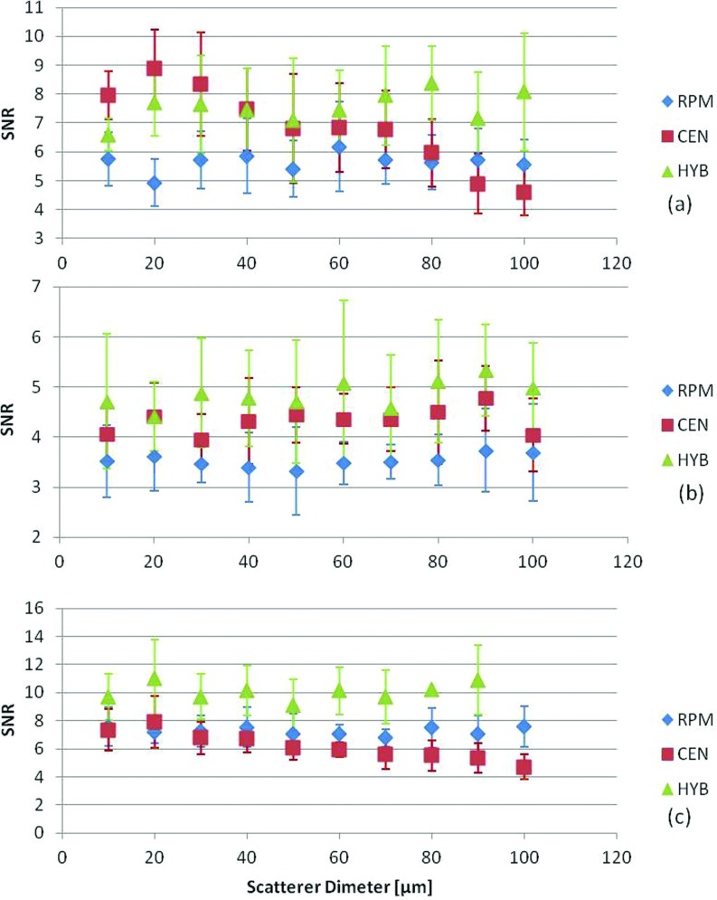
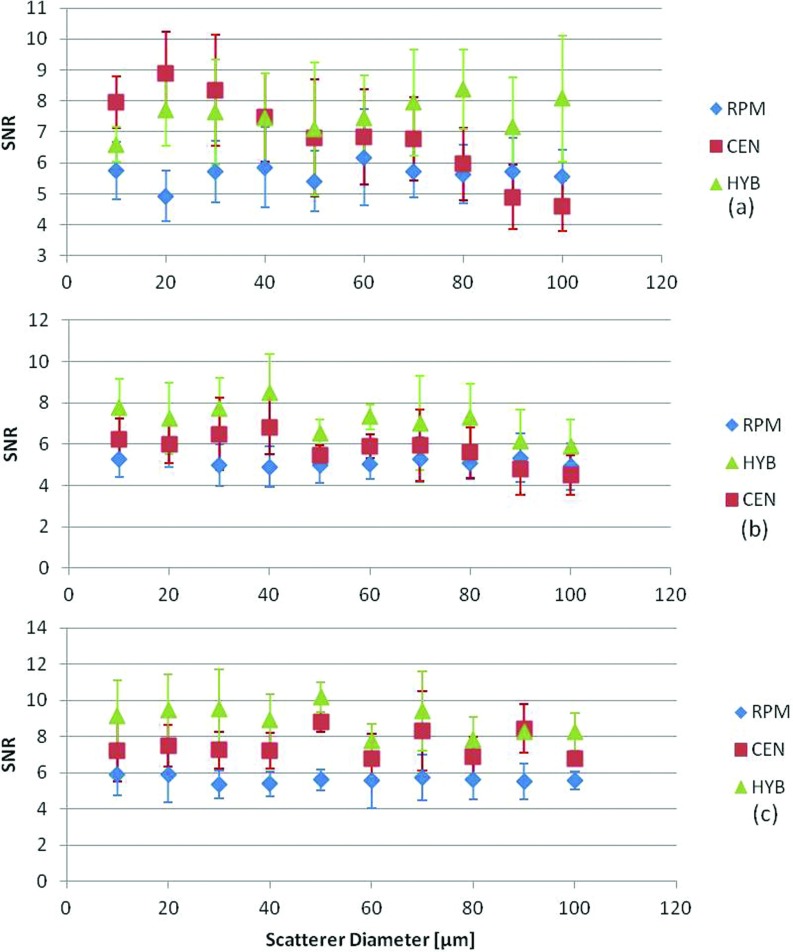
The impact of variation in the scatterer diameters that would alter the frequency dependence of scattering was performed by varying the backscatter coefficient for each scatterer diameter, in Figs. 56. We used a single scatterer diameter for each uniformly attenuating sample simulation and randomly distributed the scatterers in the medium. Scatterer diameters were varied from 10 to 100 μm. The reference phantom's acoustic properties were maintained the same throughout the estimation process with a 50 μm scatterer diameter, 1540 m/s sound speed, and 0.5 dB/cm/MHz attenuation coefficient. Figure 5, presents the results obtained for different sample attenuation coefficient values of (0.5, 0.3, and 0.7 dB/cm/MHz) while keeping all other acoustic properties constant. Figure 6 presents results where the sound speed of the samples was varied (1540, 1500, and 1580 m/s) while keeping all other acoustic properties constant. Note that for both these cases, the HYB method performed the best with the highest SNR as shown in Figs. 56, respectively.
Figure 5.
Variations in the SNR for phantoms with a sound speed of 1540 m/s, with sample attenuation coefficient of (a) 0.5, (b) 0.3, (c) 0.7 dB/cm/MHz, and scatterer diameters ranging from 10 to 100 μm. In all cases, the reference phantom has a 0.5 dB/cm/MHz attenuation coefficient, a 50 μm scatterer diameter, and 1540 m/s sound speed. The frequency range was 2–9 MHz.
Figure 6.
Variations in the SNR for sample phantoms with attenuation coefficient of 0.5 dB/cm/MHz, with sample sound speed of (a) 1540, (b)1500, (c) 1580 m/s and scatterer diameters ranging from 10 to 100 μm. In all cases, the reference phantom has a 0.5 dB/cm/MHz attenuation coefficient, a 50 μm scatterer diameter, and 1540 m/s sound speed. The frequency range was 2–9 MHz.
EXPERIMENTAL RESULTS
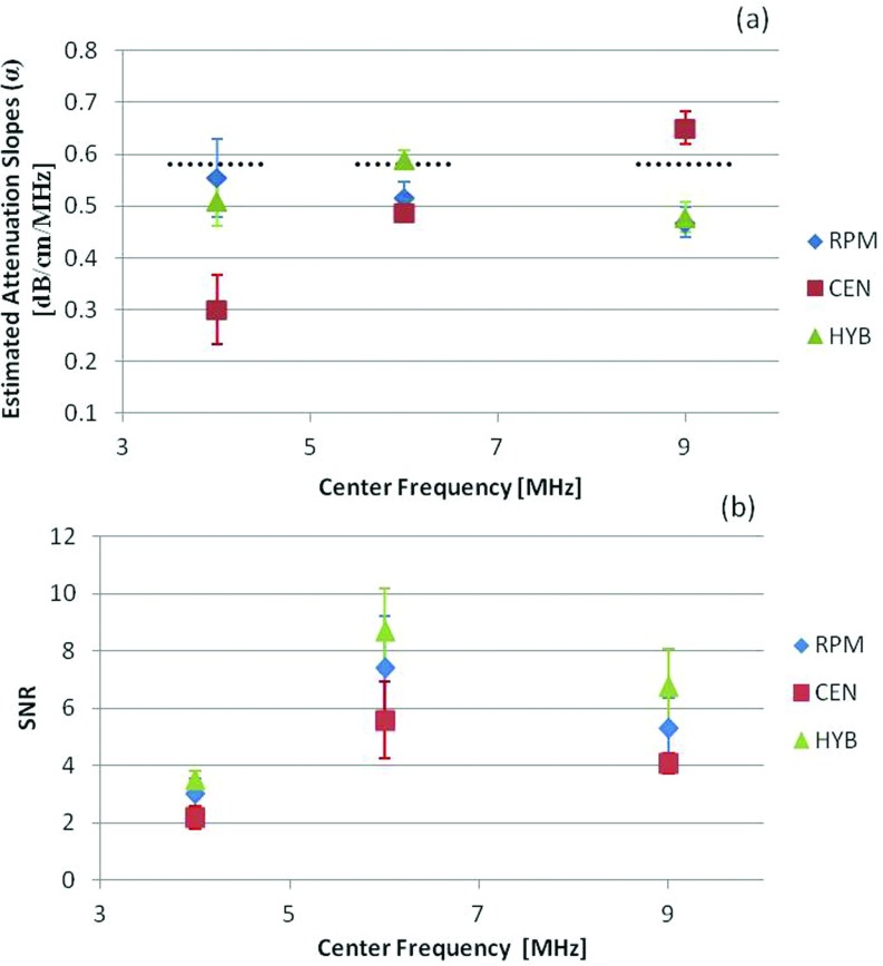
Experimental results obtained using TM phantoms are presented in this section. To evaluate SNR variations by changing the center frequency, we utilized a VFX 9L4 transducer on the Siemens S2000, with multifrequency operation in the 4–9 MHz region, and an approximately 80% bandwidth. Observe that the mean and standard deviation of the attenuation coefficient estimated using the HYB and RPM methods provided similar results, while the CEN method appears to provide biased results with increased standard deviation. The SNR increases with the center frequency for the first two center frequencies evaluated, with a slight drop in the SNR with the transducer operated at a 9 MHz in Fig. 7. We found using spectral analysis, that for the VFX 9L4 the transmitted pulse at the highest frequency was still centered around 6 MHz, which may account for the leveling of the SNR estimates shown in Fig. 7. The HYB method provided the best estimation performance of the three methods compared. Both the reference and sample phantoms were matched with a 0.58 dB/cm/MHz attenuation coefficient, 1533 m/s sound speed, and scatterers in the 75–90 μm range for the results shown in Fig. 7.
Figure 7.
The estimated attenuation coefficient and corresponding SNR obtained using experimental TM phantoms. The mean and standard deviation of the attenuation coefficient estimated at center frequencies of 4, 6, and 9 MHz using the VFX 9L4 transducer are shown in (a), while the SNR variations are plotted in (b). The dotted black line indicates the measured attenuation coefficient of the sample phantom obtained using a narrowband substitution measurement method.
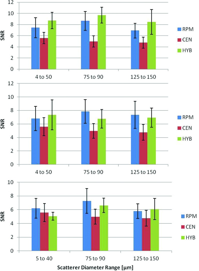
Finally, Fig. 8 presents results on three TM sample phantoms with three different scatterer diameter ranges (5–40, 75–90, and 125–150 μm), respectively. The measured sound speed in all these sample phantoms was 1533 m/s. In Fig. 8a, with a reference phantom sound speed of 1533 m/s, the HYB method provided the highest SNR for all diameter ranges. In Figs. 8b, 8c, the reference phantom's sound speed was changed to 1500 and 1580 m/s, respectively. The SNR obtained with the RPM was higher than the HYB method for some of these cases, however, since there was a sound speed mismatch between the reference and the sample the estimated mean attenuation coefficient value was closest to the actual value only with the HYB method (p < 0.05). Both the RPM and CEN methods provided biased results. The mean attenuation slope estimates were previously reported by Omari et al.,28 and are included in Table 5.
Figure 8.
Experimental SNR for the attenuation slope estimates for TM phantoms with a reference attenuation coefficient of 0.58 dB/cm/MHz and sound speeds of (a) 1533, (b)1500, and (c) 1580 m/s.
Table 5.
DISCUSSION AND CONCLUSION
In this paper, we compared the SNR variations as a quantitative metric, for attenuation slope estimated using three different frequency domain based ultrasound estimation methods. The SNR is an important metric that can be utilized to quantitatively compare the performance of different attenuation slope estimators. However, it has to be noted that these comparisons require uniformly attenuating regions, which are present in large organs, such as normal livers. Smaller uniformly attenuating regions of interest can also be utilized to estimate the SNR, as long as sufficient independent estimates are present to obtain statistically significant results. The quality of attenuation images obtained under in vivo conditions can also be better assessed when the performance of estimator can be quantitated. Attenuation estimation algorithms that provide higher SNR would generate images with lower noise levels.
Heterogeneity is often present in actual biological tissue, and variations in the attenuation coefficient under these conditions have to be addressed. Since real tissue exhibits variations in the sound speed and scatterer diameters, it is important to determine the accuracy and precision of the methods used to calculate the mean attenuation coefficient. The evaluations performed in this paper, incorporate variations in the sound speed and backscatter intensity with and without frequency dependence, to address the performance of these estimators under these conditions.
Both the reference phantom and the hybrid methods performed well when the acoustic properties of the reference and the sample were matched. We have previously reported, that both the RPM and the HYB methods perform similarly, when the sound speed of the reference and sample are matched,28 in terms of the mean and standard deviation of the attenuation coefficient estimated. The signal to noise ratio obtained with the hybrid method was the highest for all the methods evaluated in this paper. The centroid downshift method performed the worst with the signal to noise ratio being the lowest, even when the attenuation coefficient estimated was close to the actual value (low bias). These results indicate that the standard deviation of the attenuation coefficient estimates obtained using the centroid downshift method are quite large, reducing the reliability of the estimates. Low values of the SNR would therefore indicate unreliable estimation of the attenuation coefficient.
In the presence of a mismatch between the acoustic properties of the reference and the sample, the hybrid method still provided the best signal-to noise among the methods evaluated, for the numerical simulations. Our previously reported results on the mean attenuation coefficient estimates, also indicated that the hybrid method provided accurate estimation, when compared to the RPM with a sound speed mismatch between the reference and the sample.28 Although for some of the instances with a sound speed mismatch, the RPM provided a higher SNR, the attenuation coefficient estimate obtained was biased, as also reported previously.28 The hybrid method on the other hand provided unbiased attenuation coefficient estimation under all conditions.
ACKNOWLEDGMENTS
This work is funded in part by the National Institutes of Health (NIH) Grant Nos. 5R21CA140939, R01CA112192, and R01CA112192-06. E.A.O. was also supported by funds from the Mazess foundation in the Department of Medical Physics.
References
- He P. and Greenleaf J. F., “Attenuation estimation on phantoms- a stability test,” Ultrason. Imaging 8(1), 1–10 (1986). 10.1016/0161-7346(86)90019-2 [DOI] [PubMed] [Google Scholar]
- Jang H. S., Song T. K., and Park S. B., “Ultrasound attenuation estimation in soft tissue using the entropy difference of pulsed echoes between two adjacent envelope segments,” Acoust. Imaging 17, 517–531 (1989). 10.1007/978-1-4613-0791-4_55 [DOI] [PubMed] [Google Scholar]
- Kim H. and Varghese T., “Hybrid spectral domain method for attenuation slope estimation,” Ultrasound Med. Biol. 34(11), 1808–1819 (2008). 10.1016/j.ultrasmedbio.2008.04.011 [DOI] [PubMed] [Google Scholar]
- Knipp B. S., Zagzebski J. A., Wilson T. A., Dong F., and Madsen E. L., “Attenuation and backscatter estimation using video signal analysis applied to B-mode images,” Ultrason. Imaging 19(3), 221–233 (1997). 10.1177/016173469701900305 [DOI] [PubMed] [Google Scholar]
- Kuc R., “Estimating acoustic attenuation from reflected ultrasound signals- comparison of spectral-shift and spectral- difference approaches,” IEEE Trans. Acoust., Speech, Signal Process. 32(1), 1–6 (1984). 10.1109/TASSP.1984.1164282 [DOI] [Google Scholar]
- Zhao B., Basir O. A., and Mittal G. S., “Estimation of ultrasound attenuation and dispersion using short time Fourier transform,” Ultrasonics 43(5), 375–381 (2005). 10.1016/j.ultras.2004.08.001 [DOI] [PubMed] [Google Scholar]
- Yao L. X., Zagzebski J. A., and Madsen E. L., “Backscatter coefficient measurements using a reference phantom to extract depth-dpendent instrumentation factors,” Ultrason. Imaging 12(1), 58–70 (1990). 10.1016/0161-7346(90)90221-I [DOI] [PubMed] [Google Scholar]
- Wagner R. F., Insana M. F., and Brown D. G., “Unified approach to the detection and classification of speckle texture in diagnostic ultrasound,” Proc. SPIE 0556, 146–152 (1985). 10.1117/12.949534 [DOI] [PMC free article] [PubMed] [Google Scholar]
- Varghese T. and Donohue K. D., “Estimating mean scatterer spacing with the frequency-smoothed spectral autocorrelation function,” IEEE Trans. Ultrason. Ferroelectr. Freq. Control 42(3), 451–463 (1995). 10.1109/58.384455 [DOI] [Google Scholar]
- Simon C., Shen J., Seip R., and Ebbini E. S., “A robust and computationally efficient algorithm for mean scatterer spacing estimation,” IEEE Trans. Ultrason. Ferroelectr. Freq. Control 44(4), 882–894 (1997). 10.1109/58.655203 [DOI] [Google Scholar]
- Chen S. P., Tsao S.-K., and Tsao J., in Proceedings of the 4th International Conference on Biomedical Engineering and Informatics, Shanghai (BMEI) (IEEE, 2011), vol. 2, pp. 602–606. 10.1109/BMEI.2011.6098431 [DOI]
- Lin T., Ophir J., and Potter G., “Frequency-dependent ultrasonic differentiation of normal and diffusely diseased liver,” J. Acoust. Soc. Am. 82(4), 1131–1138 (1987). 10.1121/1.395303 [DOI] [PubMed] [Google Scholar]
- Parker K. J., Asztely M. S., Lerner R. M., Schenk E. A., and Waag R. C., “In vivo measurements of ultrasound attenuation in normal or diseased liver,” Ultrasound Med. Biol. 14(2), 127–136 (1988). 10.1016/0301-5629(88)90180-9 [DOI] [PubMed] [Google Scholar]
- Landini L., Sarnelli R., and Squartini F., “Frequency-dependent attenuation in breast tissue characterization,” Ultrasound Med. Biol. 11(4), 599–603 (1985). 10.1016/0301-5629(85)90031-6 [DOI] [PubMed] [Google Scholar]
- Landini L. and Sarnelli R., “Evaluation of the attenuation coefficients in normal and pathological breast tissue,” Med. Biol. Eng. Comput. 24(3), 243–247 (1986). 10.1007/BF02441619 [DOI] [PubMed] [Google Scholar]
- Duerinckx A., Rosenberg K., Hoefs J., Aufrichtig D., Colebeuglet C., Kanel G., Lottenberg S., and Ferrari L. A., “In vivo acoustic attenuation in liver - correlations with blood-tests and histology,” Ultrasound Med. Biol. 14(5), 405–413 (1988). 10.1016/0301-5629(88)90076-2 [DOI] [PubMed] [Google Scholar]
- Dong B. W., Wang M., Xie K., and Chen M. H., “In-vivo measurements of Frequency-dependent attenuation in tumors of the liver,” J. Clin. Ultrasound 22(3), 167–174 (1994). 10.1002/jcu.1870220304 [DOI] [PubMed] [Google Scholar]
- Lu Z. F., Zagzebski J. A., and Lee F. T., “Ultrasound backscatter and attenuation in human liver with diffuse disease,” Ultrasound Med. Biol. 25, 1047–1054 (1999). 10.1016/S0301-5629(99)00055-1 [DOI] [PubMed] [Google Scholar]
- McFarlin B. L., O’Brien W. D., Oelze M. L., Zachary J. F., and White-Traut R. C., “Quantitative ultrasound assessment of the rat cervix,” J. Ultrasound Med. 25(8), 1031–1040 (2006). [DOI] [PMC free article] [PubMed] [Google Scholar]
- Strowitzki M., Brand S., and Jenderka K.-V., “Ultrasonic radio-frequency spectrum analysis of normal brain tissue,” Ultrasound Med. Biol. 33(4), 522–529 (2007). 10.1016/j.ultrasmedbio.2006.09.004 [DOI] [PubMed] [Google Scholar]
- Nam K., Rosado-Mendez I. M., Wirtzfeld L. A., Pawlicki A. D., Kumar V., Madsen E. L., Ghoshal G., Lavarello R. J., Oelze M. L., Bigelow T. A., Zagzebski J. A., W. D.O’BrienJr., and Hall T. J., “Ultrasonic Attenuation and Backscatter Coefficient Estimates of Rodent-Tumor-Mimicking Structures: Comparison of Results among Clinical Scanners,” Ultrason. Imaging 33(4), 233–250 (2011). 10.1177/016173461103300403 [DOI] [PMC free article] [PubMed] [Google Scholar]
- Kiss M. Z., Varghese T., and Kliewer M. A., “Ex vivo ultrasound attenuation coefficient for human cervical and uterine tissue from 5 to 10 MHz,” Ultrasonics 51(4), 467–471 (2011). 10.1016/j.ultras.2010.11.012 [DOI] [PMC free article] [PubMed] [Google Scholar]
- Nam K., Rosado-Mendez I. M., Wirtzfeld L. A., Ghoshal G., Pawlicki A. D., Madsen E. L., Lavarello R. J., Oelze M. L., Zagzebski J. A., W. D.O’BrienJr., and Hall T. J., “Comparison of ultrasound attenuation and backscatter estimates in layered tissue-mimicking phantoms among three clinical scanners,” Ultrason. Imaging 34(4), 209–221 (2012). 10.1177/0161734612464451 [DOI] [PMC free article] [PubMed] [Google Scholar]
- Ghoshal G., Lavarello R. J., Kemmerer J. P., Miller R. J., and Oelze M. L., “Ex vivo study of quantitative ultrasound parameters in fatty rabbit livers,” Ultrasound Med. Biol. 38(12), 2238–2248 (2012). 10.1016/j.ultrasmedbio.2012.08.010 [DOI] [PMC free article] [PubMed] [Google Scholar]
- Nam K., Zagzebski J. A., and Hall T. J., “Quantitative assessment of in vivo breast masses using ultrasound attenuation and backscatter,” Ultrason. Imaging 35(2), 146–161 (2013). 10.1177/0161734613480281 [DOI] [PMC free article] [PubMed] [Google Scholar]
- Omari E., Lee H., and Varghese T., “Theoretical and phantom based investigation of the impact of sound speed and backscatter variations on attenuation slope estimation,” Ultrasonics 51(6), 758–767 (2011). 10.1016/j.ultras.2011.03.004 [DOI] [PMC free article] [PubMed] [Google Scholar]
- Labyed Y. and Bigelow T. A., “A theoretical comparison of attenuation measurement techniques from backscattered ultrasound echoes,” J. Acoust. Soc. Am. 129(4), 2316–2324 (2011). 10.1121/1.3559677 [DOI] [PMC free article] [PubMed] [Google Scholar]
- Omari E., Varghese T., Madsen E. L., and Frank G., “Evaluation of the impact of backscatter intensity variations on ultrasound attenuation estimation,” Med. Phys. 40(8), 082904 (10pp.) (2013). 10.1118/1.4816305 [DOI] [PMC free article] [PubMed] [Google Scholar]
- Fink M., Hottier F., and Cardoso J. F., “Ultrasonic signal-processing for invivo attenuation measurement -short- time fourier-analysis,” Ultrason. Imaging 5(2), 117–135 (1983). 10.1177/016173468300500202 [DOI] [PubMed] [Google Scholar]
- Yadong L. and Zagzebski J. A., “A frequency domain model for generating B-mode images with array transducers,” IEEE Trans. Ultrason. Ferroelectr. Freq. Control 46(3), 690–699 (1999). 10.1109/58.764855 [DOI] [PubMed] [Google Scholar]
- Chen Q., Computer Simulations in Parametric Ultrasonic Imaging (University of Wisconsin-Madison, Madison, 2004). [Google Scholar]
- J. J.FaranJr., “Sound scattering by solid cylinders and spheres,” J. Acoust. Soc. Am. 23, 405–417 (1951). 10.1121/1.1906780 [DOI] [Google Scholar]
- Madsen E. L., Frank G. R., Carson P. L., Edmonds P. D., Frizzell L. A., Herman B. A., Kremkau F. W., Obrien W. D., Parker K. J., and Robinson R. A., “Interlaboratory comparison of ultrasonic-attenuation and speed measurements,” J. Ultrasound Med. 5(10), 569–576 (1986). [DOI] [PubMed] [Google Scholar]
- Madsen E. L., Dong F., Frank G. R., Garra B. S., Wear K. A., Wilson T., Zagzebski J. A., Miller H. L., Shung K. K., Wang S. H., Feleppa E. J., Liu T., O’Brien W. D., Topp K. A., Sanghvi N. T., Zaitsev A. V., Hall T. J., Fowlkes J. B., Kripfgans O. D., and Miller J. G., “Interlaboratory comparison of ultrasonic backscatter, attenuation, and speed measurements,” J. Ultrasound Med. 18(9), 615–631 (1999). [DOI] [PubMed] [Google Scholar]
- Kim H. and Varghese T., “Attenuation estimation using spectral cross-correlation,” IEEE Trans. Ultrason. Ferroelectr. Freq. Control 54(3), 510–519 (2007). 10.1109/TUFFC.2007.274 [DOI] [PubMed] [Google Scholar]
- Varghese T., Konofagou E. E., Ophir J., Alam S. K., and Bilgen M., “Direct strain estimation in elastography using spectral cross-correlation,” Ultrasound Med. Biol. 26(9), 1525–1537 (2000). 10.1016/S0301-5629(00)00316-1 [DOI] [PubMed] [Google Scholar]
- Welch D., “The use of fast fourier transform for the estimation of power spectra: a method based on time averaging over short, modified periodograms,” IEEE Trans. Audio Electroacoust. 15(2), 70–73 (1967). 10.1109/TAU.1967.1161901 [DOI] [Google Scholar]
- Varghese T. and Donohue K. D., “Mean-scatterer spacing estimates with spectral correlation,” J. Acoust. Soc. Am. 96(6), 3504–3515 (1994). 10.1121/1.410611 [DOI] [PubMed] [Google Scholar]


