Abstract
Optical microangiography (OMAG) is a method that enables the non-invasive extraction of blood vessels within biological tissues. OMAG B-frames are prone to noise; therefore, techniques like B-frame averaging have been applied to reduce these effects. A drawback of this method is that the total acquisition time and amount of data collected is increased; hence, the data is susceptible to motion artifacts and de-correlation. In this paper we propose using an image filter on a non-averaged OMAG B-frame to reduce its noise. Consequently, B-frames comparable to the averaged OMAG B-frame are obtained, while reducing the total acquisition and processing time. The method is tested with two different systems, a high resolution spectral domain and a relatively low resolution swept-source optical coherence tomography (OCT) system. It is demonstrated that the weighted average filter produces the lowest B-frame error; however, all filters produce comparable results when quantifying the en face projection view image.
1. Introduction
Optical coherence tomography (OCT) is an optical imaging technology that generates cross-sectional images of biological tissues with micrometer scale resolution [1]. The OCT method is non-invasive and can be applied in vivo. OCT is based on a Michelson interferometer, which uses a broadband light source, a reference mirror in one arm, and a scanning sample on the other arm. Most recently, Fourier-domain OCT, which includes spectral domain OCT (SDOCT) (e.g. [2]) and swept-source OCT (SSOCT) (e.g. [3]), have been developed and used in both research and clinical applications.
Analogous to ultrasound imaging, OCT can capture not only the structural information, but also the functional and hemodynamic information. A variation in the data acquisition and processing of OCT images has enabled the visualization of three-dimensional (3-D) tissue angiography [4]. The non-invasive characteristics and high axial (2-15μm) and lateral (5-30μm) resolution of OCT systems are well suited to visualize in vivo vasculatures, with capillary resolution. Several types of microangiography techniques have been developed which includes optical microangiography (OMAG) [4], phase variance OCT [5-7], autocorrelation [8], correlation mapping [9,10], split-spectrum amplitude-decorrelation [11], intensity based Doppler variance [12], speckle variance [13,14], and joint spectral-time domain OCT [15,16].
These techniques require several angiography B-frames to be averaged together in order to reduce the B-frame noise. As a result, the acquisition time is increased and the images are prone to tissue motion artifacts and structural de-correlation.
In this paper we propose to improve the image quality of non-averaged OMAG (NA-OMAG) B-frames by applying an image filter; such that there is an increase in its quality to values comparable to the averaged OMAG (A-OMAG) B-frame. The tradeoff is between the image quality, and the acquisition and processing time. We present a method where image filters are trained such that they are optimized for a specific system and tissue used. We then quantify the vessel length fraction [17] of an en face projection view image, to determine the benefit of using the B-frame image filter on a NA-OMAG B-frame. The method is demonstrated using a low and a high resolution OCT system.
In this paper we focus on the OMAG technique which has successfully been developed by our research group, and applied towards imaging the eye [18,19], brain [20], kidney [21], skin [22,23] and cochlea [24,25]. However, the method can be applied to other angiography modalities.
2. System setup and experimental preparation
a. System setup
In this study we used two OCT systems to analyze the proposed method, a high-resolution SDOCT system and a relatively low-resolution SSOCT system. The SDOCT system was home built in our laboratory [26]; while the SSOCT system was a commercial product (OCS1310V1, ThorLabs, Inc.).
In an OCT system, the light from the source was split into two paths. One portion of the light was transmitted to the sample arm (the biological tissue) and the other portion was transmitted to the reference arm. In the sample arm, the light was coupled to a scanner containing a collimating lens, a XY galvanometer and an objective lens. In the reference arm, optics was used for dispersion compensation. The light returning from the reference and sample arms produced an interference pattern which was detected and processed. The SDOCT uses a spectrometer, while the SSOCT uses a balanced receiver and a high speed digitizer to detect the interference signal.
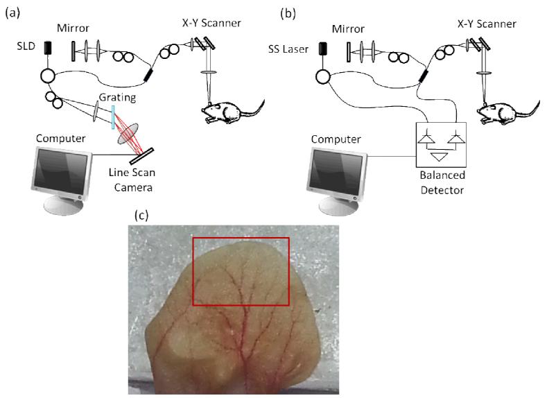
The light source of the SDOCT system has a center wavelength of 1310 nm with a 65 nm full-width half maximum (FWHM) bandwidth which provides an axial resolution of ~12μm in air. The A-scan rate was 47 kHz providing a frame rate of ~ 94 fps. The lateral resolution was estimated to be ~5.8 μm using a 10 × objective lens with an 18mm effective focal length. The system is presented in Figure 1(a). The SSOCT system has a 1300nm central wavelength of light with a 100nm bandwidth tuning range at −10dB which provides an axial resolution of < 16μm in air, based on the manufacturer specifications. The A-scan rate was 100 kHz and it was providing a frame rate of ~70 fps. The lateral resolution was ~25μm using a 25mm focal length objective lens. The system is presented in Figure 1(b).
Figure 1.
Schematic diagram of the (a) spectral domain OCT system, and (b) swept-source OCT system. SLD: super-luminescent diode, SS: swept source. (c) Photograph of the mouse pinna. The red box in the picture indicates the area imaged by the OCT system.
b. Animal preparation
Non-invasive in vivo images were acquired from the pinna of an 8 week old male hairless mouse weighing 28g. The mouse was anesthetized using 2% isoflurane (0.2 L/min O2 and 0.8 L/min air). The ear was positioned flat on a microscope glass slide. The animal was placed in supine position on a heating blanket (Harvard Apparatus). Theinternal body temperature of the animal was monitored using an intra-rectal temperature monitoring system. The experimental protocol was in compliance with the guidelines approved by the Institutional Animal Care and Use Committee (IACUC) of the University of Washington, WA.
A photograph of the mouse pinna is shown in Figure 1(c). The red square shows the large area scanned with the OCT system. The total area is estimated to be 8×5mm2 (width × height).
c. Scanning protocol
The scanning protocol was based on the three-dimensional OMAG technique [27]. The x-scanner (fast or B-scan) was driven with a saw tooth waveform, and the y-scanner (slow or C-scan) was driven with a linear function waveform. OMAG is typically performed using a step function waveform in the slow scan; however, in this application, we used a linear function given that the SSOCT system only allows this type of waveform, and at the time of this experiment a software development kit (SDK) had not been made available. The fast and slow scanners had a range of ~2.2mm each, over the sample. The B-scan contained 400 A-lines. The C-scan contained 3200 B-scans (or B-frames). In this case, eight consecutive B-frames were used to obtain one OMAG B-frame, providing a total of 400 OMAG B-frames in the C-scan.
Twelve 3-D volumes were acquired with each system (SDOCT and SSOCT) in different, but overlapping areas. The en face projection view of the 3-D data was obtained, and were stitched together to reconstruct a large area (red square in Figure 1(c)).
3. Proposed method
a. Optical microangiography
OMAG is a variation of OCT, which enables the three-dimensional acquisition of blood vessels, with capillary resolution, from biological tissue without the use of contrast agents [4,28]. The flow of cells within patent blood vessels acts as the contrast for the OMAG imaging system.
The principles of OMAG can be applied in the fast or slow axis. The fast axis is sensitive to large vessels with fast blood flow rate and the slow axis is sensitive to both fast and slow flow vessels. In this paper, the analysis was applied in the slow axis to increase the sensitivity to the capillaries. The interference signal of an A-line can be expressed as [29]:
| 1 |
where k is the wavenumber given by 2π/λ and λ is the wavelength of the light; t is the timing when an A-line is captured; ER is the light reflected from the reference mirror; S(k) is the spectral density of the light source used; n is the refractive index of tissue; z is the depth coordinate; a(z,t) is the amplitude of the back scattered light; v is the velocity of moving blood cells in a blood vessel, which is located at depth z1. Given that the light backscattered by the sample is weak compared to the light reflected from the reference mirror, we do not consider the self cross-correlation between the light backscattered from different positions within the sample. We also do not consider the DC signals because they do not contribute to useful OMAG signals.
In order to reconstruct the depth information (I(t,z)), the spectrum is Fourier transformed, and the result is a complex value signal that contains a phase (φ(t,z)) and magnitude (M(t,z)) term, and is presented here:
| 2 |
OMAG uses high pass filtering to isolate the optical signal of the static from the moving scatterers. In this data processing, the proposed approach first takes a differential operation on the captured depth signal along the C-scan direction:
| 3 |
where i represents the index of the B-scans in the C-scan direction, and N is the total number of B-frames that are averaged together. Iflow is also known as the OMAG B-frame.
OMAG can be applied on either the complex (I(t,z)) or absolute (M(t,z)) value signal. For this application, the commercial swept source system had unstable phase information; therefore, we limited the analysis for both the SDOCT and SSOCT to only using the magnitude information (as described in Equation 3), also known as intensity based OMAG.
The application of an image filter is a simple method that allows smoothing of a B-frame; i.e. it reduces the amount of intensity variations between one pixel and the next. It is commonly used to reduce the noise within a B-frame. In this study we compare several types of image filters to minimize the noise obtained from a non-averaged (N=1) OMAG method (which was previously defined as NA-OMAG), such that its B-frame quality was comparable to that from an averaged (N>1) OMAG B-frame. In this paper we used N = 7 (which we will refer to as A-OMAG), since it is a commonly used value known to provide a reduction in B-frame noise [26]. The advantage of using NA-OMAG is the decrease in the acquisition time, and the reduction in both the amount of data collected and the processing time.
b. Frame cost function
For the analysis of the B-frame, for each 3-D acquisition, we selected one of the A-OMAG B-frames as a reference B-frame, or the “gold standard” image. Therefore, we had a total of 24 reference B-frames (12 from the SDOCT and 12 from the SSOCT). The idea of an image filter is to replace each pixel value in a two-dimensional B-frame with a transformation applied to its neighboring pixels, including itself. As a result, it eliminates pixel values which are not representative of its surrounding. These filters are based upon a kernel, which represents the height and width of the neighborhood pixels to be sampled.
The goal is to select (or train) the parameters of the image filter that create the smallest cost (J) between a NA-OMAG B-frame after applying the image filter, and the reference A-OMAG B-frame. The cost is determined by an average least-squares calculation given by:
| 4 |
where M is the number of pixels in the B-frame, i is the pixel index, x(i) is a vector containing the ith pixel kernel of the NA-OMAG B-frame, y(i) is the ith pixel from the reference A-OMAG B-frame, and h is the hypothesis function (or image filter function) which is applied on the NA-OMAG pixel kernel vector. It is important to mention that the calculation of the cost function only included the pixels which had a structure image intensity value 10dB above the noise level. The rejection of low intensity valued pixels is important to avoid biasing the training results with noise data.
c. Image Filters
Four commonly used image filters were tested (average, median, Gaussian, and weighted average). For each of the filters several parameters needed to be specified. All filters required the kernel size defined which is given by two parameters, the number of pixels in the x-direction and the number of pixels in the z-direction. For each direction we tested four different values which contained 1, 3, 5 and 7 pixels. In addition to the kernel size, the Gaussian filter required the standard deviation parameter to be specified. In this case we tested six different values which were 0.1, 0.5, 1, 2, 4 and 8.
One of the B-frames from the 3-D OMAG data set was used as the training set, while the other 399 B-frames were used as the testing set. We needed to be careful to select a reference B-frame that had low noise. Some B-frames had motion artifacts present and needed to be rejected as the reference B-frame. Each filter was applied on the NA-OMAG training set B-frame. For each filter we tested the combination of all values for each parameter. For example, for the average filter we tested the 16 combinations of the kernel size (four values in the x-direction times four values in the z-direction). The values for each parameter that produced the smallest cost function for each filter were selected as the optimum parameters, and then applied on the 399 testing set B-frames.
A brief description of each filter is presented below:
i. Average Filter
Average filters can be used to remove additive noise, given that the speckle in OCT images become additive after logarithmic compression. In the case of the average filter, all the values in the vector x(i) are averaged together, while applying equal weight to each value.
ii. Median Filter
Median filters have been previously used for speckle suppression [30]. The filter selects the median value from the vector x(i).
iii. Gaussian Filter
A Gaussian filter smoothes or blurs an image using a Gaussian function. It reduces image noise as well as image details. Mathematically, applying a Gaussian filter is the same as convolving the image with a Gaussian function.
iv. Weighted Average (WA)
The weighted average (WA) filter is similar to the average filter but the values in the vector x(i) are averaged together with the weight for each value being different. To determine the optimum weight of each value we used a linear regression method. Given that we are only imaging a small area at a time, we can apply a constraint where the weights on the pixels on the left side of the ith pixel are the same as the weights of the pixels on its right side, in other words there is symmetry in the x-direction. This symmetry does not apply for top to bottom (z-direction); given that the signal of the OCT beam varies as a function of depth due to the scattering and absorbing properties of the tissue, as well as the shape of the Gaussian beam. Also, we add a bias term equal to “1” to the x(i) vector. The hypothesis function is then given by [31]:
| 5 |
where θ is the weight for each value in the x(i) vector. To determine the values of θ, we use the normal equation, given by [31]:
| 6 |
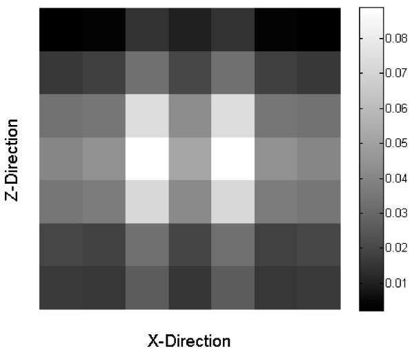
where X is a matrix that contains all the x(i) vectors for all the i pixels. The matrix X has the number of rows equal to the number of pixels in the image, and it has the number of columns equal to the size of the window plus one due to the bias term. For example, a 7×7 window size will provide 50 columns in X. Similarly the vector y is equal to the number of pixels in the image. An example of the weighted average filter θ which uses a 7×7 window size is presented in Figure 2.
Figure 2.
Example of the values used on a 7×7 window size weighted average filter.
d. Projection View Image Quantification
Usually angiography OCT images are studied by analyzing the view of the volume in the axial direction, also known as en face projection view [32]. There are several parameters that can be quantified from these images. In this study we have selected to analyze the vessel length fraction, which is a relative estimate of the length of all the vessels within the image. We selected this parameter due to its sensitivity to slow flow capillaries. The procedure has previously been described [17]. Briefly, the blood vessels are segmented from the image creating a binary mask. The binary image is then skeletonized by reducing all the vessels into linear segments with a width of 1 pixel. The lines represent the midlines of all vessel shapes. Finally, the vessel length fraction is calculated by counting the number of white pixels in the skeletonized binary image and dividing it by the total number of pixels in the image.
4. Experimental results
a. Filtering the B-frame noise
In Figure 3(a) and (b), we present a structural and flow cross-section B-frame of the mouse pinna, respectively, using the SDOCT system which was processed with A-OMAG. The flow image is one of the examples used as a reference B-frame. The total B-frame spans a horizontal range of 2.2mm.
Figure 3.
Cross-sectional (a) structural and (b) OMAG B-frame image of the mouse pinna using the SDOCT system, and processed with the A-OMAG method. The white line is 500μm.
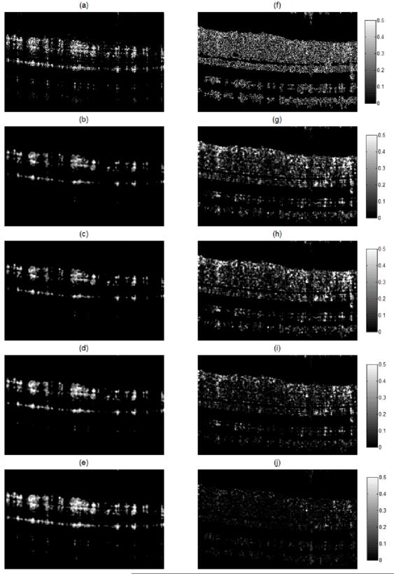
The reference B-frame was obtained by averaging seven OMAG B-frames. The first of the seven OMAG B-frames was used as the training B-frame and was defined as the NA-OMAG B-frame. We applied all the different filters to this image, and for each filter we tested all the combination of values for each parameter. The values for the parameters that provided the lowest cost function were used as the “optimum” parameters. Examples of these B-frames before and after applying each filter with the optimum parameters are observed in Figure 4(a-e). Also, Figure 4(f-j) presents the squared difference between each of the B-frames and the reference B-frame (Figure 3(b)). Visually, it can be observed that the WA filter provides the smallest squared errors. The optimum WA filter for this B-frame is shown in Figure 2.
Figure 4.
Cross-sectional flow image for the NA-OMAG (a) with no filter, and with an (b) average, (c) Gaussian, (d) median and (e) weighted average filter. Squared difference between the A-OMAG B-frame (Figure 3b) and the NA-OMAG B-frame (f) with no filter, and the (g) average, (h) Gaussian, (i) median, and (j) weighted average filter. The images were captured with an SDOCT system.
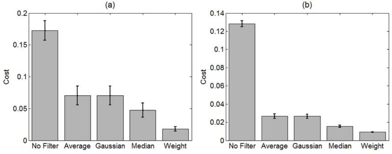
To determine that the filters and parameters obtained were not over-fitting the data, we used the other 399 NA-OMAG B-frames in the data set and determined their average and standard deviation cost function. The results are presented in Figure 5 for both the SDOCT and SSOCT systems. The cost values obtained in the testing set where comparable to the values obtained in the training set, indicating that the method was not over-fitting the data. For both systems, the WA filter presented the lowest cost.
Figure 5.
Mean and standard deviation of the cost function (Equation 4) of the training set after applying no filter, average, Gaussian, median and weighted average filter on the NA-OMAG B-frames. The results were obtained from the (a) SDOCT and (b) SSOCT systems.
b. Projection view quantification
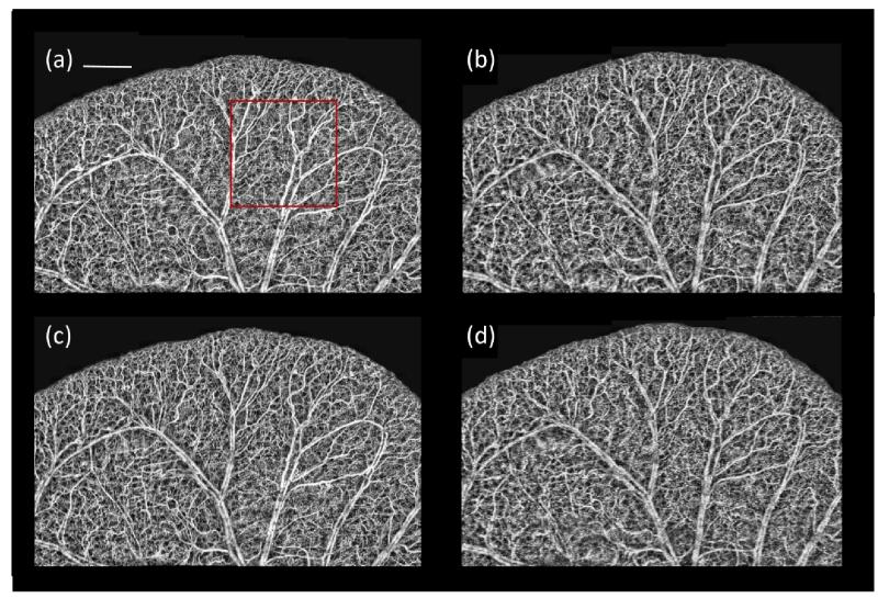
For each of the twelve three-dimensional images from each system, we obtained its projection view and applied a Rayleigh contrast-limited adaptive histogram equalization [33] to improve the uniformity of the images. The twelve projection view images from each systemwere stitched together to obtain a large area of size 5×8mm2 (red box in Figure 1(c)). These are presented in Figure 6.
Figure 6.
En face large image projection view of the mouse pinna after stitching twelve acquired areas. The image was obtained from the selected region in Figure 1c. SDOCT images created using (a) A-OMAG B-frames and (c) weighted average filter applied over NA-OMAG B-frames. SSOCT images created using (b) A-OMAG B-frames and (d) weighted average filter applied over NA-OMAG B-frames. White line is 1mm. The red square indicates a typical 2.2 × 2.2 mm area.
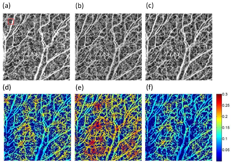
Figure 7(a-c) presents a close up version of the image presented in Figure 6(a) within the red square for the A-OMAG, the NA-OMAG and the WA filter, respectively. Similarly, the vessel length fraction [17] was quantified for each image and presented in Figure 7(d-f). To simplify the ease of view, the image was multiplied by a binary mask of the original image [17]. The images shown are for the SDOCT system; however, the images with all the filters for both SDOCT and SSOCT systems were also obtained (data not shown).
Figure 7.
Close up of the red square area in Figure 6(a) of the SDOCT system with the (a) A-OMAG, (b) NA-OMAG with no filter and (c) NA-OMAG with weighted average filter. Vessel length fraction multiplied by the black and white binary vessel image of the (d) A-OMAG, (e) NA-OMAG with no filter and (f) NA-OMAG with weighted average filter. Red square in (a) is the window size that calculates the vessel length fraction.
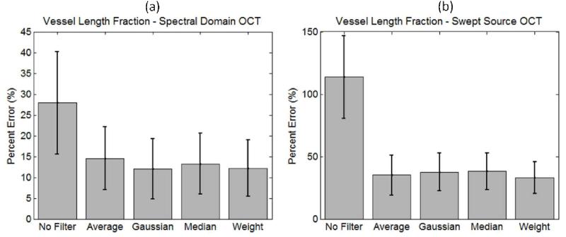
The average and standard deviation of the vessel length fraction percentage error was calculated between all the NA-OMAG images with different filters and the reference A-OMAG image. The results for both systems are presented in Figure 8.
Figure 8.
Average and standard deviation of the percentage error between the vessel length fraction calculated over the NA-OMAG image with different filters and the A-OMAG image using both systems, the (a) SDOCT and (b) SSOCT systems.
5. Discussion
Figure 3 presents examples of a cross-sectional structure and A-OMAG B-frame from the SDOCT system. The A-OMAG B-frame was used as the reference B-frame to train the filters used on the NA-OMAG B-frame. Ideally, a reference B-frame would not present noise or artifacts. Although averaging several B-frames for the A-OMAG reference B-frame can reduce the noise level, it is not an idealB-frame. As a result, the reference B-frame is slightly biased given that it will always contain some level of noise and artifacts.
Figure 4(a) presents the NA-OMAG B-frame from the same cross-section as the B-frame in Figure 3(b). The squared error difference between the two B-frames is presented in Figure 4(f), where the error in the B-frame can be visualized at each pixel. The goal is to apply an image filter on the NA-OMAG B-frame, and obtain an image as close as possible to Figure 3(b), which was determined by selecting the filter that provides the smallest square error. Figure 4 also presents the NA-OMAG B-frame after applying the average, Gaussian, median and weighted average filter, and the calculated squared error with the reference B-frame. It can be visually observed that the WA filter presented the smallest error values (Figure 4(j) is the darkest of the error B-frames).
Figure 5 presents the mean and standard deviation of the mean squared-error or cost of the 399 testing B-frames for each of the filters using both the SDOCT and SSOCT system. Similar results were obtained for all of the 24 areas that were captured with the system. These results demonstrate that the WA filter has the smallest error not only for the training set, but also for the testing set; which demonstrated its validity and usefulness. Overall, the cost of the SDOCT system is higher than that of the SSOCT system. We attribute this difference to the system resolutions. The resolution of the SSOCT system is lower than the SDOCT; therefore, the B-frames appear more blurry. The spatial filters tend to blur the B-frames and reduce its spatial resolution. As a result, after applying a filter (or blurring) the NA-OMAG B-frame, it can appear similar to a low resolution A-OMAG B-frame, compared to its high resolution counterpart. Also, the B-frames with higher resolution are more sensitive to motion artifacts; therefore, after training the data with a reference B-frame, there are more errors when applying the filter in less ideal B-frames that are affected by the movement.
We also notice that the standard deviation of the SDOCT system is larger compared to the SSOCT. We believe this occurs because we trained the filter using the whole B-frame; however, the focal length of the SDOCT is much smaller than the SSOCT. As a result, a smaller number of pixels from the SDOCT B-frame are within the focal spot; therefore, we may be using out of focus pixels as part of the training, which contributes to the error.
Figure 6 presents the large area (5×8mm2) of the mouse pinna after stitching together the individual 2.2×2.2mm2 projection view images that were captured with both systems. The results for the A-OMAG and NA-OMAG with the WA filter are presented. It is observed that the large vessels match very well with the vessels observed in the picture of Figure 1(c). Also, from this large view, it is difficult to visualize big differences between the A-OMAG, and the NA-OMAG with the weighted average filter. However, there are more noticeable differences between the SDOCT and SSOCT systems at the capillary level, where the SDOCT shows clearer capillaries, while the SSOCT presents less sharp details. This is expected given that the SSOCT system has lower resolution.
Figure 7(a-c) presents a close up version of a 2.2×2.2mm2 of the red square shown in Figure 6(a), for the A-OMAG, NA-OMAG and weighted average filter, respectively. This image allows us to perceive more details of the small capillaries. NA-OMAG (Figure 7(b)) has more noise compared to the A-OMAG (Figure 7(a)); however, this is improved by applying the WA filter (Figure 7(c)). Typically, these images are used to obtain quantitative information for studying different diseases (such as wound healing [32] or skin burn[23]). Figure 7(d-f) presents the calculation of the vessel length fraction for each of the images shown in Figure 7(a-c). The image was multiplied by a binary mask obtained from Figure 7(a-c) for ease of visualization. It is noted that the vessel length fraction calculated for A-OMAG resembles more closely the image with the weighted average filter than the NA-OMAG with no filter. This indicates that the application of an image filter on the B-frame improves the projection view image for which parameters can be quantified.
Figure 8 presents the average and standard deviation of the percentage error between each pixel of the vessel length fraction obtained from each filter on the NA-OMAG, with the vessel length fraction obtained from the A-OMAG for both systems. When no filter is used, the errors are large; however, when an image filter is applied, the errors are significantly reduced. A surprising result is that although each filter had a different cost function in the B-frame (Figure 5), the results were not significantly different when calculating the vessel length fraction on the projection view image. This allows us to conclude that for projection view image analysis, any B-frame image filter could be used with no specific advantage observed among them.
The other observation is that the errors on the SDOCT system before and after the use of the image filter were lower compared to the SSOCT system. We attribute this to the resolution of the system. Given that the capillaries are clearly observed with a high resolution system (SDOCT), the calculation of the vessel length fraction is more precise, even with the presence of noise.
In this study, we tested a few basic image filters. It is observed that the weighted average filter (Figure 2) can have any shape (as long as it is symmetrical in the x-direction); however, this shape will be different for each three-dimensional volume captured. The shape will depend on the optical properties of the tissue, the system resolution and the scanning pattern (i.e. how many A-lines per B-frame, and the spacing between A-lines).
The filters proposed do not take into account the Gaussian beam shape of the OCT laser. The filters could be improved by implementing a depth dependent variable; however, this analysis is beyond the scope of this study. Also, we did not test more advanced filter options, or the use of a combination of filters. Therefore, there is still room to explore how to obtain better B-frames when using NA-OMAG. Although in this study we concluded that all filters worked equally well when analyzing the projection view images; it is still possible to provide an image filter that would improve the calculations of the vessel length fraction, or other quantifiable parameters.
Based on these results, we envision an acquisition protocol that consists of capturing several OMAG B-frames at one position which can be used to obtain the reference B-frame to train the filter. This will then be followed by the acquisition of a single OMAG B-frame at each of the other positions in the C-direction; therefore, reducing the total acquisition time and data collected.
6. Conclusion
In this work we demonstrate that an image filter can be applied on a NA-OMAG B-frame to reduce the noise and improve its image quality to be comparable to that of an A-OMAG B-frame. The method requires the filter parameters to be trained with a reference B-frame. The main advantages are that the acquisition and processing times are significantly reduced. In this study there is a reduction of ~75% in acquisition time and data collected. Several imaging filters were compared and it is demonstrated that a WA filter has smaller squared errors with the reference B-frame compared to alternatives. It was also demonstrated that the use of a filter is beneficial for obtaining projection view images that are used for quantification (i.e. vessel length fraction). However, all the filters proposed had similar results indicating that there was no clear benefit of one filter over another. The results were validated using a low and high resolution OCT Fourier domain OCT system.
Acknowledgements
This work was supported in part by research grants from the National Institutes of Health (Grant Nos. R01HL093140, R01EB009682, and R01DC01201). The content is solely the responsibility of the authors and does not necessarily represent the official views of grant-giving bodies.
Footnotes
OCIS Code: 170.4500, 170.6900, 170.3010, 170.6930
References
- [1].Schmitt JM. Optical coherence tomography (OCT): a review. IEEE J. Sel. Top. Quantum Electron. 1999;5(4):1205–1215. doi: 10.1109/2944.796347. [doi:10.1109/2944.796348] [DOI] [PMC free article] [PubMed] [Google Scholar]
- [2].de Boer JF, Cense B, Park BH, Pierce MC, Tearney GJ, Bouma BE. Improved signal-to-noise ratio in spectral-domain compared with time-domain optical coherence tomography. Opt. Lett. 2003;28(21):2067. doi: 10.1364/ol.28.002067. OSA. doi:10.1364/OL.28.002067. [DOI] [PubMed] [Google Scholar]
- [3].Choma M, Sarunic M, Yang C, Izatt J. Sensitivity advantage of swept source and Fourier domain optical coherence tomography. Opt. Express. 2003;11(18):2183–2189. doi: 10.1364/oe.11.002183. [DOI] [PubMed] [Google Scholar]
- [4].Wang RK, Jacques SL, Ma Z, Hurst S, Hanson SR, Gruber A. Three dimensional optical angiography. Opt. Express. 2007;15(7):4083. doi: 10.1364/oe.15.004083. OSA. doi:10.1364/OE.15.004083. [DOI] [PubMed] [Google Scholar]
- [5].Fingler J, Zawadzki RJ, Werner JS, Schwartz D, Fraser SE. Volumetric microvascular imaging of human retina using optical coherence tomography with a novel motion contrast technique. Opt. Express. 2009;17(24):22190. doi: 10.1364/OE.17.022190. OSA. doi:10.1364/OE.17.022190. [DOI] [PMC free article] [PubMed] [Google Scholar]
- [6].Yu L, Chen Z. Doppler variance imaging for three-dimensional retina and choroid angiography. J. Biomed. Opt. 2010;15(1):016029. doi: 10.1117/1.3302806. doi:10.1117/1.3302806. [DOI] [PMC free article] [PubMed] [Google Scholar]
- [7].Zhao Y, Chen Z, Saxer C, Shen Q, Xiang S, de Boer JF, Nelson JS. Doppler standard deviation imaging for clinical monitoring of in vivo human skin blood flow. Opt. Lett. 2000;25(18):1358. doi: 10.1364/ol.25.001358. OSA. [DOI] [PubMed] [Google Scholar]
- [8].Wang Y, Wang R. Autocorrelation optical coherence tomography for mapping transverse particle-flow velocity. Opt. Lett. 2010;35(21):3538. doi: 10.1364/OL.35.003538. OSA. [DOI] [PMC free article] [PubMed] [Google Scholar]
- [9].Enfield J, Jonathan E, Leahy M. In vivo imaging of the microcirculation of the volar forearm using correlation mapping optical coherence tomography (cmOCT) Biomed. Opt. Express. 2011;2(5):1184–1193. doi: 10.1364/BOE.2.001184. OSA. doi:10.1364/BOE.2.001184. [DOI] [PMC free article] [PubMed] [Google Scholar]
- [10].Jonathan E, Enfield J, Leahy MJ. Correlation mapping method for generating microcirculation morphology from optical coherence tomography (OCT) intensity images. J. Biophotonics. 2011;4(9):583–587. doi: 10.1002/jbio.201000103. doi:10.1002/jbio.201000103. [DOI] [PubMed] [Google Scholar]
- [11].Jia Y, Tan O, Tokayer J, Potsaid B, Wang Y, Liu JJ, Kraus MF, Subhash H, Fujimoto JG, et al. Split-spectrum amplitude-decorrelation angiography with optical coherence tomography. Opt. Express. 2012;20(4):4710. doi: 10.1364/OE.20.004710. Optical Society of America. [DOI] [PMC free article] [PubMed] [Google Scholar]
- [12].Liu G, Lin AJ, Tromberg BJ, Chen Z. A comparison of Doppler optical coherence tomography methods. Biomed. Opt. Express. 2012;3(10):2669. doi: 10.1364/BOE.3.002669. OSA. doi:10.1364/BOE.3.002669. [DOI] [PMC free article] [PubMed] [Google Scholar]
- [13].Mariampillai A, Standish BA, Moriyama EH, Khurana M, Munce NR, Leung MKK, Jiang J, Cable A, Wilson BC, et al. Speckle variance detection of microvasculature using swept-source optical coherence tomography. Opt. Lett. 2008;33(13):1530. doi: 10.1364/ol.33.001530. OSA. doi:10.1364/OL.33.001530. [DOI] [PubMed] [Google Scholar]
- [14].Mariampillai A, Leung MKK, Jarvi M, Standish BA, Lee K, Wilson BC, Vitkin A, Yang VXD. Optimized speckle variance OCT imaging of microvasculature. Opt. Lett. 2010;35(8):1257. doi: 10.1364/OL.35.001257. OSA. [DOI] [PubMed] [Google Scholar]
- [15].Szkulmowski M, Szkulmowska A, Bajraszewski T, Kowalczyk A, Wojtkowski M. Flow velocity estimation using joint Spectral and Time domain Optical Coherence Tomography. Opt. Express. 2008;16(9):6008. doi: 10.1364/oe.16.006008. OSA. doi:10.1364/OE.16.006008. [DOI] [PubMed] [Google Scholar]
- [16].Szkulmowski M, Grulkowski I, Szlag D, Szkulmowska A, Kowalczyk A, Wojtkowski M, Optical Society of America Flow velocity estimation by complex ambiguity free joint Spectral and Time domain Optical Coherence Tomography. Opt. Express. 2009;17(16):14281. doi: 10.1364/oe.17.014281. doi:10.1364/OE.17.014281. [DOI] [PubMed] [Google Scholar]
- [17].Reif R, Qin J, An L, Zhi Z, Dziennis S, Wang RK. Quantifying optical microangiography images obtained from a spectral domain optical coherence tomography system. Int. J. Biomed. Imaging. 2012;509783 doi: 10.1155/2012/509783. [DOI] [PMC free article] [PubMed] [Google Scholar]
- [18].Li P, An L, Reif R, Shen TT, Johnstone M, Wang RK, OSA In vivo microstructural and microvascular imaging of the human corneo-scleral limbus using optical coherence tomography. Biomed. Opt. Express. 2011;2(11):3109–3118. doi: 10.1364/BOE.2.003109. doi:10.1364/BOE.2.003109. [DOI] [PMC free article] [PubMed] [Google Scholar]
- [19].An L, Li P, Shen TT, Wang R, OSA High speed spectral domain optical coherence tomography for retinal imaging at 500,000 A-lines per second. Biomed. Opt. Express. 2011;2(10):2770–2783. doi: 10.1364/BOE.2.002770. doi:10.1364/BOE.2.002770. [DOI] [PMC free article] [PubMed] [Google Scholar]
- [20].Jia Y, Alkayed N, Wang RK. Potential of optical microangiography to monitor cerebral blood perfusion and vascular plasticity following traumatic brain injury in mice in vivo. J. Biomed. Opt. 2009;14(4):040505. doi: 10.1117/1.3207121. doi:10.1117/1.3207121. [DOI] [PMC free article] [PubMed] [Google Scholar]
- [21].Zhi Z, Jung Y, Jia Y, An L, Wang RK, OSA Highly sensitive imaging of renal microcirculation in vivo using ultrahigh sensitive optical microangiography. Biomed. Opt. Express. 2011;2(5):1059–1068. doi: 10.1364/BOE.2.001059. doi:10.1364/BOE.2.001059. [DOI] [PMC free article] [PubMed] [Google Scholar]
- [22].Qin J, Jiang J, An L, Gareau D, Wang RK. In vivo volumetric imaging of microcirculation within human skin under psoriatic conditions using optical microangiography. Lasers Surg. Med. 2011;43(2):122–129. doi: 10.1002/lsm.20977. doi:10.1002/lsm.20977. [DOI] [PMC free article] [PubMed] [Google Scholar]
- [23].Qin J, Reif R, Zhi Z, Dziennis S, Wang R. Hemodynamic and morphological vasculature response to a burn monitored using a combined dual-wavelength laser speckle and optical microangiography imaging system. Biomed. Opt. Express. 2012;3(3):455–466. doi: 10.1364/BOE.3.000455. OSA. doi:10.1364/BOE.3.000455. [DOI] [PMC free article] [PubMed] [Google Scholar]
- [24].Dziennis S, Reif R, Zhi Z, Nuttall AL, Wang RK. Effects of hypoxia on cochlear blood flow in mice using Doppler optical microangiography. J. Biomed. Opt. 2012;17(10):106003. doi: 10.1117/1.JBO.17.10.106003. doi:10.1117/1.JBO.17.10.106003. [DOI] [PMC free article] [PubMed] [Google Scholar]
- [25].Reif R, Qin J, Shi L, Dziennis S, Zhi Z, Nuttall AL, Wang RK. Monitoring Hypoxia Induced Changes in Cochlear Blood Flow and Hemoglobin Concentration Using a Combined Dual-Wavelength Laser Speckle Contrast Imaging and Doppler Optical Microangiography System. In: Muñoz-Barrutia A, editor. PLoS One. 12. Vol. 7. Public Library of Science; 2012. p. e52041. doi:10.1371/journal.pone.0052041. [DOI] [PMC free article] [PubMed] [Google Scholar]
- [26].Yousefi S, Qin J, Wang RK, Optical Society of America Super-resolution spectral estimation of optical micro-angiography for quantifying blood flow within microcirculatory tissue beds in vivo. Biomed. Opt. Express. 2013;4(7):1214. doi: 10.1364/BOE.4.001214. doi:10.1364/BOE.4.001214. [DOI] [PMC free article] [PubMed] [Google Scholar]
- [27].An L, Qin J, Wang RK, OSA Ultrahigh sensitive optical microangiography for in vivo imaging of microcirculations within human skin tissue beds. Opt. Express. 2010;18(8):8220–8228. doi: 10.1364/OE.18.008220. doi:10.1364/OE.18.008220. [DOI] [PMC free article] [PubMed] [Google Scholar]
- [28].Reif R, Wang RK. Label-free imaging of blood vessel morphology with capillary resolution using optical microangiography. Quant. Imaging Med. Surg. 2012;2(3):207–212. doi: 10.3978/j.issn.2223-4292.2012.08.01. [DOI] [PMC free article] [PubMed] [Google Scholar]
- [29].Wang RK, An L, Optical Society of America Doppler optical micro-angiography for volumetric imaging of vascular perfusion in vivo. Opt. Express. 2009;17(11):8926. doi: 10.1364/oe.17.008926. doi:10.1364/OE.17.008926. [DOI] [PMC free article] [PubMed] [Google Scholar]
- [30].Ozcan A, Bilenca A, Desjardins AE, Bouma BE, Tearney GJ, Optical Society of America Speckle reduction in optical coherence tomography images using digital filtering. J. Opt. Soc. Am. A. 2007;24(7):1901. doi: 10.1364/josaa.24.001901. doi:10.1364/JOSAA.24.001901. [DOI] [PMC free article] [PubMed] [Google Scholar]
- [31].Abu-Mostafa YS, Magdon-Ismail M, Lin H-T. Learning From Data. AMLBook. 2012 [Google Scholar]
- [32].Jung Y, Dziennis S, Zhi Z, Reif R, Zheng Y, Wang RK. Tracking Dynamic Microvascular Changes during Healing after Complete Biopsy Punch on the Mouse Pinna Using Optical Microangiography. In: Kano MR, editor. PLoS One. 2. Vol. 8. Public Library of Science; 2013. p. e57976. doi:10.1371/journal.pone.0057976. [DOI] [PMC free article] [PubMed] [Google Scholar]
- [33].Yousefi S, Qin J, Zhi Z, Wang RK. Uniform enhancement of optical micro-angiography images using Rayleigh contrast-limited adaptive histogram equalization. Quant. Imaging Med. Surg. 2013;3(1):5–17. doi: 10.3978/j.issn.2223-4292.2013.01.01. doi:10.3978/j.issn.2223-4292.2013.01.01. [DOI] [PMC free article] [PubMed] [Google Scholar]


