Abstract
Direct current applied to wire coils wound at the tip of an endovascular catheter can be used to remotely steer a catheter under magnetic resonance imaging guidance. In this study, we derive and validate an equation that characterizes the relationship between the number of solenoid turns, applied current, catheter stiffness, magnetic field strength, and resulting catheter tip deflections.
Method and Materials
Solenoids of 50, 100, 150 turns were wound on separate 1.8F and 5F catheters. Varying currents were applied using a DC power supply in the MRI control room. Images were obtained with a 1.5 T or a 3 T MR scanner with the distal catheter suspended in the main scanner magnetic field in a water bath on the scanner bed. ssFSE and FIESTA fast imaging sequences were used. Deflection angles were measured on acquired sagittal images using eFilm software.
Results
Relationships between variables predicted by the derived equation, θ/sin(γ−θ) = nIAB/kθ, where θ is the deflection angle, n is the number of solenoidal turns, I is the current, A is the cross-sectional area of the catheter tip, B is the MR scanner main magnetic field, kθ is related to the catheter elastic modulus, and γ is the initial angle between the catheter tip and B, were observed (R2 = 0.935–0.987).
Conclusion
An equation that predicts catheter tip deflection has been derived and validated experimentally for MARC-steering of endovascular catheters in interventional MRI. Consequent accurate prediction of catheter tip behavior using this novel mechanism will enhance control of the endovascular catheter tip, as well as decrease the risk of procedural complications such as dissection and embolus formation.
Keywords: interventional radiology, MRI, catheter, catheterization, vascular disease
INTRODUCTION
A growing number of image-guided endovascular interventions are being performed each year as studies continue to demonstrate equivalent or greater efficacy and lower morbidity of minimally-invasive endovascular interventions when compared to traditional open surgical techniques1–5. Image-guided endovascular techniques are now routinely used in the diagnosis and treatment of atherosclerotic disease4, cancer6, 7, uterine fibroids2, arterio-venous malformations6, cerebral aneurysms1, 6, end-stage liver disease8, the prevention of pulmonary artery thromboembolization5, and many other pathological states6. The majority of endovascular interventions require insertion of a guidewire, a small diameter highly flexible metal wire with a hydrophilic coating. With the guidewire providing a stable rigid track, a flexible catheter is then introduced over the wire9. Navigation into target vessels can be achieved either by remote mechanical manipulation of the guidewire tip, along which the catheter may be advanced, or by the use of preformed catheter shapes. A variety of guidewires and catheters of different geometries, sizes, and stiffness are manufactured today, allowing navigation into most large and medium-sized vessels in the body.
Catheter steering problems in endovascular interventions, however, do arise. Catheter steering is difficult, for instance, when trying to enter an aneurysm whose neck is oriented 90 degrees to the parent vessel10, 11, or when several vessel turns have already been negotiated and manual purchase on the guidewire tip is limited. Prolonged navigation can result in increased radiation dose to the patient and interventionalist when using X-ray fluoroscopic visualization, as well as thrombus formation and use of increased volume of exogenous contrast material administered. In addition, the relative rigidity of the guidewires compared to the vessel walls can result in vessel wall dissection, perforation, and hemorrhage. Complication rates are low and vary across procedures and institutions, but are of clinical significance12–21.
X-ray fluoroscopy allows high spatial and temporal resolution, making it very useful for image-guidance of endovascular procedures. Recently, magnetic resonance imaging (MRI) has emerged as a potential alternative, offering distinct advantages and disadvantages compared to X-ray fluoroscopy. Real-time MRI allows exquisite visualization of soft tissue anatomy not possible with projection X-ray images at comparable temporal resolution. Soft tissue visualization would be extremely useful in the diagnosis and treatment of many disease processes, which might include, but not be limited to, stroke therapy, aneurysm occlusion, angioplasty, and myocardial stem cell delivery22, 23, where information about the vessel wall and the tissue surrounding blood vessels in real-time is of tremendous importance. In addition, there is no ionizing radiation exposure to the patient or the medical staff in the MRI environment. Furthermore, so-called interventional MRI (iMRI) does not require the use of iodinated contrast agents commonly used in traditional fluoroscopy, which have been a not infrequent source of complications due to anaphylaxis and nephrotoxicity24, causing in rare cases death during procedures. In interventional MRI, not only are these agents not required, MRI is sensitive to a variety of physical parameters that can be used as contrast mechanisms25–30with the potential for yielding information about physiology and metabolism, in combination with anatomy.
The magnetic field present in an MR scanner also provides a unique environment and a special opportunity for the development of novel endovascular catheter steering mechanism as well as visualization of the catheter tip. Using 1.5F catheters in a 2T scanner, Roberts et al.31 demonstrated that current applied to solenoid and Helmholtz-type coils wound at the tip of a catheter can be used to steer a catheter tip through simulated vessel branch points. The local field inhomogeneity created by the induced magnetic moment also allows visualization of the catheter tip. The present study seeks to further investigate this novel mechanism by derivation and experimental validation of an equation that characterizes the relationship between the catheter deflection and the physical factors affecting deflection: the number of solenoid turns, applied current, catheter stiffness, and the magnetic field of the MR scanner.
Theory
Current running through a wire solenoid induces a magnetic moment, M, within the solenoid, given by the equation,
| (1) |
where n is the number of turns in the solenoid, I is the current applied, and A is the cross-sectional area of the solenoid and μr is the relative permeability of the medium (partly catheter wall, partly catheter lumen) and μ0 is the permeability of free space (Figure 1). The direction of the magnetic moment induced in the solenoid is given by the right hand rule, with the 2nd to 5th digits of the right hand curling in the direction of the current, and the thumb giving the direction of the magnetic moment. A current applied to a solenoid wound around the tip of an endovascular catheter will thus induce a magnetic moment.
Figure 1.
Wire solenoid wound around a catheter tip. A current applied to the wire induces a magnetic moment, M, within the lumen of the solenoid. The induced magnetic moment is proportional to the number of turns in the solenoid, n, the magnitude of the applied current, I, and the cross-sectional area, A. The direction of M is given by the right-hand rule.
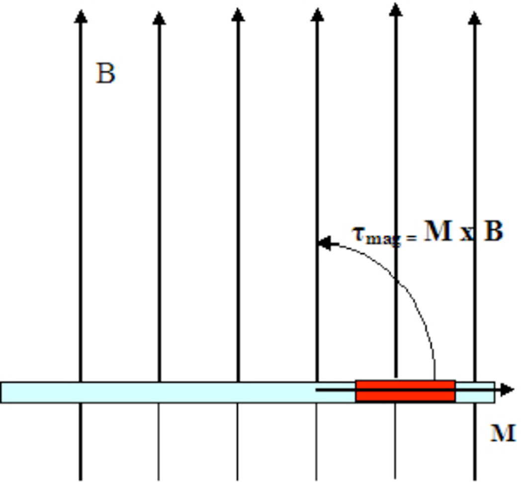
In a constant magnetic field, such as that of an MR scanner, the magnetic moment created in the solenoid experiences a torque, τmag, given by the equation,
| (2) |
or,
| (3) |
where M is the magnetic moment vector, B is the main magnetic field vector, M and B are the respective magnitudes, γ is the initial angle between M and B, and θ is the angle through which the catheter tip is deflected. Note that γ−θ is the final angle between M and B. As a result, the magnetic torque pulls the distal catheter tip into alignment or anti-alignment (depending on the polarity of the current) with the main magnetic field (until θ = γ), in a similar fashion to the way a compass needle behaves in the earth’s gravitational field (Figure 2).
Figure 2.
Catheter positioned in a magnetic field, B. When current is applied, the rotational movement (curved arrow) caused by magnetic torque generated is shown. This magnetic torque is the cross-product of the magnetic moment, M, and the magnetic field, B (large arrows). By definition (right-hand rule), the actual direction of the torque is out of the page, perpendicular to M and B.
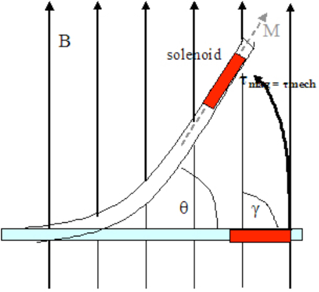
The deflection of the catheter tip, however, is opposed by the stiffness of the catheter and its movement resembles more that of a mechanical spring/cantilever than that of a compass needle. As a result, the magnetic torque τmag will cause the catheter to deflect until it is balanced by the mechanical restoring torque of the catheter, τmech, where
| (4) |
where kθ is related to the elastic modulus of the catheter, and θ is the deflection angle. Note that the term kθ may also depends on θ. This means that stronger force is required to bend the catheter the more it is deflected from its original position. At equilibrium, when τmag = τmech, an equilibrium catheter deflection angle is attained.
By equating (3) and (4), the equilibrium catheter deflection angle, θ, can be calculated:
| (5) |
Substituting for M,
| (6) |
which can be easily rearranged to obtain a linear equation to simplify data fitting.
| (7) |
To simplify discussion and data fitting, distinction in this study is made between the equilibrium catheter deflection angle, θ, and the angular mechanical deflection, θ/sin(γ−θ).
This study seeks to further investigate this novel mechanism by experimental validation of the equation (7) derived above. To this end, each variable is systematically varied while keeping other variables constant. We demonstrate the predicted relationship between the angular mechanical deflection and the physical factors affecting deflection: the number of solenoid turns, applied current, catheter stiffness, and the magnetic field of the MR scanner.
MATERIALS AND METHODS
Device construction
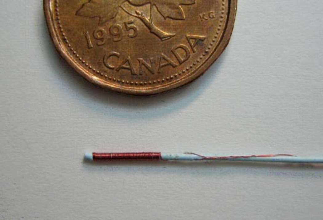
1.8 F (see Table 1) Baltacci catheters (BALT, Montmorency, France) were obtained and the most distal part of the catheter tips containing heavy metal markers were cut off to eliminate confounding magnetic forces and MR artifact. Solenoid coils of 50, 100, 150 turns of 44 AWG magnet wire (California Fine Wire, Grover Beach, CA) were wound on the tips of modified catheters to make three 1.8 F catheters with solenoids of systematically-varied turn number (n) (Figure 3). The final diameter of the wound tips was 0.7 mm and the length of the solenoid coils were 3.2, 6.5 mm, and 10 mm, for the 50, 100, and 150 turn coil catheters, respectively. In addition, a 100 turn solenoid of the same wire was wound on the distal tip of a stiffer 5 F angioplasty catheter (Pursuit, Cook Inc, Bloomington, IN). The 5 F catheter was also modified by removing the angioplasty balloon tip (distal 5 cm). Its final tip diameter was 2.5 mm. and the length of the coil was 3 cm. Loose wire ends were wrapped around the catheter along its length. Local field inhomogeneity artifact from the wire was minimized by braiding of the wire ends along the length of the catheter.
Table 1.
Catheter diameter (outer) conversion table: French to metric.
| French | Millimeters |
|---|---|
| 1 | 0.33 |
| 1.8 | 0.6 |
| 2 | 0.66 |
| 3 | 0.99 |
| 4 | 1.32 |
| 5 | 1.65 |
Figure 3.
Catheter positions in a magnetic field. The torques generated are shown, in relation to the angular mechanical deflection θ, the main magnetic field, B, the induced solenoidal magnetization, M, and the original angle between the catheter and main magnetic field, γ.
Experimental setup
In device testing, the long axis of the solenoid on the distal catheter tips was suspended perpendicular to the MR scanner main magnetic field in a 2 L glass beaker filled with water. The catheter-beaker setup was placed within an 8 channel head imaging coil. Currents in the ±300 mA range were applied remotely using a DC power supply continuous with the solenoid wire in the MRI control room.
Imaging
The sagittal plane containing the catheter tip was identified by an initial 3-plane localizer pulse sequence. Images were obtained using pre-optimized “real-time” MR pulse sequences32 on a 1.5T SIGNA Twinspeed Excite MR scanner (GE Healthcare, Wakesha, WI) using FIESTA (Fast Imaging Employing Steady-state Acquisition) with TR = 2.9 ms, TE = 1.0 ms, flip angle = 50°, 128 × 128 matrix, 5 mm slice thickness, 8-channel head coil. For 3 T imaging, a Signa Excite HD 3T MR scanner (GE Healthcare, Wakesha, WI) was used with a ssFSE (single shot fast spin echo) sequence, TR = 748.7, TE = 30.6, flip angle = 90°, 256 × 128 matrix, 10 mm slice thickness, and a similar 8-channel head coil.
Measurement of deflection angles
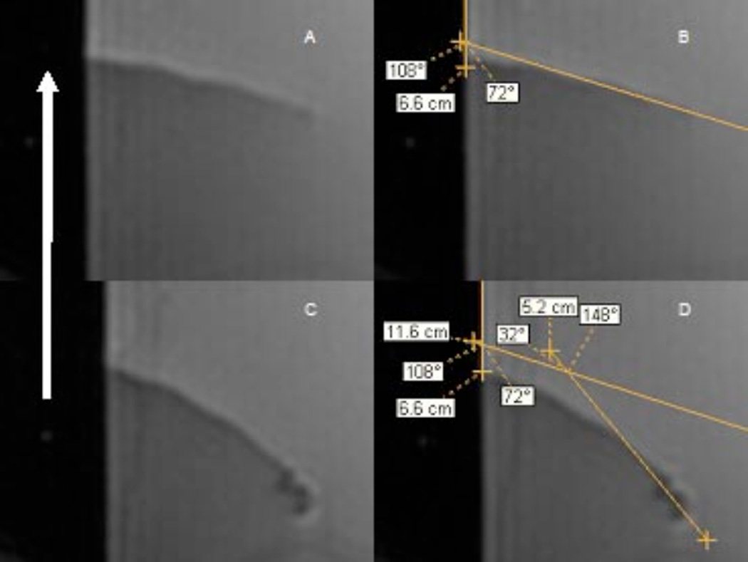
Deflection angles were measured on acquired sagittal DICOM images using eFilm version 1.9.3 (Merge, Milwaukee, WI, USA). The angle γ was measured as the initial angle (before current was applied) between the long axis of the catheter tip and a line drawn at water-air interface (which was parallel to the MR scanner main magnetic field, at all times) (Figure 4A and B). The catheter deflection angle, θ, was measured as the difference between the catheter’s original position before current was applied, and its final equilibrium position after current application (Figure 4C and D). This method was repeated for each number of solenoid turns, catheter type, or magnetic field strength. By definition, at θ = 90 degrees, the catheter tip was in parallel alignment with the MR scanner main magnetic field, B.
Figure 4.
1.8 F catheter with a 100 turn magnet wire solenoid wound at its catheter tip. A penny shown for scale.
RESULTS
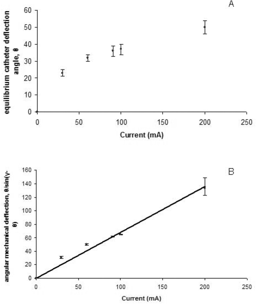
To validate the derived equation (7), each independent variable was varied systematically while holding others constant. The first independent variable tested was the applied current, I. A 1.8 F catheter with 100 turns was placed in the 1.5 T main magnetic field and current was varied using a DC power supply. Images for a 1.8 F catheter with 100 turns (Figure 5) showed that the equilibrium catheter deflection angle, θ, the angular mechanical deflection angle, θ/sin(γ−θ), and local field inhomogeneity artifact increased with increasing current (Figure 5A, C, D and Figure 6). The catheter experienced negligible magnetic torque in the absence of current. As predicted by the derived equation, the increase in the angular mechanical deflection was linear with increasing current in the range of applied currents tested. In fact, significant catheter tip deflections of up to 90 degrees were obtained with applied currents up to 300 mA for the 1.8 F catheter with a 100 turn solenoid at 1.5 T. Direction of deflection was reversed with reversal of current polarity (Fig 5B and C). Although not a primary goal of the study, the catheter and solenoid device was found to be able to tolerate currents as high as 1 A for over 1 minute, without melting the wire insulation and causing an electrical short-circuit. The linear relationship between angular mechanical deflection and current predicted by equation (7) is shown in Figure 7B. The relationship described by equation (7) also held for reversed polarity and for the 5 F catheter (data not shown).
Figure 5.
Measurement of deflection angles. A. 0 mA applied B. same as (A) but with angle measurements. The MR scanner magnetic field, B, is in the sagittal plane (therefore, co-planar with the images), parallel with the meniscus of the water, and points towards the top of the page (white arrow). The initial angle between the catheter tip and B, defined in this study as γ, was measured as 108 degrees. C. 60 mA applied. Note the movement of the catheter from its original position as well as the magnetic susceptibility artifact induced by the solenoid at the catheter tip. D. The deflection angle, θ, is measured as the change in the position of the catheter relative to its original position in A and B. All images show a 1.8 F BALT catheter with a 100 turn solenoid. Imaging done using FIESTA with TR = 2.9 ms, TE = 1.0 ms, flip angle = 50°, 128 × 128 matrix, 5 mm slice thickness, 8-channel head coil.
Figure 6.
MR Images of 1.8 F Catheter with a 100 turn solenoid (FIESTA) A. no current applied. B. −60 mA applied. Note catheter deflection from baseline in A, and local inhomogeneity artifact caused by induced magnetic moment. C. 60 mA (reversed polarity). D. 200 mA (reversed polarity). Note the larger deflection and larger local field inhomogeneity artifact. All images show a 1.8 F BALT catheter with a 100 turn solenoid. Imaging done using FIESTA with TR = 2.9 ms, TE = 1.0 ms, flip angle = 50°, 128 × 128 matrix, 5 mm slice thickness, 8-channel head coil.
Figure 7.
A. Plot of the equilibrium catheter deflection angle, θ, as a function of current for a 1.8 F Baltacci catheter with a 100 turn solenoid at 1.5 T. B. Plot of the angular mechanical deflection as a function of current for a 1.8 F Baltacci catheter with a 100 turn solenoid at 1.5 T (R2 = 0.98).
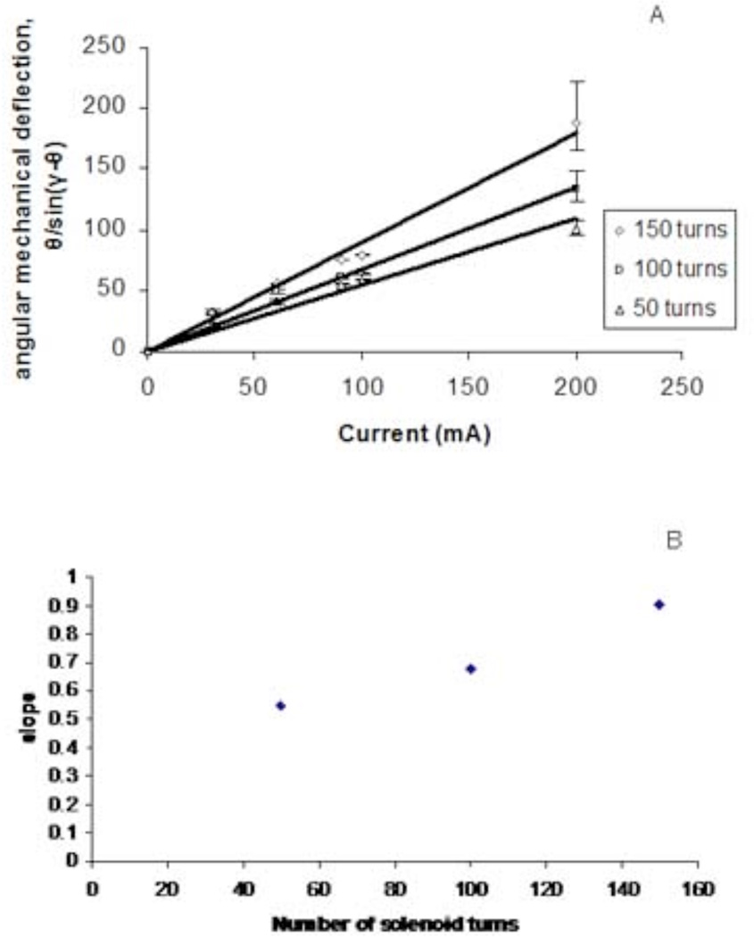
The linear relationship predicted between the angular mechanical deflection, θ/sin(γ−θ), and the number of turns in the solenoid, n, was also observed (Figure 7, R2 = 0.9342). For a 1.8 F catheter, with 60 mA applied, deflection angle, θ, was 31.5, 36, and 45.5 degrees from baseline for 50, 100, and 150 turns, respectively (Figure 7A).
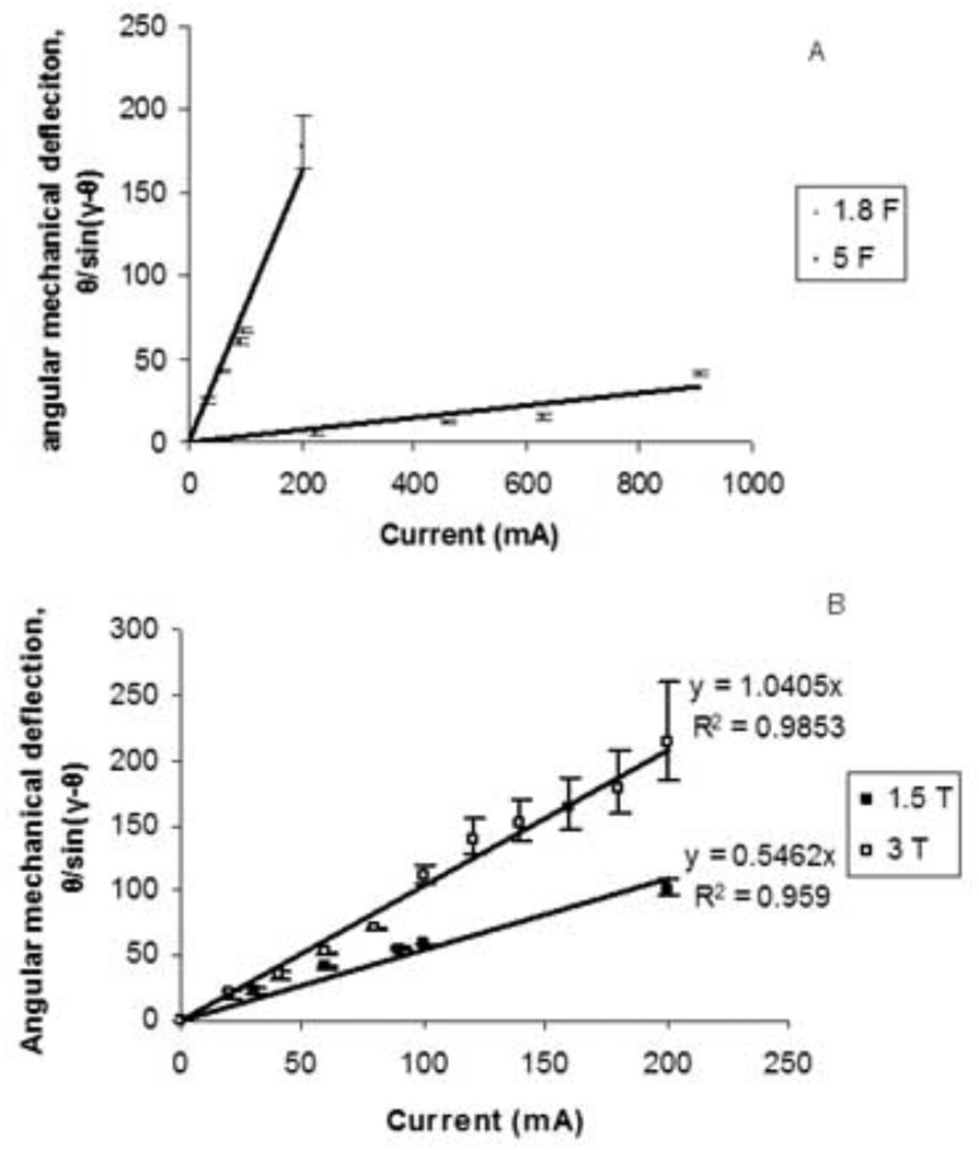
In contrast to the more flexible 1.8 F catheters, higher currents were necessary to achieve significant deflection of the 5 F percutaneous transluminal angioplasty catheters. The 5 F catheter was much stiffer than the 1.8 F catheter (Figure 8). With 800 mA applied to a solenoid of 100 turns on the tip of the 5 F catheter, only 20 degrees of deflection was observed. As predicted, an inverse relationship between catheter elastic property, kθ, and the angular mechanical deflection was observed.
Figure 8.
A. Plot of angular mechanical deflection as a function of current for a 1.8 F Baltacci catheters with solenoids of 50, 100, and 150 turns (R2 = 0.959–0.988). C. Plot of angular mechanical deflection as a function of number of solenoid turns for 1.8 F Baltacci catheters at 1.5 T (R2 = 0.935).
Finally, the magnetic field strength was also systematically varied by carrying out experiments in both a 1.5 T MR scanner and a 3 T MR scanner. While keeping other factors constant, the doubling in field strength resulted in a doubling of the angular mechanical deflection over a wide range of current values, as predicted by the derived equation (7) (Figure 8B).
DISCUSSION
The aim of the present study was to develop and validate an equation for predicting catheter deflection angles for MARC steering of endovascular catheters. We examined the relationship between angular mechanical deflection and a variety of factors affecting MARC steering of endovascular catheters: number of solenoid turns wound around the catheter tip, the applied current, magnetic field strength, and catheter elastic modulus. Our findings indicate that, as predicted by our derived equation (7), angular mechanical deflection at equilibrium, θ/sin(γ−θ), varies linearly with the number of solenoid turns, the applied current, and the magnetic field strength, as well as inversely with catheter stiffness.
Note that the stiffness of the catheter was expected to increase with increasing catheter deflection angles, causing higher currents to be necessary to deflect the catheter tip at deflection angles closer to 90 degrees. According to the results of these experiments, however, kθ remained unchanged, behaving essentially as a constant. Thus, kθ could be rewritten as k, and the effect of changes in deflection angle on the catheter stiffness could be ignored for this particular catheter and setup.
Successful implementation of a catheter device based on this mechanism is dependent on fundamental understanding of the physical factors affecting tip deflection. Subsequent to optimal visualization on the MR image of the catheter tip, the ability to gain fine control of catheter tip deflection under a variety of conditions is essential for proper guidance and prevention of complications. The relationships predicted by the derived equation provide a framework for accurate modeling of the behavior of the specialized catheter tip under a variety of conditions. Accurate understanding of physical factors affecting catheter deflection using this model will potentially allow improved analysis of other issues related to application of this technology, such as image artifact and heating31, which were not primary objectives of this study.
Visualization of the position and orientation of an endovascular catheter tip is essential for its proper guidance and prevention of complications. Heavy-metal compound markers at the catheter tip are typically used for tip visualization in X-ray fluoroscopy. In MRI, however, such markers may either disrupt the image, or, in the case of markers with ferromagnetic properties, be unsafe. Therefore, alternative visualization methods such as passive and active catheter tip tracking are being developed33–35. The specialized catheter studied here takes advantage of the magnetic moment induced in the solenoid at the catheter tip. In addition to experiencing a magnetic torque from the main MR scanner field, the magnetic moment causes local magnetic field inhomogeneity. As a result, in the area of the induced magnetic moment, signal from nearby water proton spins is rapidly lost, resulting in a signal void (often termed a magnetic susceptibility “artifact”) on the MR image. This effect functions beneficially as a catheter tip tracking mechanism, since the catheter tip is located in the area of the signal void. If the effect is too large, however, the image can be severely distorted by the local magnetic inhomogeneity artifact. One approach used to mitigate this effect has been to use an MR imaging pulse sequence that is relatively less sensitive to local magnetic inhomogeneities (such as the ssFSE approach used in the 3T studies reported here). A general approach involves using the derived equation to minimize the applied current and resulting magnetic moment for a given deflection (for example by increasing the number of solenoid turns, or in principle, by increasing μr).
Current applied to a wire causes heating through power dissipation. The heat produced can be hazardous to the health of vessel walls and tissue and is of great concern. Power dissipation is proportional to the square of the applied current and to the resistance of the wire or circuit. The model derived here provides a framework for minimizing the current applied and the resulting heat produced. Further work is ongoing to quantify, characterize, and minimize heating effects of this MARC steering family of devices. The model should also facilitate manufacturing of a device with thermal properties designed to dissipate the heat generated.
Although not affecting the generalizability of our results, there are some factors which limited this study that warrant discussion. The relationship between angular mechanical deflection and magnetic field strength was determined using only 3 different field strengths, at 0 T, 1.5 T and 3 T. A fourth field strength would have further improved the characterization of the relationship between angular mechanical deflection and magnetic field strength. Unfortunately, MRI scanners of field strengths other than the ones used, and with “real-time” pulse sequence capabilities, were unavailable at our institution. Nonetheless, the doubling of the angular mechanical deflection with the doubling of magnetic field strength, however, occurred consistently over a wide range of current values, consistent with equation 7.
The data in this study supports the conclusion that the angular mechanical deflection is inversely related to the catheter stiffness. No quantitative estimates of the elastic modulus of the catheters, however, were made. Obtaining pre-manufactured catheters of identical geometry but differing elastic modulus is virtually impossible. A large difference in elastic modulus, or stiffness, between the 1.8 F catheter and the 5 F catheter was noted qualitatively. However, there is also a difference in the cross-sectional area of the catheters, another factor affecting the angular mechanical deflection (equation 7). Indeed, the inverse relationship between angular mechanical deflection and catheter stiffness was readily apparent.
Lastly, the derived equation fits a two-dimensional model for catheter tip deflection. Using a single solenoid at the catheter tip, two possible deflection movements for the catheter tip exist: alignment with the main magnetic field or anti-alignment with the main magnetic field. This movement is similar to a pendulum swing and results in deflections within a two-dimensional plane. For three-dimensional deflections, magnetic moments in three-dimensional space are necessary. This can be achieved by inducing orthogonal magnetic moments in paired Helmholtz coils at the catheter tip, in addition to the solenoid coil. The resultant three-dimensional magnetic moment vector (composed of the combination of individual magnetic moments in the Cartesian axes) would experience three-dimensional torque, and result in three-dimensional catheter tip deflections. This was demonstrated by Roberts et al.31 and the derived equation can be readily generalized to three-dimensions.
In summary, we have derived and experimentally validated an equation for magnetically-assisted remote control steering of endovascular catheters. The equation provides a framework for accurate modeling of the behavior of the specialized catheter tip. Such understanding is pivotal to the application of this novel mechanism in MR-guided endovascular intervention.
Figure 9.
A. Plot of angular mechanical deflection as a function of current for a 1.8 F Baltacci catheter with a solenoid of 100 turns and a 5 F PCTA catheter with a solenoid of 100 turns at 1.5 T. B. Plot of angular mechanical deflection as a function of current for a 1.8 F Baltacci catheter with a solenoid of 50 turns at 1.5 T and 3 T.
Acknowledgements
Canadian Institutes of Health Research, Ontario Research and Development Challenge Fund, Jeff Siewerdsen, David Mikulis, Ryan Schreier, Dr. Karel TerBrugge and Yoca TerBrugge of Yocan Medical Systems and BALT®, Mark Mariecki at Cook®, Igor Sitartchouk, and Mark Gertner.
Footnotes
Parts of this work were presented at the 2005 Annual Meeting of the AAPM, for which Dr Settecase was awarded the Young Investigator Award.
REFERENCES
- 1.Endovascular versus surgical treatment in patients with carotid stenosis in the Carotid and Vertebral Artery Transluminal Angioplasty Study (CAVATAS): a randomised trial. Lancet. 2001;357:1729–1737. [PubMed] [Google Scholar]
- 2.Razavi MK, Hwang G, Jahed A, et al. Abdominal myomectomy versus uterine fibroid embolization in the treatment of symptomatic uterine leiomyomas. AJR Am J Roentgenol. 2003;180:1571–1575. doi: 10.2214/ajr.180.6.1801571. [DOI] [PubMed] [Google Scholar]
- 3.Molyneux AJ, Kerr RS, Yu LM, et al. International subarachnoid aneurysm trial (ISAT) of neurosurgical clipping versus endovascular coiling in 2143 patients with ruptured intracranial aneurysms: a randomised comparison of effects on survival, dependency, seizures, rebleeding, subgroups, and aneurysm occlusion. Lancet. 2005;366:809–817. doi: 10.1016/S0140-6736(05)67214-5. [DOI] [PubMed] [Google Scholar]
- 4.Hoffman SN, TenBrook JA, Wolf MP, et al. A meta-analysis of randomized controlled trials comparing coronary artery bypass graft with percutaneous transluminal coronary angioplasty: one- to eight-year outcomes. J Am Coll Cardiol. 2003;41:1293–1304. doi: 10.1016/s0735-1097(03)00157-8. [DOI] [PubMed] [Google Scholar]
- 5.Becker DM, Philbrick JT, Selby JB. Inferior vena cava filters. Indications, safety, effectiveness. Arch Intern Med. 1992;152:1985–1994. [PubMed] [Google Scholar]
- 6.Qureshi AI. Endovascular treatment of cerebrovascular diseases and intracranial neoplasms. Lancet. 2004;363:804–813. doi: 10.1016/S0140-6736(04)15697-3. [DOI] [PubMed] [Google Scholar]
- 7.Morris P. Interventional neuroradiology in the treatment of brain tumors. Neuroimaging Clin N Am. 1999;9:767–778. [PubMed] [Google Scholar]
- 8.Rossle M, Siegerstetter V, Huber M, et al. The first decade of the transjugular intrahepatic portosystemic shunt (TIPS): state of the art. Liver. 1998;18:73–89. doi: 10.1111/j.1600-0676.1998.tb00132.x. [DOI] [PubMed] [Google Scholar]
- 9.Seldinger SI. Catheter replacement of the needle in percutaneous arteriography; a new technique. Acta Radiol. 1953;39:368–376. doi: 10.3109/00016925309136722. [DOI] [PubMed] [Google Scholar]
- 10.McDougall CG, Halbach VV, Dowd CF, et al. Causes and management of aneurysmal hemorrhage occurring during embolization with Guglielmi detachable coils. J Neurosurg. 1998;89:87–92. doi: 10.3171/jns.1998.89.1.0087. [DOI] [PubMed] [Google Scholar]
- 11.Vinuela F, Duckwiler G, Mawad M. Guglielmi detachable coil embolization of acute intracranial aneurysm: perioperative anatomical and clinical outcome in 403 patients. J Neurosurg. 1997;86:475–482. doi: 10.3171/jns.1997.86.3.0475. [DOI] [PubMed] [Google Scholar]
- 12.Ross IB, Dhillon GS. Complications of endovascular treatment of cerebral aneurysms. Surg Neurol. 2005;64:12–18. doi: 10.1016/j.surneu.2004.09.045. discussion 18–19. [DOI] [PubMed] [Google Scholar]
- 13.Fasseas P, Orford JL, Panetta CJ, et al. Incidence, correlates, management, and clinical outcome of coronary perforation: analysis of 16,298 procedures. Am Heart J. 2004;147:140–145. doi: 10.1016/s0002-8703(03)00505-2. [DOI] [PubMed] [Google Scholar]
- 14.Fukutomi T, Suzuki T, Popma JJ, et al. Early and late clinical outcomes following coronary perforation in patients undergoing percutaneous coronary intervention. Circ J. 2002;66:349–356. doi: 10.1253/circj.66.349. [DOI] [PubMed] [Google Scholar]
- 15.Gruberg L, Pinnow E, Flood R, et al. Incidence, management, and outcome of coronary artery perforation during percutaneous coronary intervention. Am J Cardiol. 2000;86:680–682. A688. doi: 10.1016/s0002-9149(00)01053-5. [DOI] [PubMed] [Google Scholar]
- 16.Gunning MG, Williams IL, Jewitt DE, et al. Coronary artery perforation during percutaneous intervention: incidence and outcome. Heart. 2002;88:495–498. doi: 10.1136/heart.88.5.495. [DOI] [PMC free article] [PubMed] [Google Scholar]
- 17.Gradinscak DJ, Young N, Jones Y, et al. Risks of outpatient angiography and interventional procedures: a prospective study. AJR Am J Roentgenol. 2004;183:377–381. doi: 10.2214/ajr.183.2.1830377. [DOI] [PubMed] [Google Scholar]
- 18.Young N, Chi KK, Ajaka J, et al. Complications with outpatient angiography and interventional procedures. Cardiovasc Intervent Radiol. 2002;25:123–126. doi: 10.1007/s00270-001-0105-8. [DOI] [PubMed] [Google Scholar]
- 19.Balduf LM, Langsfeld M, Marek JM, et al. Complication rates of diagnostic angiography performed by vascular surgeons. Vasc Endovascular Surg. 2002;36:439–445. doi: 10.1177/153857440203600604. [DOI] [PubMed] [Google Scholar]
- 20.Willinsky RA, Taylor SM, TerBrugge K, et al. Neurologic complications of cerebral angiography: prospective analysis of 2,899 procedures and review of the literature. Radiology. 2003;227:522–528. doi: 10.1148/radiol.2272012071. [DOI] [PubMed] [Google Scholar]
- 21.Lin PH, Bush RL, Peden EK, et al. Carotid artery stenting with neuroprotection: assessing the learning curve and treatment outcome. Am J Surg. 2005;190:850–857. doi: 10.1016/j.amjsurg.2005.08.008. [DOI] [PubMed] [Google Scholar]
- 22.Dick AJ, Guttman MA, Raman VK, et al. Magnetic resonance fluoroscopy allows targeted delivery of mesenchymal stem cells to infarct borders in Swine. Circulation. 2003;108:2899–2904. doi: 10.1161/01.CIR.0000095790.28368.F9. [DOI] [PMC free article] [PubMed] [Google Scholar]
- 23.Henk CB, Higgins CB, Saeed M. Endovascular interventional MRI. J Magn Reson Imaging. 2005;22:451–460. doi: 10.1002/jmri.20411. [DOI] [PubMed] [Google Scholar]
- 24.Hong SJ, Wong JT, Bloch KJ. Reactions to radiocontrast media. Allergy Asthma Proc. 2002;23:347–351. [PubMed] [Google Scholar]
- 25.Meade TJ, Taylor AK, Bull SR. New magnetic resonance contrast agents as biochemical reporters. Curr Opin Neurobiol. 2003;13:597–602. doi: 10.1016/j.conb.2003.09.009. [DOI] [PubMed] [Google Scholar]
- 26.Louie AY, Huber MM, Ahrens ET, et al. In vivo visualization of gene expression using magnetic resonance imaging. Nat Biotechnol. 2000;18:321–325. doi: 10.1038/73780. [DOI] [PubMed] [Google Scholar]
- 27.Li WH, Parigi G, Fragai M, et al. Mechanistic studies of a calcium-dependent MRI contrast agent. Inorganic Chemistry. 2002;41:4018–4024. doi: 10.1021/ic0200390. [DOI] [PubMed] [Google Scholar]
- 28.Li WH, Fraser SE, Meade TJ. A calcium-sensitive magnetic resonance imaging contrast agent. Journal Of The American Chemical Society. 1999;121:1413–1414. [Google Scholar]
- 29.Lowe MP, Parker D, Reany O, et al. pH-dependent modulation of relaxivity and luminescence in macrocyclic gadolinium and europium complexes based on reversible intramolecular sulfonamide ligation. Journal Of The American Chemical Society. 2001;123:7601–7609. doi: 10.1021/ja0103647. [DOI] [PubMed] [Google Scholar]
- 30.Josephson L, Perez JM, Weissleder R. Magnetic nanosensors for the detection of oligonucleotide sequences. Angewandte Chemie-International Edition. 2001;40:3204. doi: 10.1002/1521-3773(20010903)40:17<3204::AID-ANIE3204>3.0.CO;2-H. -+ [DOI] [PubMed] [Google Scholar]
- 31.Roberts TP, Hassenzahl WV, Hetts SW, et al. Remote control of catheter tip deflection: an opportunity for interventional MRI. Magn Reson Med. 2002;48:1091–1095. doi: 10.1002/mrm.10325. [DOI] [PubMed] [Google Scholar]
- 32.Settecase F, Sussman MS, Roberts TPL. Factors affecting remote control catheter steering in interventional MRI: pulse sequence optimization and an equation for predicting deflection. Medical Physics. 2005;32:1889. [Google Scholar]
- 33.Hillenbrand CM, Elgort DR, Wong EY, et al. Active device tracking and high-resolution intravascular MRI using a novel catheter-based, opposed-solenoid phased array coil. Magn Reson Med. 2004;51:668–675. doi: 10.1002/mrm.20050. [DOI] [PubMed] [Google Scholar]
- 34.Zuehlsdorff S, Umathum R, Volz S, et al. MR coil design for simultaneous tip tracking and curvature delineation of a catheter. Magn Reson Med. 2004;52:214–218. doi: 10.1002/mrm.20108. [DOI] [PubMed] [Google Scholar]
- 35.Miquel ME, Hegde S, Muthurangu V, et al. Visualization and tracking of an inflatable balloon catheter using SSFP in a flow phantom and in the heart and great vessels of patients. Magn Reson Med. 2004;51:988–995. doi: 10.1002/mrm.20041. [DOI] [PubMed] [Google Scholar]


