Abstract
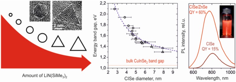
We report a simple, high-yield colloidal synthesis of copper indium selenide nanocrystals (CISe NCs) based on a silylamide-promoted approach. The silylamide anions increase the nucleation rate, which results in small-sized NCs exhibiting high luminescence and constant NC stoichiometry and crystal structure regardless of the NC size and shape. In particular, by systematically varying synthesis time and temperature, we show that the size of the CISe NCs can be precisely controlled to be between 2.7 and 7.9 nm with size distributions down to 9–10%. By introducing a specific concentration of silylamide-anions in the reaction mixture, the shape of CISe NCs can be preselected to be either spherical or tetrahedral. Optical properties of these CISe NCs span from the visible to near-infrared region with peak luminescence wavelengths of 700 to 1200 nm. The luminescence efficiency improves from 10 to 15% to record values of 50–60% by overcoating as-prepared CISe NCs with ZnSe or ZnS shells, highlighting their potential for applications such as biolabeling and solid state lighting.
Keywords: copper indium selenide, CISe nanocrystals, size and shape control, quantum dot colloids, luminescence, lighting applications
Introduction
Colloidal NCs from the I–III–VI group semiconductors have attracted much attention during the past years as promising alternatives for “classical” lead and cadmium chalcogenide NCs.1,2 Work on I–III–VI materials is motivated by their reduced toxicity as well as by their successful applications in thin film photovoltaics.3,4 Furthermore, semiconducting I–III–VI quantum dots are considered for lighting applications5 and for bioimaging,6 due to their strong emission in the visible and near-infrared spectral region. Copper indium selenide (CISe) is one of the most promising among I–III–VI materials, owing to its narrow band gap (1.04 eV, direct), relatively large exciton Bohr radius (10.6 nm), and high absorption coefficient (∼105 cm–1).1,7
While considerable work exists on copper indium sulfide (CIS) synthesis methods, approaches for CISe NCs are less developed.1 Since the first stable colloids of CISe NCs were achieved,8 relatively large NC sizes (>6 nm) have been almost exclusively considered.9−14 Efforts have targeted control of the morphology (e.g., spheres,9,12 tetrahedrons,10 hexagonal plates,11,12 octahedrons,15 or wires16), composition,9,13,14 and crystal structure1,12 of CISe-based NCs as well as achieving good monodispersity.
However, for applications where strong and stable luminescence is important,6,17 small NC size is desirable because the luminescence quantum yield (QY) decreases as the size of NC increases.18−20 Small CISe NCs with photoluminescence QYs up to 25% were first reported by Allen et al.21 Nose et al.22 prepared several sizes of nearly stoichiometric CuInSe2 NCs with PLQYs up to 5%, later improving this luminescence to 16% by coating the CISe NCs with a ZnSe shell.23 Recently, several groups observed significant improvement of PL efficiency with the addition of a thin ZnS shell around CISe NC cores.7,24,25 Cassette et al.24 observed PLQYs of 10–50% depending on the size of CISe-cores while Zhong et al.7 prepared CISe/ZnS NCs with PLQYs up to 26%. Park et al.25 synthesized In-rich Cu–In–Se NCs, which have a PL efficiency of 20–30% before and record PLQYs of 40–60% after ZnS-shell protection. This recipe, however, was shown for only one size of CISe NCs.
This survey of literature highlights the importance of composition on the resulting luminescence. Among the reported luminescent CISe NCs, several are in fact highly S-doped (i.e., quaternary CISSe NCs)7,24 because of the use of long chain thiols in the synthetic approach introduced to balance Cu-reactivity.7 Among pure (i.e., S-free) CISe NCs, the highest PLQYs were reported for In-rich CISe phases,21,25 while stoichiometric copper indium diselenide (CuInSe2) NCs have moderate PL properties.22,23 This can be attributed to the donor–acceptor pair (DAP) luminescence mechanism for I–III–VI NCs, which has been explained for CIS NCs.2 For In-rich CIS NCs, the PL efficiency is proportional to the number of donor–acceptor defects, while Cu-rich CIS NCs are found to be nonemissive.2 The optimal compositions for CIS NCs for PL efficiency have Cu-to-In ratios between 0.4 and 0.8.2
In this paper we report a simple, high-yield synthesis of CISe NCs with precise size control and programmable shape (spherical or tetrahedral). The synthesis yields small NCs with consistent stoichiometry and crystal structure that exhibit bright and stable luminescence, reaching highly competitive PLQY values of 50 and 60% after the ZnS and ZnSe coatings, respectively.
This preparation of sub-10 nm CISe NCs is achieved using a silylamide-promoted synthetic approach.20 Silylamide salt (here, lithium bis(trimethylsilyl)amide, LiN(SiMe3)2) is coinjected together with anion-precursor into the solution, containing cation-ions. In the presence of silylamide salt, the NC nucleation occurs at a higher rate, which can be explained by the formation of highly reactive metal-silylamide intermediates, followed by their decomposition and fast reaction with chalcogen precursor.20 We demonstrate that this leads to small-sized NCs with stable composition and crystal structure. While this strategy was successfully applied to make high-quality PbSe and Ag2Se NCs,18,20 this work presents the first use of silylamide-promoted synthesis to achieve high performance ternary compounds.
Experimental Section
Materials
Indium(III) chloride (anhydrous, 99.999%), selenium (99.99%), and tri-n-octylphosphine (TOP, 97%) were purchased from Strem; copper(I) chloride (anhydrous, ≥99.99%), diethylzinc (1 M in hexane), sulfur (99.5%), oleic acid (techn. 90%), toluene (99.7%), ethanol (99.9%), and methanol (99.9%) from Sigma Aldrich; lithium bis(trimethylsilyl)amide (LiN(SiMe3)2, 95%) and oleylamine (80–90%) from Acros.
General Remarks
All syntheses were conducted using a standard Schlenk line technique. Precursors and their stock solutions were prepared and stored under inert atmosphere. Elemental stock solutions of In (0.5 M InCl3 in TOP), Cu (0.5 M CuCl in TOP) and Se (1.0 M Se in TOP) were prepared by dissolving the elements in TOP at room temperature. To prepare a homogeneous stock solution of LiN(SiMe3)2, 4.2 g LiN(SiMe3)2 were dissolved in 10 mL TOP, and the mixture was sonicated for 15 min. For better temperature control, a nitrate salt bath (KNO3/NaNO3 = 1:1) was used instead of a standard heating mantle.
Synthesis of Spherical CISe Nanocrystals
In a typical synthesis of 4.2 nm spherical CISe nanocrystals, 0.5 mL of CuCl stock solution (0.25 mmol of Cu) was mixed with 0.5 mL of InCl3 stock solution (0.25 mmol of In) and diluted with 6 mL TOP. This mixture was then transferred to the Schlenk line and additionally purified for 30 min at 100 °C. Afterward, the reaction flask was backfilled with N2 and heated to 285 °C using a nitrate salt bath. At 285 °C, a mixture containing 1 mL of Se stock solution (1 mmol of Se) and 1 mL of LiN(SiMe3)2 stock solution was swiftly injected in the reaction flask. The formation of CISe NCs was indicated by gradual color change of the solution to red, brown, and finally deep-brown. The reaction flask was rapidly cooled to room temperature after 3 min of growth time. CISe NCs were purified by a typical solvent/nonsolvent procedure with alternate addition of toluene and ethanol/methanol (3:1) mixture and centrifugation. The obtained CISe NCs form long-term stable colloidal solutions in any nonpolar solvent, for instance toluene or chloroform. The typical yields of CISe nanocrystals are 80–90%.
The mean size of CISe NCs can be precisely controlled from 3 to 5 nm by varying the injection temperature and growth time, as discussed in the text. To prepare CISe NCs with diameters >5 nm, smaller amounts of lithium silylamide and longer growth times are used. Ultrasmall <3 nm CISe NCs can be prepared with very short growth times.
Synthesis of Tetrahedral CISe Nanocrystals
CISe NCs of tetrahedral shape can be synthesized, taking the above-described protocols but with smaller amounts of LiN(SiMe3)2. In a typical experiment of 5.6 nm CISe nanotetrahedrons, 2 mL of CuCl stock solution (1 mmol of Cu) was mixed with 2 mL of InCl3 stock solution (1 mmol of In) and 2 mL TOP. After purification, the reaction flask was heated to 320 °C. At 320 °C, a mixture of 4 mL TOPSe (4 mmol of Se) and 2 mL of LiN(SiMe3)2 stock solutions was swiftly injected in the reaction flask. The reaction flask was rapidly cooled to the room temperature after 1 min of growth time. Tetrahedral CISe NCs were purified as described above. The size of the tetrahedral CISe NCs can be altered by growth time and the amount of lithium silylamide.
ZnS and ZnSe Shells Around CISe Nanocrystals
The Zn chalcogenide shells were prepared as for CdSe NCs.26 Briefly, 5 mL of TOP and 1 mL of TOPSe (TOPS) 1 M were added to as-prepared CISe NCs (∼5 mg/mL in toluene). The solution was evacuated for 30 min under vacuum, backfilled with N2, and heated to 150 °C. At 150 °C, the mixture of ZnEt2 (0.5 mmol) and TOPSe (TOPS) (0.5 mmol) in 5 mL TOP was added drop by drop during 15 min. Directly after addition of Zn/Se injection mixture, the reaction mixture was quenched with the water bath and purified by sequential addition of toluene and ethanol and centrifugation. Precipitate was dissolved in toluene and 0.5 mL of oleic acid was added, resulting in a stable solution. The toluene/ethanol purification was repeated another 2 times. Obtained CISe/ZnSe or CISe/ZnS NCs form stable colloidal solutions for months, when stored at room temperature in the glovebox.
Characterization of CISe Nanocrystals
Transmission electron microscope (TEM) images were taken with a Philips CM12 electron microscope operating at 100 kV; high-resolution TEM images were acquired at JEOL 2010 at 200 kV and Technai F30 at 300 kV. EDX analysis was performed at FEI Quanta 200 FEG. Size distributions were taken using ImageJ software. Absorption measurements were carried out with a Cary 5E UV–vis-near-infrared spectrophotometer. Photoluminescence spectra were taken by exciting the NCs in solution with a CW 405 nm laser and recording the emission spectrum with an Ocean Optics QD65000 spectrometer. Some near-IR PL spectra were measured with a setup, consisting of chopped argon ion laser (514 nm), an Acton Research Corporation Spectra Pro 150 monochromator, and Judson InSb photodiode. Powder X-ray diffraction was measured by a custom-built rotating anode X-ray diffractometer, by using the Cu Kα line (1.5419 Å) and a Vantec PSD detector. The PLQY measurements were made, following a published procedure27 and using Rhodamine B in ethanol as a reference.28
Results and Disscussion
Optimization of the CISe NC Synthesis
Following the typical recipes for CISe NCs9,12 and previous work on silylamide-promoted synthesis,18,20 we initially try oleylamine-based protocols. While we obtain CISe NCs (Supporting Information Figure S1), no PL is detected. We attribute this to the fact that oleylamine catalyzes NC oxidation, which degrades the PL.7 Furthermore, long chain amines are known to etch NCs, which could also impact the PL.10,12,21 We therefore select tri-n-octylphosphine as a solvent, a selection that is further supported by the observation of Cassette et al. that TOP improves the luminescence properties of CISe NCs.24 In a typical synthesis, we inject a mixture of LiN(SiMe3)2 and Se in TOP in a solution containing CuCl and InCl3 in TOP at elevated temperatures, as shown in the Scheme 1.
Scheme 1. Reaction Pathway Towards Colloidal CISe Nanocrystals.

This synthesis yields small sized of CISe NCs (Figure 1a) with narrow size distributions down to 9–10% (Supporting Information Figure S2). HR-TEM images of single NCs reveal a highly faceted morphology of obtained CISe NCs (Figure 1b,c). The interplanar distance of 0.33 nm corresponds to that between (111) atomic planes in bulk CuInSe2. This orientation and the hexagonal shape observed in the HR-TEM pictures allow us to determine that the obtained CISe NCs exhibit cubooctaherdal morphology. For the sake of simplicity, we refer to these CISe NCs as “spherical” throughout the text.
Figure 1.
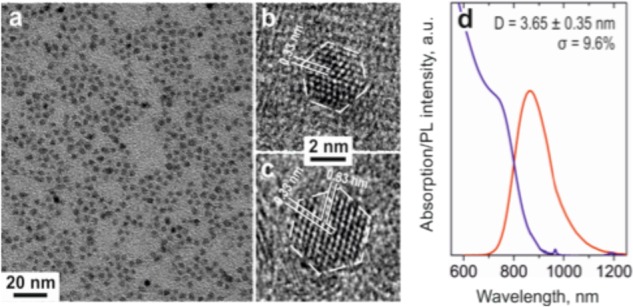
(a) TEM image of monodisperse CISe NCs; (b,c) HR-TEM images of two different sized NCs, showing characteristic (111) interplanar distances of the zinc blende CuInSe2 bulk; (d) optical properties of the monodisperse CISe NCs.
The optical properties of the 3.65 nm CISe NCs are shown in Figure 1d. The absorption spectrum exhibits a first excitonic transition peak at 750 nm, corresponding to a band gap of around 1.7 eV, which is expected for these small NCs. The photoluminescence (PL) spectrum peaks at 900 nm. This Stokes shift of 150 nm is consistent with the DAP luminescence mechanism.1,2
Size Control
By adjusting reaction parameters including growth time, injection temperature, and/or the amount of silylamide, we tune the size of these spherical CISe NCs in the range of 2.7–7.9 nm. For the size range of 3–5 nm, accurate size tuning is possible by regulating growth time and temperature (Figure 2a). With reaction time, CISe NCs gradually increase in size (Supporting Information Figure S3). We note that the formation of CISe NCs occurs within minutes. The impact of growth temperature on the mean size of CISe NCs resulting from a 3 min synthesis is shown in Figure 2b. To obtain spherical CISe NCs larger than 5 nm in diameter, smaller amounts of lithium silylamide and longer times are needed. The smaller silylamide concentrations result in fewer nucleation events and allow for comparatively larger sized nanocrystals. Similar trends were observed for other systems, such as PbSe or Bi NCs.18,29
Figure 2.
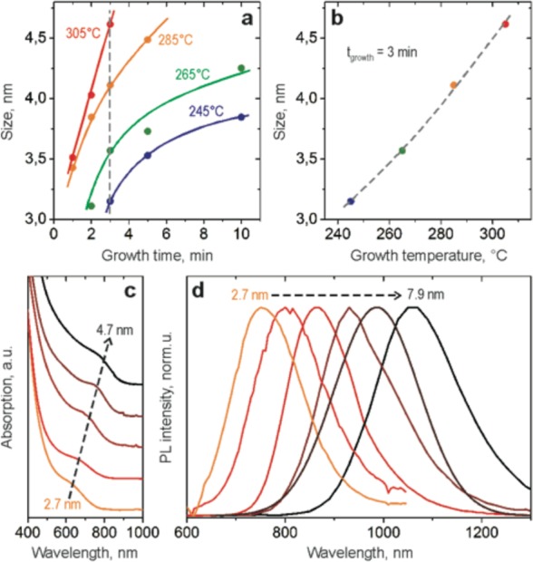
(a) Precise size control of small CISe NCs possible by variation of the growth time and/or growth temperature; (b) plot of CISe NCs size as a function of growth temperature (data corresponds to the dashed line at 3 min growth marking (a)) shows quasi linear behavior. Starting concentrations of CuCl, InCl3, and LiN(SiMe3)2 in (a,b) are 0.02 M, 0.02 M, and 0.2 M, respectively; (c,d) absorbance and photoluminescence of different size spherical CISe NCs.
Size-dependent absorption and PL spectra are shown in Figure 2c,d. The absorption onset shifts from 620 to 800 nm and the PL peak shifts from 750 to 1100 nm when the NCs size increases from 2.7 to 4.7 nm. For bigger NCs, absorption shows a broader shoulder, which we attribute to larger size distributions (Supporting Information Figure S4) and decreasing quantum confinement.
Shape Control
By decreasing the concentration of silylamide anions in the reaction mixture, we increase the average size of CISe NCs; however, the amount of silylamide also plays a decisive role for the morphology of obtained CISe NCs. At a certain threshold concentration of silylamide, CISe NCs become tetrahedral in shape and exhibit excellent shape uniformity (Figure 3a). Assuming a zinc blend crystal structure (which is shown experimentally later in text) and the interplanar (111) distances in Figure 3b, it is possible to visualize such NCs using Diamond graphical software (Figure 3c). We find that all 4 surfaces of tetrahedral CISe NCs are (111). A possible explanation for this shape can be related to the high packing density of atoms on the (111) surface, which enables surfaces to be well saturated even by weakly bonded ligands.30 Another possible explanation could be the difference in affinities of coordinating ligands to different surfaces, a known phenomenon for colloidal NCs.31
Figure 3.
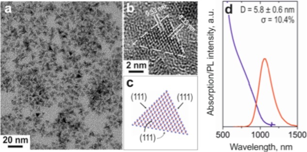
(a) Typical TEM image of tetrahedral CISe NCs; (b,c) HR-TEM picture and atomic reconstruction of single CISe NC with a tetrahedral shape; (d) Representative absorption and PL spectra for tetrahedral CISe NCs.
As with the “spherical” NCs, the tetrahedral CISe NCs exhibit size tunable optical properties. Representative absorption and emission spectra are shown in Figure 3d. In addition to varying the silylamide content, the size of tetrahedral CISe NCs can be tuned by the growth time (Supporting Information Figure S5). The dependency of PL emission and shape on the LiN(SiMe3)2 amount is summarized in Figure 4a.
Figure 4.
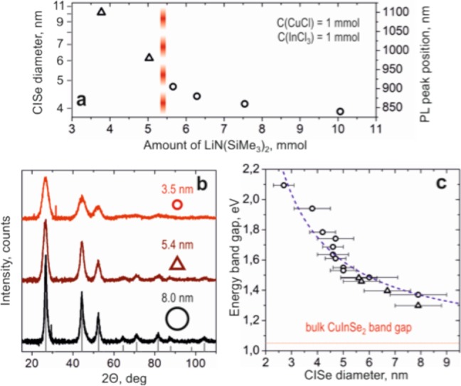
(a) Influence of silylamide amount on shape, size and PL peak emission of CISe NCs; (b) powder XRD patterns for two different sizes of spherical CISe NCs and a tetrahedral NC; reference data for the zinc blende bulk CuInSe2 structure; (c) energy band gap as a function of CISe NCs size; spherical and tetrahedral shapes are represented by open circles and triangles, respectively.
Structure & Compositional Trends
We investigate the crystal structure and composition of the “spherical” and tetragonal NCs of different sizes. Bulk CuInSe2 is reported in three different crystal structures: tetragonal chalcopyrite (CH), cubic zinc blende (ZB) and hexagonal wurtzite (WZ).32 Chalcopyrite polymorph can also be considered a more ordered version of cubic CuInSe2.1,12 The CH and ZB structures are closely related, both having the characteristic 0.33-nm interplanar distance found in the spherical- and tetragonal-shaped NCs (Figures 1b,c and 3b). To identify the crystal structure of our NCs, we perform wide-angle X-ray diffraction (XRD) measurements. Figure 4b presents diffractograms for different sizes and shapes of CISe NCs. Peak broadening is observed for smaller NCs, but all measured NCs show the same cubic zinc blend (δ-CISe) crystal structure (see Supporting Information Figure S6 for fits of diffractograms with known bulk CISe structures).
Energy dispersive X-ray (EDX) spectroscopy (shown in Supporting Information Figure S7 and summarized in Table 1) reveals an off-stoichiometric Cu-to-In ratio that remains consistent for the different shaped and sized NCs, which is in contrast to other reports.15,24 This shows that the composition of CISe NCs is not affected by the growth time, suggesting a well-balanced reactivity of Cu and In cations.24 We find that our CISe NCs are slightly In-rich with a Cu-to-In ratio of about 0.78, consistent with the ratio found for high PL CIS NCs.28
Table 1. Composition of CISe NCs Determined from EDX Spectroscopy.
| morphology | growth time, min | Cu, at% | In, at% | Se, at% |
|---|---|---|---|---|
| Spherical | 2 | 21.21 | 27.63 | 51.16 |
| 10 | 21.83 | 24.94 | 53.23 | |
| Tetrahedral | 1.5 | 20.37 | 28.98 | 50.64 |
| 5 | 21.10 | 27.56 | 51.33 |
In Figure 4c, we report the experimental dependence of the energy band gap on the size of the CISe NCs where the size of CISe NCs is determined from TEM while the band gap is estimated from the position of the first exciton peak in the absorption spectra. For large NCs with very broad absorption features, band gap was estimated considering a Stokes shift of 145 nm from the PL emission peak. The band gap of CISe NCs can be varied from 1.3 to 2.1 eV by decreasing NC size from 8 to 2 nm and the sizing curve, which includes the different shaped NCs can be fit with E ≈ Ebulk + (C × R–2).33 Here C = 8.2 and Ebulk is 1.1 eV. This fit is consistent with an Ebulk of 1.1–1.2 eV expected for indium-rich CISe.34,35 The good fit of the energy bandgap versus NC size data further emphasizes that our synthesis approach results in NCs where the composition is not affected by NC shape or size.
CISe/ZnS and CISe/ZnSe Nanocrystals
The growth of a thin crystalline shell is a widely used method to protect semiconducting NCs against oxidation and photodegradation. Zn chalcogenides are commonly used shell materials due to their wide band gap. CISe NCs coated with ZnS7,23,24 and ZnSe23 shells have shown improved luminescent efficiencies.
We cover our CISe NCs with both Zn chalcogenide materials (Figure 5) using the approach of Danek et al.26 While uncoated CISe NCs exhibit a QY of ∼15%, a multifold improvement of PL intensity is observed after growth of the chalcogenide shell. A record value for CISe NCs of 60% is achieved in the case of a ZnSe shell. For the case of ZnS shell, a PLQY is slightly smaller (∼50%) but still in the range of the highest reported values for CISe/ZnS core/shell NCs.24,25 In addition, the PL signal is stable and the QYs are retained for at least 3 months.
Figure 5.
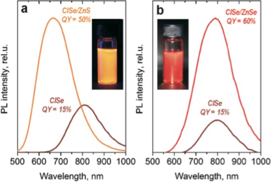
PL spectra of CISe NCs before and after coating with (a) ZnS and (b) ZnSe shells. (Insets) Photographs of CISe/ZnS and CISe/ZnSe colloidal solutions under illumination.
The ZnSe shell may provide higher efficiencies than the ZnS shell since ZnSe has a relatively small, 2% lattice mismatch with CISe,36 while the lattice mismatch for CISe–ZnS is ∼7%.24 A lattice mismatch between core and shell materials can prevent the passivation of surface traps, which hamper the bright PL.37
With shell growth, the average size of NCs increases by ∼0.5 nm (Supporting Information Figure S8). Thus, the shell thickness is estimated to be about 1 monolayer (i.e., half of the lattice parameter). The fact that a blue-shift is observed in the PL for both chalcogenide suggests a partial alloying of CISe core and ZnS(Se) shell materials. Supporting Information Figure S9 shows that Stokes shifts of 120 and 90 nm are found for the ZnSe and ZnS shells, respectively. The fact that the Stokes shifts are both different from that of the bulk is consistent with electronic confinement from the Zn-chalcogenide shells influencing the band edge (determining absorption) and the donor and acceptor levels (determining PL) differently.38
In conclusion, we develop the first silylamide-promoted synthesis for ternary materials and demonstrate its benefits for achieving high yield, sub-10 nm, monodisperse CISe NCs with size and shape control. We show that crystal structure and composition are invariant with size and shape such that the sizing curve (i.e., energy band gap vs NC size) shows a standard R–2 dependence. Overcoating the CISe NCs with Zn chalcogenide protective shells, we achieved a 50–60% bright PL efficiency.
Due to their reduced toxicity and bright PL, the NCs obtained here are exciting materials for bioimaging, biolabeling, and lighting applications. The differently shaped and sized materials can be particular useful in achieving different NC packing densities in solid state NC-based devices.
Acknowledgments
EDX and TEM were performed at the Electron Microscopy Center of the ETH Zurich. Authors thank to Dr. Elisabeth Müller and Dr. Karsten Kunze for TEM and EDX training sessions. We acknowledge financial support from the Swiss National Science Foundation through the National Centre of Competence in Research Quantum Science and Technology and NFP 64, and the Austrian Science Fund FWF via the project SFB IR_ON and by the FFG via the project SANCELL.
Supporting Information Available
Figures S1–S9. This material is available free of charge via the Internet at http://pubs.acs.org.
The authors declare no competing financial interest.
Supplementary Material
References
- Aldakov D.; Lefrancois A.; Reiss P. J. Mater. Chem. C 2013, 1, 3756. [Google Scholar]
- Zhong H.; Bai Z.; Zou B. J. Phys. Chem. Lett. 2012, 3, 3167. [DOI] [PubMed] [Google Scholar]
- Chirilă A.; Buecheler S.; Pianezzi F.; Bloesch P.; Gretener C.; Uhl A. R.; Fella C.; Kranz L.; Perrenoud J.; Seyrling S. Nat. Mater. 2011, 10, 857. [DOI] [PubMed] [Google Scholar]
- Jackson P.; Hariskos D.; Lotter E.; Paetel S.; Wuerz R.; Menner R.; Wischmann W.; Powalla M. Prog. Photovolt.: Res. Appl. 2011, 19, 894. [Google Scholar]
- Shirasaki Y.; Supran G. J.; Bawendi M. G.; Bulovic V. Nat. Photonics 2013, 7, 13. [Google Scholar]
- Alivisatos P. Nat. Biotechnol. 2004, 22, 47. [DOI] [PubMed] [Google Scholar]
- Zhong H.; Wang Z.; Bovero E.; Lu Z.; van Veggel F. C. J. M.; Scholes G. D. J. Phys. Chem. C 2011, 115, 12396. [Google Scholar]
- Zhong H.; Li Y.; Ye M.; Zhu Z.; Zhou Y.; Yang C.; Li Y. Nanotechnology 2007, 18, 025602. [Google Scholar]
- Tang J.; Hinds S.; Kelley S. O.; Sargent E. H. Chem. Mater. 2008, 20, 6906. [Google Scholar]
- Koo B.; Patel R. N.; Korgel B. A. J. Am. Chem. Soc. 2009, 131, 3134. [DOI] [PubMed] [Google Scholar]
- Wang J.-J.; Wang Y.-Q.; Cao F.-F.; Guo Y.-G.; Wan L.-J. J. Am. Chem. Soc. 2010, 132, 12218. [DOI] [PubMed] [Google Scholar]
- Guo Q.; Kim S. J.; Kar M.; Shafarman W. N.; Birkmire R. W.; Stach E. A.; Agrawal R.; Hillhouse H. W. Nano Lett. 2008, 8, 2982. [DOI] [PubMed] [Google Scholar]
- Guo Q.; Ford G. M.; Hillhouse H. W.; Agrawal R. Nano Lett. 2009, 9, 3060. [DOI] [PubMed] [Google Scholar]
- Panthani M. G.; Akhavan V.; Goodfellow B.; Schmidtke J. P.; Dunn L.; Dodabalapur A.; Barbara P. F.; Korgel B. A. J. Am. Chem. Soc. 2008, 130, 16770. [DOI] [PubMed] [Google Scholar]
- Reifsnyder D. C.; Ye X.; Gordon T. R.; Song C.; Murray C. B. ACS Nano 2013, 7, 4307. [DOI] [PubMed] [Google Scholar]
- Wooten A. J.; Werder D. J.; Williams D. J.; Casson J. L.; Hollingsworth J. A. J. Am. Chem. Soc. 2009, 131, 16177. [DOI] [PubMed] [Google Scholar]
- Wood V.; Bulović V. Nano Rev. 2010, 1. [DOI] [PMC free article] [PubMed] [Google Scholar]
- Kovalenko M. V.; Talapin D. V.; Loi M. A.; Cordella F.; Hesser G.; Bodnarchuk M. I.; Heiss W. Angew. Chem., Int. Ed. 2008, 47, 3029. [DOI] [PubMed] [Google Scholar]
- Semonin O. E.; Johnson J. C.; Luther J. M.; Midgett A. G.; Nozik A. J.; Beard M. C. J. Phys. Chem. Lett. 2010, 1, 2445. [Google Scholar]
- Yarema M.; Pichler S.; Sytnyk M.; Seyrkammer R.; Lechner R. T.; Fritz-Popovski G.; Jarzab D.; Szendrei K.; Resel R.; Korovyanko O.; Loi M. A.; Paris O.; Hesser G.; Heiss W. ACS Nano 2011, 5, 3758. [DOI] [PubMed] [Google Scholar]
- Allen P. M.; Bawendi M. G. J. Am. Chem. Soc. 2008, 130, 9240. [DOI] [PMC free article] [PubMed] [Google Scholar]
- Nose K.; Omata T.; Otsuka-Yao-Matsuo S. J. Phys. Chem. C 2009, 113, 3455. [Google Scholar]
- Omata T.; Nose K.; Otsuka-Yao-Matsuo S. J. Nanosci. Nanotech. 2011, 11, 4815. [DOI] [PubMed] [Google Scholar]
- Cassette E.; Pons T.; Bouet C.; Helle M.; Bezdetnaya L.; Marchal F.; Dubertret B. Chem. Mater. 2010, 22, 6117. [Google Scholar]
- Park J.; Dvoracek C.; Lee K. H.; Galloway J. F.; Bhang H.-e. C.; Pomper M. G.; Searson P. C. Small 2011, 7, 3148. [DOI] [PMC free article] [PubMed] [Google Scholar]
- Danek M.; Jensen K. F.; Murray C. B.; Bawendi M. G. Chem. Mater. 1996, 8, 173. [Google Scholar]
- de Mello J. C.; Wittmann H. F.; Friend R. H. Adv. Mater. 1997, 9, 230. [Google Scholar]
- Chen B.; Zhong H.; Zhang W.; Tan Z. a.; Li Y.; Yu C.; Zhai T.; Bando Y.; Yang S.; Zou B. Adv. Funct. Mater. 2012, 22, 2081. [Google Scholar]
- Wang F.; Tang R.; Yu H.; Gibbons P. C.; Buhro W. E. Chem. Mater. 2008, 20, 3656. [Google Scholar]
- Liu L.; Zhuang Z.; Xie T.; Wang Y.-G.; Li J.; Peng Q.; Li Y. J. Am. Chem. Soc. 2009, 131, 16423. [DOI] [PubMed] [Google Scholar]
- Puzder A.; Williamson A. J.; Zaitseva N.; Galli G.; Manna L.; Alivisatos A. P. Nano Lett. 2004, 4, 2361. [Google Scholar]
- ICSD database at http://www.fiz–karlsruhe.de.
- Brus L. J. Phys. Chem. 1986, 90, 2555. [Google Scholar]
- Terasako T.; Uno Y.; Kariya T.; Shirakata S. Sol. Energy Mater. Sol. Cells 2006, 90, 262. [Google Scholar]
- Wei S. H.; Zunger A. J. Appl. Phys. 1995, 78, 3846. [Google Scholar]
- Li S.; Zhao Z.; Liu Q.; Huang L.; Wang G.; Pan D.; Zhang H.; He X. Inorg. Chem. 2011, 50, 11958. [DOI] [PubMed] [Google Scholar]
- Chen O.; Zhao J.; Chauhan V. P.; Cui J.; Wong C.; Harris D. K.; Wei H.; Han H.-S.; Fukumura D.; Jain R. K.; Bawendi M. G. Nat. Mater. 2013, 12, 445. [DOI] [PMC free article] [PubMed] [Google Scholar]
- Nam D.-E.; Song W.-S.; Yang H. J. Mater. Chem. 2011, 21, 18220. [Google Scholar]
Associated Data
This section collects any data citations, data availability statements, or supplementary materials included in this article.


