Abstract
Conductive polymer composites require a threedimensional 3D network to impart electrical conductivity. A general method that is applicable to most polymers for achieving a desirable graphene 3D network is still a challenge. We have developed a facile technique to fabricate highly electrical conductive composite using vacuumassisted infusion of epoxy into graphene sponge GS scaffold. Macroscopic GSs were synthesized from graphene oxide solution by a hydrothermal method combined with freeze drying. The GSepoxy composites prepared display consistent isotropic electrical conductivity around 1Sm, and it is found to be close to that of the pristine GS. Compared with neat epoxy, GSepoxy has a 12ordersofmagnitude increase in electrical conductivity, attributed to the compactly interconnected graphene network constructed in the polymer matrix. This method can be extended to other materials to fabricate highly conductive composites for practical applications such as electronic devices, sensors, actuators, and electromagnetic shielding.
Graphene, a twodimensional monolayer of carbon atoms, has attracted much attention due to its fascinating properties such as high electrical conductivity, high thermal conductivity, extraordinary elasticity, and stiffness etc1,2,3,4,5. It has been shown that adding graphene to polymers can enhance the mechanical, electrical, and thermal properties of the resulting nanocomposites6,7,8,9,10. Graphenebased polymer composites with high electrical and thermal conductivity are highly desirable in many practical applications such as electronic device, electromagnetic shielding, and thermal management10,11,12,13,14.
However, there are two factors limiting the application of graphenebased polymer composites 1 poor dispersion of graphene in a polymeric matrix due to their high specific surface area and strong intermolecular interactions between graphene sheets which limits the improvements of material properties in polymer composites, 2 at low filler content, graphene sheets are covered by polymer chains which doesnt allow the sheets to reach a percolation limit in the mixture. Since the electrical and thermal conductivity of these composites strongly rely on electron and phonon percolation between the separated filler particles14,15,16, a good dispersion of graphene sheets and high filler content are required to form a conductive interconnected network in the insulating polymer matrix to improve the conductivity of the composites17.
To improve the dispersion of graphene in a polymer matrix, a great deal of efforts has been made using the strategy of molecular functionalization. Nonetheless, those functional groups, while improving dispersion, damage the electronic conjugation of graphene sheets, thus, compromising the conductivity of the composite. Despite the improved homogeneous distribution, however, the electrical conductivity of these composites is still far below the expected level, due to high intersheet junction contact resistance amongst graphene sheets, arising from the functional groups between graphene sheets and the polymer matrix16. Furthermore, a high loading of fillers generally hampers the process ability and overall properties of the composites due to severe agglomeration and poor interfacial bonding14,18.
Conductive polymer composites require a threedimensional 3D network to impart electrical conductivity. The construction of a 3D, compactly interconnected graphene network can offer a significant increase in electrical and thermal conductivity of polymer composites. Wu et al., have developed a selfassembly and hot press technique for fabricating polystyrene composites with 3D interconnected graphene networks16. Chen et al. reported a highly conductive polydimethyl siloxane composite films with 3D graphene foam using a templatedirected chemical vapor deposition method14. The compact contact between graphene sheets in the 3D architecture and high reduction level of graphene sheets render remarkable electrical conductivity to the composites. However, these methods are complicated and can only be used to fabricate specific polymer thermoplastic or composite foam a general method that is applicable to most polymers for achieving a desirable graphene 3D network is still a challenge.
Recently, assembling graphene sheets into 3D graphene sponge GS was realized by hydrothermal treatment combined with freeze drying technology19,20,21. This process to fabricate GS is facile, lowcost, and scalable, and it opens an innovative field of fabricating highly conductive graphene composites. Here we demonstrate the fabrication of a highly conductive GSepoxy composite with GS as scaffold infiltrated with epoxy resin. The composite samples were fabricated by a simple vacuum assisted infusion process, in which the GS was prepared by hydrothermal method combined with freeze drying. Results show that the 3D network of GS remains intact after the infusion process, and electrical conductivity of the GSepoxy composites is comparable with the GS. Moreover, by filling the GS with other selected materials, highly conductive composites can be made for practical applications such as electronic devices, sensors, actuators, and electromagnetic shielding.
Results
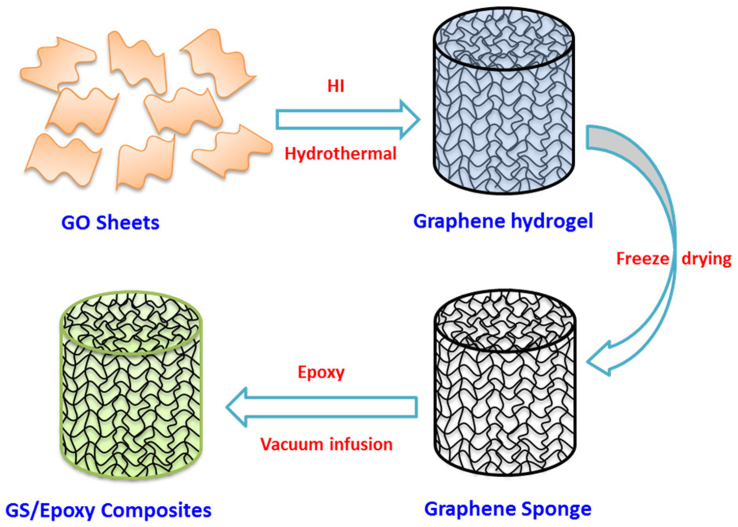
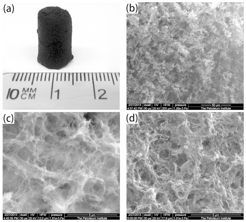
Macroscopic graphene sponges were synthesized from GO solution by a hydrothermal method combined with freeze drying, as shown schematically in Fig. 1. GO is hydrophilic and can be well dispersed into water to form a stable suspension. With hydrothermal treatment, GO was reduced by HI to form hydrophobic graphene. The increased hydrophobicity, van der Waals forces, and stacking interactions of graphene sheets lead to aggregation. After high temperature and high pressure treatment, much water was expelled from the aggregates and a 3D network of compacted graphene sheets was formed. The asprepared 3D graphene is a hydrogel with plenty of water remaining inside. Finally, a black 3D graphene sponge, as shown in Fig. 2 a, is obtained by freeze drying the asprepared graphene hydrogel.
Figure 1. Schematics of the fabrication processes of GS/epoxy nanocomposite.
Figure 2. Image of a GS sample (a), SEM images of inner structure of GS (b) and (c), and GS-75 (d).
The GS obtained is ultralight with a density of 0.022gcm3. The internal morphology of the GS was observed using SEM. Typical low and highmagnification SEM images of GS are shown in Figs. 2 b and c. It is shown from the SEM images that the GS has a 3D porous structure, with pore size in the range of a few to several microns. Interconnected porous with many wrinkles can be seen in the highmagnification SEM image, indicating the formation of 3D network structure via aggregation of reduced GO sheets. The electrical conductivity of GS measured is 0.217Sm. In addition, the electrical conductivity of GSs is isotropic, attributed to the randomly aggregated reduced GO sheets.
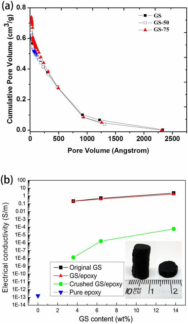
The pore size, density, and properties of GSs can be tuned by predrying the graphene hydrogel before freeze drying. It was found that the predrying process did not change the shape of graphene hydrogel, predrying only resulted in the shrinkage of the sample dimensions and an increase in density. The density of GS50 and GS75 is 0.041 and 0.086gcm3 respectively compared with GSs 0.022gcm3. A crosssectional image of GS75 is shown in Fig. 2d, it is clear that with increasing density, the stack of graphene sheets become compact and the pore size of GS decreases to the range of several hundred nanometers to around 2 microns. The porosimetry measurements show that the specific surface area of GS, GS50, and GS75 is 4.97, 10.99, and 30.44m2cm3, respectively. From the pore volume distribution curve Fig. 3 a, it is clear that GS75 and GS50 presents higher population of mesoporosity and microporosity than the original GS, which leads to the increase of specific surface area. The increased mesoporosity of GS75 and GS50 is also supported by the shape of the hysteresis loop Figure S1. Furthermore, GS75 presents a higher N2 adsorption at low pressures, indicating more micropores than GS50 and GS. At the same time, with an increase in GS density, the interconnection between the graphene sheets is enhanced, which leads to the enhancement of electrical conductivity the electrical conductivities of GS50 and GS75 are 0.509 and 2.32Sm, respectively Fig. 3b.
Figure 3.
(a) The cumulative pore volume of GS, GS-50 and GS-75. (b) Electrical conductivity of pure epoxy, GS, GS/epoxy, and PC-GS/epoxy; and optical images of GS/epoxy composites with different sizes (inset).
As prepared graphene sponges have an open pore structure, thus polymers, such as epoxy resin, can be infused into the sponge. As illustrated in Fig. 1, the graphene sponge is used as a scaffold to infuse with epoxy resin, and the open pores are completely filled. To facilitate the infusion of viscous fluid, GSepoxy mixture were placed in a vacuum chamber for approximately 10min. When completely cured, the composite maintains the same original shape and overall size Fig. 3b inset, indicating that little deformation or shrinkage occurs during the infusion process. The electrical conductivity of GSepoxy composites at different GS content is also shown in Fig. 3b. Pure epoxy resin without GS is almost an insulator with a conductivity of around 1013Sm. The electrical conductivity of GSepoxy, GS50epoxy, and GS75epoxy is 0.21, 0.41, and 1.73Sm, respectively. In addition, the electrical conductivities along three perpendicular directions of the sample were also measured and the results are very close. The isotropic electrical property of the composites is attributed to the random arrangement of graphene sheets in the GS. Compared with pure epoxy, a 12orderofmagnitudes increase in the electrical conductivities of GSepoxy is seen. Remarkably, the electrical conductivity of GSepoxy is very close to that of the pristine GS. Although GS75epoxy suffers highest drop in electrical conductivity, it was only 30 less than that of the pristine GS75, which is still a remarkable improvement compared with that of pure epoxy. Based on our knowledge, the electrical conductivity of GSepoxy produced in this work is at least one order of magnitude higher than the best electrical conductivity of grapheneepoxy composites with similar filler content ever reported Table 1. For the grapheneepoxy composites prepared with traditional methods22,23,24,25,26,27, it is difficult to obtain interconnected graphene network and achieve the electron percolation at low filler content due to the hindering of polymer chain. The good electrical conductivity of GSepoxy reported in this work attribute to the compactly interconnected graphene network constructed in the polymer matrix as proved at discussion section. Furthermore, it should be noted that the electrical conductivity of GSepoxy is directly related to that of the GS, which can be further improved via posttreatment of GS.
Table 1. The electrical conductivity of different grapheneepoxy composites.
| Reference | Type of Filler | Filler content | Electrical Conductivity Sm |
|---|---|---|---|
| Present work | Graphene sponge | 2 wt | 0.21 |
| An et al.22 | Graphene | 2 wt | 0.01 |
| Bao et al.23 | Graphene oxide | 2 wt | 1010 |
| Cao et al.24 | Graphene | 2 wt | 3.28 103 |
| Liang et al.25 | Graphene | 2 wt | 105.5 |
| Ma et al.26 | Graphene | 0.98 vol | 8.3 107 |
| Monti et al.27 | Graphene nanoplatelets | 2 wt | 105 |
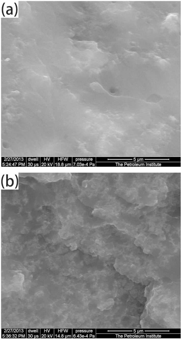
The crosssectional SEM images of GSepoxy nanocomposites are shown in Fig. 4. It can be seen that the porous space in the pristine sponge is almost entirely filled up with epoxy resin. In addition, the GSepoxy nanocomposites show a rough fracture surface with some irregular protuberances, owing to the embedding of graphene sponge in the epoxy matrix. Furthermore, it is clear that the fracture surface of GS75epoxy exhibits a higher roughness than GSepoxy, due to high filler content. In order to further investigate the effect of infusion of epoxy into the network structure of GS, epoxy matrix was washed away by acetone before it was completely cured. After washing, the GS maintains the same original shape and overall size with no visible damage, indicating that infusion of epoxy was carried out smoothly without disturbing the intrinsic structure and morphology of the sponge, and conduction pathways of the graphene networks are preserved.
Figure 4. SEM images of fracture surface of (a) GS/epoxy and (b) GS-75/epoxy samples.
Discussion
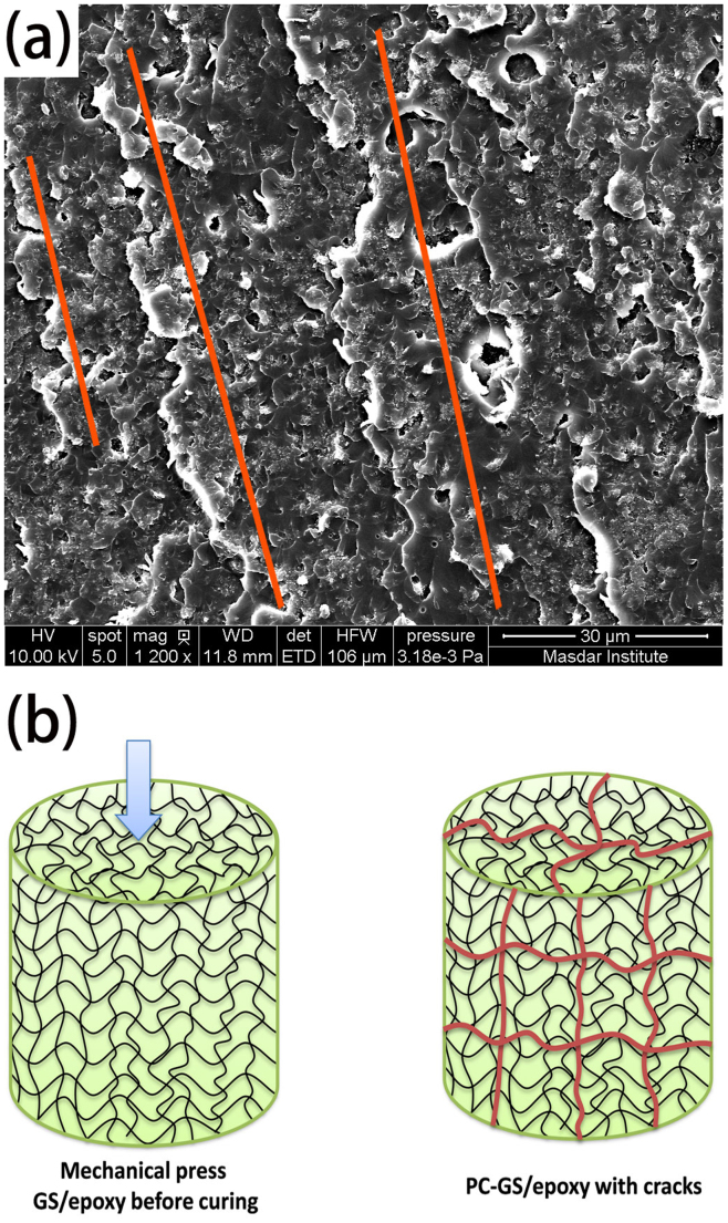
The GSepoxy nanocomposites fabricated have comparable electrical conductivity with pristine GS. From above discussion, it seems that the most important factor for high electrical conductivity should be a 3D compactly interconnected graphene network constructed in the polymer matrix. To further prove the significance of preserving 3D network structure for the electrical conductivity, precrushed GSepoxy PCGSepoxy composite samples were prepared by manually compressing the GSepoxy, before completely curing of the composites. Compared with GSepoxy, as shown in Fig. 3b, the electrical conductivity of the PCGSepoxy samples is at least 5 orders of magnitudes less. As shown in Fig. 5a, many whitecolored wavy ridges and fragments are seen on the fracture surface of PCGSepoxy. The white color of these parts reveals the low electrical conductivity of corresponding materials, indicating that the interconnected graphene network was destroyed, cracks are generated and filled with insulation epoxy by compression. After washing away the epoxy matrix, the 3D GS structure was broken into small pieces, which further proves the damage of 3D structure of GS. Therefore, the preserved interconnected graphene network is critical to achieve high electrical conductivity. As shown schematically in Fig. 5 b, cracks from graphene network can be generated by compression and will be filled by insulation epoxy resin, which lead to the disruption of graphene network and significant drop in the electrical conductivity.
Figure 5.
(a) SEM image of fracture surface of PC-GS/epoxy, red-colored lines indicate the direction of cracks; (b) Schematic of inner structure of GS/epoxy and PC-GS/epoxy, cracks are represented by red-colored lines.
In summary, macroscopic graphene sponges were synthesized from GO solution by a hydrothermal method combined with freeze drying. The pore size, density, and properties of GSs can be tuned by predrying the graphene hydrogel. Highly electrically conductive GSepoxy composites were fabricated by vacuum assisted infusion of epoxy into the GS scaffold. The GSepoxy composites display isotropic electrical behavior, with improved and consistent conductivity measured along any direction. Compared with neat epoxy, the electrical conductivity of GSepoxy has increased around 12 orders of magnitudes. In addition, the electrical conductivity of GSepoxy is very close to that of the pristine GS. The results reveal that the 3D compactly interconnected graphene network constructed in the polymer matrix is critical for high electrical conductivity. The method presented herein is versatile, by filling the excellent interconnected graphene network of GS with other selected materials, other highly electrically conductive composites can be created.
Methods
Materials
Graphite powder with particle size 20m, concentrated sulfuric acid H2SO4, 98, potassium persulfate K2S2O8, phosphorus pentoxide P2O5, sodium nitrate NaNO3, hydrochloric acid HCl, potassium permanganate KMnO4, ethanol, and hydrogen peroxide H2O2, 30, hydroiodic acid HI, 30 were obtained from SigmaAldrich Co. Ltd. 635 Thin Epoxy, a room temperature two component curing system, was obtained from US Composites Inc. All of the materials were directly used without further purification.
Preparation of GO sheets
GO was synthesized from graphite powder with modified Hummers method28,29. First, K2S2O8 10g and P2O5 10g were dissolved in concentrated H2SO4 50ml at 80C. Graphite powder 12g was then added to the acidic solution, and the resulting mixture was stirred at 80C for 4.5h. After cooling to room temperature, the solution was diluted with about 2L deionized DI water and was allowed to stand overnight. The supernatant was decanted, and the pretreated graphite was obtained by centrifugation and washed three times with DI water. The product obtained was dried in air at 100C for 12h. This pretreated graphite powder 2g was put into concentrated H2SO4 50ml with ice bath. KMnO4 7g and NaNO3 1g were added gradually with stirring, and the temperature of the solution was kept below 10C. The mixture was then stirred at 35C for 2h and DI water 96ml was added. The solution was stirred for another 30min, the reaction was then terminated by adding 300ml of DI water and 5ml of 30 H2O2 solution. The mixture was centrifuged and subjected to several cycles of suspension in 5 HCl solution and was separated by centrifugation. In order to completely remove metal ions and acids, the graphite oxide was subjected to cycles of washing with DI water and separated with centrifugation until the pH value of the supernatant reached 6. The GO product was suspended in distilled water to give a viscous, brown dispersion.
Preparation of graphene sponges
The GO suspension obtained was diluted to 2mgml, and was then ultrasonicated in an ultrasonic bath for half an hour. The GSs were subsequently fabricated by hydrothermal treatment of GO suspensions with the assistance of HI19,20. First, 1ml of HI 30 was added into 60ml homogeneous GO 2mgml aqueous solution, and then the mixture was sealed in a 100ml Teflonlined stainless steel autoclave and maintained at 180C for 12h. The reactor was allowed to cool down to room temperature RT, and the asprepared graphene hydrogels were taken out from reactor and dipped into distilled water for 24h to remove the residual HI. To control the density of the final GS, water from the original graphene hydrogels were partially removed in air through evaporation at RT. Finally, the samples were freezed with liquid nitrogen and freezedried in vacuum to remove the remaining water to obtain GS. Three type samples with 0, 50, and 75 percent by weight wt water removed from graphene hydrogel before freeze drying were prepared and named as GS, GS50, and GS75 respectively.
Preparation of GSepoxy nanocomposites
Epoxy and curing agent were mixed homogenously via magnetic stirring. The weight ratio of epoxy resin to curing agent was kept at 31. The GS prepared was completely immersed into the epoxy mixture. Then the mixture was placed in a vacuum chamber for approximately 10min for the GS to be infused with epoxy and to remove air bubbles. Finally, the GSepoxy sample was taken out from epoxy mixture and cured at room temperature for 24h. Excessive epoxy adhered on the sponge surface was removed before curing. The graphene loading in the composite was determined by measuring the weight of the graphene sponge before infusion and of the composite after epoxy infusion.
Characterization
The morphology of GS and GSepoxy nanocomposites were examined by a FEI Quanta FEG 250 scanning electron microscopy SEM. Images of GS and GSepoxy composites were taken using a Canon digital camera IXUS 70. Porosimetry measurements were carried out using a high resolution Micromeritics 3Flex adsorption instrument. The 3Flex Micromeritics was equipped with highvacuum system, and three 0.1 Torr pressure transducers. Electrical properties of the GS and GSepoxy composites were measured at RT with a twoprobe method using an insulation resistance meter TH 2684A 10k 100T and an ADM930 Digital Multimeter 0.1 40M. The specimens used for the conductivity measurement were silverpasted to minimize the contact resistance between the composites and the electrodes. The electrical conductivity, , can be calculated from the equation HRA, where H, R, and A are thickness, resistance, and area, respectively.
Author Contributions
Y.L. conceived and designed the project. Y.L., Y.S., K.P. and S.A. fabricated the materials and carried the experiments. All authors contributed to the data and discussions regarding the research. Y.L. and K.L. wrote the manuscript.
Supplementary Material
Figure S1
Acknowledgments
The authors are grateful to the financial support by the Internal Research Funds of Khalifa University of Science, Technology Research No. 21011A and No. 210008.
References
- Balandin A. A. et al. Superior thermal conductivity of singlelayer graphene. Nano Lett. 8, 902–907. 2008. [DOI] [PubMed] [Google Scholar]
- Castro Neto A. H., Guinea F., Peres N. M. R., Novoselov K. S. Geim A. K. The electronic properties of graphene. Rev. Mod. Phys. 81, 109–162. 2009. [Google Scholar]
- Geim A. K. Novoselov K. S. The rise of graphene. Nat. Mater. 6, 183–191. 2007. [DOI] [PubMed] [Google Scholar]
- Novoselov K. S. et al. Twodimensional gas of massless Dirac fermions in graphene. Nature 438, 197–200. 2005. [DOI] [PubMed] [Google Scholar]
- Lee C., Wei X. D., Kysar J. W. Hone J. Measurement of the elastic properties and intrinsic strength of monolayer graphene. Science 321, 385–388. 2008. [DOI] [PubMed] [Google Scholar]
- Li Y. Q., Yu T., Yang T. Y., Zheng L. X. Liao K. BioInspired Nacrelike Composite Films Based on Graphene with Superior Mechanical, Electrical, and Biocompatible Properties. Adv. Mater. 24, 3426–3431. 2012. [DOI] [PubMed] [Google Scholar]
- Li Y. Q., Umer R., Samad Y. A., Zheng L. X. Liao K. The effect of the ultrasonication pretreatment of graphene oxide GO on the mechanical properties of GOpolyvinyl alcohol composites. Carbon 55, 321–327. 2013. [Google Scholar]
- Li Y. Q., Yang T. Y., Yu T., Zheng L. X. Liao K. Synergistic effect of hybrid carbon nantubegraphene oxide as a nanofiller in enhancing the mechanical properties of PVA composites. J. Mater. Chem. 21, 10844–10851. 2011. [Google Scholar]
- Song S. H. et al. Enhanced Thermal Conductivity of EpoxyGraphene Composites by Using NonOxidized Graphene Flakes with NonCovalent Functionalization. Adv. Mater. 25, 732–737. 2013. [DOI] [PubMed] [Google Scholar]
- Huang X., Qi X. Y., Boey F. Zhang H. Graphenebased composites. Chem. Soc. Rev. 41, 666–686. 2012. [DOI] [PubMed] [Google Scholar]
- Balandin A. A. Thermal properties of graphene and nanostructured carbon materials. Nat. Mater. 10, 569–581. 2011. [DOI] [PubMed] [Google Scholar]
- Thomassin J. M., Jerome C., Pardoen T., Bailly C., Huynen I., Detrembleur C. Polymercarbon based composites as electromagnetic interference EMI shielding materials. Mater. Sci. Eng. RRep. 74, 211–32. 2013. [Google Scholar]
- Hong W. J., Xu Y. X., Lu G. W., Li C. Shi G. Q. Transparent graphenePEDOTPSS composite films as counter electrodes of dyesensitized solar cells. Electrochem. Commun. 10, 1555–1558. 2008. [Google Scholar]
- Chen Z. P., Xu C., Ma C. Q., Ren W. C. Cheng H. M. Lightweight and Flexible Graphene Foam Composites for HighPerformance Electromagnetic Interference Shielding. Adv. Mater. 25, 1296–1300. 2013. [DOI] [PubMed] [Google Scholar]
- Vuluga D. et al. Straightforward synthesis of conductive graphenepolymer nanocomposites from graphite oxide. Chem. Comm. 47, 2544–2546. 2011. [DOI] [PubMed] [Google Scholar]
- Wu C. et al. Highly Conductive Nanocomposites with ThreeDimensional, Compactly Interconnected Graphene Networks via a SelfAssembly Process. Adv. Funct. Mater. 23, 506–513. 2013. [Google Scholar]
- Zhong Y. J., Zhou M., Huang F. Q., Lin T. Q. Wan D. Y. Effect of graphene aerogel on thermal behavior of phase change materials for thermal management. Sol. Energ. Mat. Sol. Cells 113, 195–200. 2013. [Google Scholar]
- Li Y. Q. et al. Synergistic toughening of epoxy with carbon nanotubes and graphene oxide for improved longterm performance. Rsc Adv. 3, 8849–8856. 2013. [Google Scholar]
- Bi H. C. et al. Spongy Graphene as a Highly Efficient and Recyclable Sorbent for Oils and Organic Solvents. Adv. Funct. Mater. 22, 4421–4425. 2012. [Google Scholar]
- Zhao J. P., Ren W. C. Cheng H. M. Graphene sponge for efficient and repeatable adsorption and desorption of water contaminations. J. Mater. Chem. 22, 20197–20202. 2012. [Google Scholar]
- Chen W. F. Yan L. F. In situ selfassembly of mild chemical reduction graphene for threedimensional architectures. Nanoscale 3, 3132–3137. 2011. [DOI] [PubMed] [Google Scholar]
- An J. E. Jeong Y. G. Structure and electric heating performance of grapheneepoxy composite films. Eur. Polym. J. 49, 1322–1330. 2013. [Google Scholar]
- Bao C. L. et al. In situ preparation of functionalized graphene oxideepoxy nanocomposites with effective reinforcements. J. Mater. Chem. 21, 13290–13298. 2011. [Google Scholar]
- Cao L. J. et al. How a biobased epoxy monomer enhanced the properties of diglycidyl ether of bisphenol A DGEBAgraphene composites. J Mater. Chem. A 1, 5081–5088. 2013. [Google Scholar]
- Liang J. J. et al. Electromagnetic interference shielding of grapheneepoxy composites. Carbon 47, 922–925. 2009. [Google Scholar]
- Ma J. et al. Covalently bonded interfaces for polymergraphene composites. J. Mater. Chem. A 1, 4255–4264. 2013. [Google Scholar]
- Monti M. et al. Morphology and electrical properties of grapheneepoxy nanocomposites obtained by different solvent assisted processing methods. Compos. Pt. AAppl. Sci. Manuf. 46, 166–172. 2013. [Google Scholar]
- Kovtyukhova N. I. et al. Layerbylayer assembly of ultrathin composite films from micronsized graphite oxide sheets and polycations. Chem. Mater. 11, 771–778. 1999. [Google Scholar]
- Geng J. Jung H. Porphyrin Functionalized Graphene Sheets in Aqueous Suspensions From the Preparation of Graphene Sheets to Highly Conductive Graphene Films. J. Phys. Chem. C 114, 8227–8234. 2010. [Google Scholar]
Associated Data
This section collects any data citations, data availability statements, or supplementary materials included in this article.
Supplementary Materials
Figure S1


