Abstract
A two-point binding mechanism for the cationic rhodium(I)-catalyzed carbonyl-directed catalytic asymmetric hydroboration of a cyclic γ,δ-unsaturated amide is investigated using density functional theory. Geometry optimizations and harmonic frequency calculations for the model reaction are carried out using the basis set 6-31+G** for C, O, P, B, N, and H and LANL2DZ for Rh atoms. The Gibbs free energy of each species in THF solvent is obtained based on the single-point energy computed using the PCM model at the ECP28MWB/6-311+G(d,p) level plus the thermal correction to Gibbs free energy by deducting translational entropy contribution. The Rh-catalyzed reaction cycle involves the following sequence of events: (1) chelation of the cyclic γ,δ-unsaturated amide via alkene and carbonyl complexation in a model active catalytic species, [Rh(L2)2S2]+, (2) oxidative addition of pinacol borane (pinBH), (3) migratory insertion of the alkene double bond into Rh–H (preferred pathway) or Rh–B bond, (4) isomerization of the resulting intermediate, and finally, (5) reductive elimination to form the B–C or H–C bond with regeneration of the catalyst. Free energy profiles for potential pathways leading to the major γ-borylated product are computed and discussed in detail. The potential pathways considered include (1) pathways proceeding via migratory insertion into the Rh–H bond (pathways I, I-1, and I-2), (2) a potential pathway proceeding via migratory insertion into the Rh–B bond (pathway II), and two potential competing routes to a β-borylated byproduct (pathway III). The results find that the Rh–H migratory insertion pathway I-2, followed in sequence by an unanticipated isomerization via amide rotation and reductive elimination, is the most favorable reaction pathway. A secondary consequence of amide rotation is access to a competing β-hydride elimination pathway. The pathways computed in this study are supported by and help explain related experimental results.
Keywords: Density functional theory (DFT), rhodium-catalyzed, catalysis mechanism, catalytic asymmetric hydroboration, two-point binding mechanism
Recent advances in methods utilizing organoboranes in synthesis,1−10 especially chiral organoboranes,11−25 have renewed interest in transition metal catalyzed hydroborations.26−34 Rhodium-catalyzed hydroborations, in particular, often exhibit versatile chemo-, regio-, and diastereoselectivity,35−41 and among the recent advances in this methodology, Takacs et al. reported a series of studies on the carbonyl-directed catalytic asymmetric hydroboration (directed CAHB) of two-point binding unsaturated amides and esters.42−46 A number of mechanistic studies, both experimental47−49 and theoretical, of rhodium-catalyzed hydroboration have been reported. However, the prior computational work on the rhodium-catalyzed reaction focuses on what can be categorized as the reaction via a one-point binding mechanism (or nondirected catalyzed hydroboration) of a simple alkene substrate, often styrene, and most often employing a neutral (i.e., [LnRhCl]2),50−52 rather than cationic (e.g., LnRh(I)BF4),53,54 complex. The model active catalytic species in the prior computational studies, typically (H3P)2RhCl, is a neutral d8 closed-shell rhodium complex with a T-shaped geometry. The key mechanistic steps are oxidative addition of borane to (H3P)2RhCl followed by the alkene coordination, migratory insertion, and reductive elimination.
In the present work on the directed rhodium-catalyzed hydroboration, the alkene substrate also contains a nearby amide functionality. The carbonyl group of amide and C=C π bond of alkene complex to the cationic rhodium(I) from the same face of the cyclopentenyl ring system, chelating the metal in a cis fashion. Therefore, we call this a two-point binding mechanism. Two-point binding is known to play an important role in directing the selectivity in common variants of rhodium(I)-catalyzed asymmetric hydrogenation.55,56
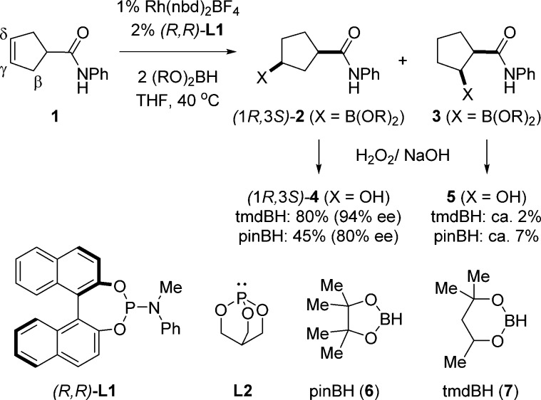
Figure 1 shows the rhodium-catalyzed amide-directed CAHB of a cyclic γ,δ-unsaturated amide 1 leading to the γ-borylated (1R,3S)-2 as the major product.57 Note that boron is introduced on the more sterically encumbered face of the alkene, cis with respect to the amide functionality, as anticipated for a carbonyl-directed reaction; little (i.e., typically 3% or less) of the isomeric trans-γ-borylated compound is found. However, (1R,3S)-2 is usually accompanied by a small amount of the β-borylated isomer 3.
Figure 1.
Amide-directed catalytic asymmetric hydroboration reaction (CAHB) of cyclic γ,δ-unsaturated amide 1.
We investigated energy profiles using density functional theory (DFT) calculations for multiple potential pathways involving a two-point binding mechanism for a model reaction closely related to the CAHB reaction shown in Figure 1. To reduce the degrees of freedom and thereby lower the required computing time, two simplifications are made (Figure 2). A caged phosphite ligand (i.e., 2,6,7-trioxa-1-phosphabicyclo[2.2.2] octane (L2)) is substituted for (BINOL)PN(Me)Ph (L1), the chiral ligand used in experimental studies, and pinacolborane (pinBH, 6) is used in place of the unsymmetrical borane (tmdBH, 7) found to be preferable in the experimental work. The reaction cycle is initiated by the active cationic catalytic species [Rh(L2)2S2]+, a tetracoordinate square-planar complex, where L2 represents the caged-ligand and S represents THF, the reaction solvent. We report the energetics of all steps in the pathways leading to the γ-borylated product (1R*,3S*)-262 and partially explore pathways leading to the β-borylated product 3.
Figure 2.
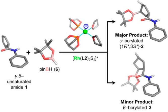
The model reaction is illustrated with the optimized geometries of reactants, catalyst, and major and minor products. (Note: Most H atoms, except for the polar and reactive ones, are hidden for clarity.).
Computational Details
The reactants, products, intermediates (Im), and transition-state (TS) geometries in the model reaction were optimized using the DFT/B3LYP58,59 method implemented in the Gaussian 09 package.60 Gradient optimizations were carried out using the 6-31+G** basis set for C, O, P, B, N, and H and LANL2DZ for Rh atoms. The stationary frequency calculations at 298.15 K and 1 atm were performed at the same level for each of the optimized structures to examine any imaginary frequency or the corresponding vibrational modes to obtain the thermal correction to Gibbs free energy. The intrinsic reaction coordinate (IRC) calculations for each TS structure were performed to illustrate the energy landscapes leading to the TS geometry from the two neighboring minima corresponding to the species before and after the respective steps. The single-point energies of all the species in this reaction were calculated using 6-311+G** basis set for C, O, P, B, N, and H and ECP28MWB for Rh atoms and the PCM model for the tetrahydrofuran (THF) solvent, all implemented in Gaussian 09.
We evaluated the free-energy changes at 298.15 K in two different ways. In the first way, we computed the free-energy changes according to formula 1(61) in which Gcorrect represents the thermal correction to Gibbs free energy in the gas phase and Esolvent is the single-point energy of the same molecule in THF solvent with a larger basis set. In this way the translational, rotational, and vibrational contributions in gas phase were all taken into account in the estimation of the free energy. With this correction, we find that the relative energy does not differ markedly from that before the correction for those elementary steps involving neither the formation of adduct nor the release of product. However, very significant relative energy differences were observed in those elementary processes that involve either the formation of adduct or the release of product (see the Supporting Information, Table S1). For the reaction in the gas phase, this may be reasonable due to the significant entropy contribution (G = H – TS). However, it seems that, when in solution, the entropy contribution is overestimated for the steps that involve either the formation of adduct or the release of product, because the released molecules encounter limited space for translational motion within in the solvent cage.63,64 The overestimated entropy contribution should mainly come from the translational entropy. Therefore, we approached the problem in a second way; we deducted the translational entropy and evaluated the free-energy change according to formula 2. Note that the second method underestimates the entropy effects because translation movements are not completely suppressed in solution. However, we believe that excluding the translational entropy should make calculated results closer to experiment, and consequently, the ensuing discussion of mechanism will be based on the results obtained from this second method.
| 1 |
| 2 |
Results and Discussions
1. General Considerations
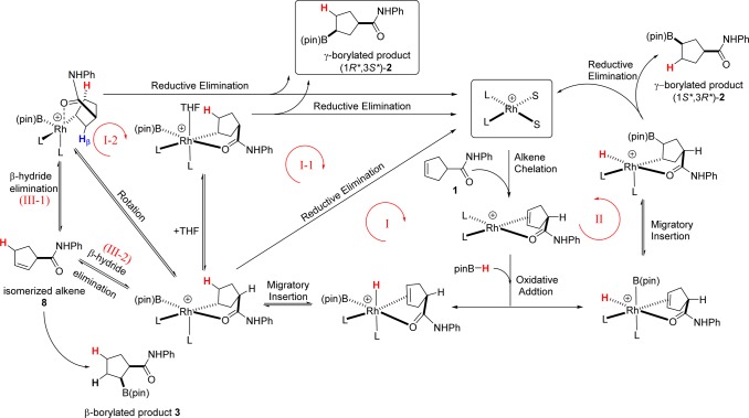
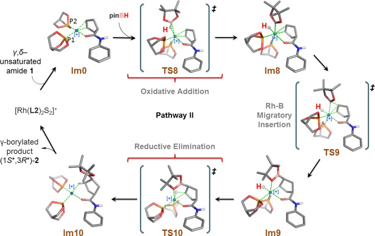
We studied the model reaction shown in Figure 2 while invoking two-point binding of the substrate. A series of possible reaction cycles (i.e., pathways I, II, and III, Figure 3) were considered in our calculations. The first step, common in all of the pathways considered, is complexation of the alkene substrate (i.e., N-phenylcyclopent-3-enecarboxamide (1)) to the model active catalyst [Rh(L2)2S2]+. Note that each intermediate and transition state considered in our calculations is labeled Im or TS, respectively, followed by an identifying compound number. Oxidative addition of pinacolborane (pinBH, 6) affords the first intermediate rhodium complex, Im1. Reaction proceeds via migratory insertion of the alkene bond into the Rh–H or Rh–B bond with subsequent reductive elimination to form the B–C or C–H bond, respectively. In Figure 3, the cycle proceeding via migratory insertion into the Rh–H bond and leading to the major γ-borylated product (1R*,3S*)-2 is labeled pathway I; the cycle proceeding via migratory insertion into the Rh–B bond and leading to isomeric γ-borylated product (1S*,3R*)-2 is labeled pathway II.
Figure 3.
Three possible reaction cycles with variants evaluated for the proposed two-point substrate binding mechanism. (The hydrogen atoms highlighted in red indicate incorporation from pinB–H.).
Two other pathways, labeled pathways I-1 and I-2, differ from pathway I in the details associated with the reductive elimination step but afford the same γ-borylated product as pathway I. We also considered potential competing pathways leading to the isomeric β-borylated product 3, as outlined in pathway III. The relative free energies for all the species considered in various pathways of the model reaction are given in Table 1. In each case, the free energies for intermediates and transition states (kcal/mol) are relative to the total free energies of reactants (i.e., the catalyst [Rh(L2)2S2]+ + substrate + pinBH).
Table 1. Relative Gibbs Free Energies (ΔG in kcal/mol) for All Species in the Model Reaction.
| pathway I | ΔG | pathway II | ΔG | pathway III | ΔG |
|---|---|---|---|---|---|
| [Rh(L2)2S2]+ + substrate + pinBHa | 0 | [Rh(L2)2S2]+ + substrate + pinBHa | 0 | ||
| Im0 + 2 THF + pinBH | 0.18 | Im0 + 2 THF + pinBH | 0.18 | ||
| TS1 + 2 THF | 16.09 | TS8 + 2 THF | 22.20 | TS11 + 2 THF | 17.13 |
| Im1 + 2 THF | 4.07 | Im8 + 2 THF | 7.64 | Im11 + 2 THF | 12.13 |
| TS2 + 2 THF | 5.30 | TS9 + 2 THF | 14.88 | TS12 + 2 THF | 17.30 |
| Im2 + 2 THF | 0.85 | Im9 + 2 THF | 5.43 | Im12 + 2 THF | 15.86 |
| TS3 + THF | 8.67 | TS10 + 2 THF | 24.83 | TS13 + 2 THF | 32.78 |
| Im3 + THF | 8.25 | Im10 + 2 THF | –1.72 | Im13 + 2 THF | 5.71 |
| TS4 + THF | 29.26 | TS14 + 2 THF | 13.06 | ||
| Im4 + THF | –16.35 | Im14 + 2 THF | 8.81 | ||
| TS5 + 2 THF | 8.59 | TS15 + 2 THF | 29.53 | ||
| Im5 + 2 THF | 3.08 | ||||
| TS6 + 2 THF | 19.84 | ||||
| Im6 + 2 THF | –3.29 | ||||
| TS7 + 2 THF | 27.40 | ||||
| Im7 + 2 THF | –2.73 | ||||
| (1R*,3S*)-2 + [Rh(L2)2S2]+ | –17.26 | (1S*,3R*)-2 + [Rh(L2)2S2]+ | –17.26 |
Sum of the free energies of all reactants is set to zero.
2. Pathway I: Migratory Insertion into the Rh–H Bond
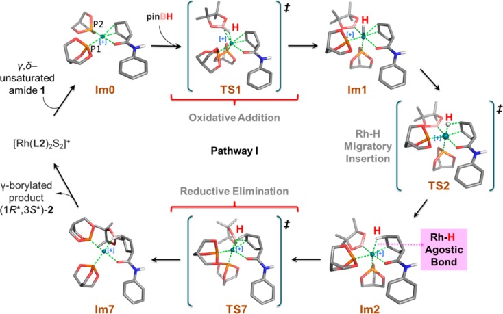
According to the proposed two-point binding mechanism, the substrate first chelates to [Rh(L2)2S2]+ by displacing two solvent molecules to form the complex labeled Im0. As shown in Figure 4, Im0 is a square-planar tetracoordinate rhodium(I) complex with Cs symmetry. The borane, pinBH, can add to Im0 from above or below the plane containing the metal leading to enantiomeric products. Although the experimental studies directed toward CAHB use chiral ligands, the model reaction incorporates achiral phosphite ligands. Therefore, in contrast to the experimental studies, for which the two oxidative addition approach pathways are diastereomeric, the above and below plane pathways in the model reaction are enantiomeric and equivalent in energy. Consequently, enantioselectivity is not directly relevant to the model reaction, and we only calculate pinBH attack from above the plane in pathway I (Figure 4) leading to the formation of (1R*,3S*)-2.
Figure 4.
Optimized structures for pathway I.
Oxidative addition of pinBH proceeds via calculated transition state TS1; its structure and geometric parameters are listed in Table 2. It can be noted that, in the transition state, pinBH is positioned almost parallel to the plane containing Rh placing the H atom directly on top of the metal. The caged ligand labeled P2 is then displaced downward with respect to the plane, ending at pseudoaxial position. The Rh—B and Rh—H bond lengths are 2.368 and 1.831 Å, respectively. The calculated free energy of activation for the formation of TS1 is 15.9 kcal/mol. The intermediate formed via oxidative addition of pinBH to Im0 is the hexacoordinate octahedral complex Im1, which is calculated to lie approximately 3.9 kcal/mol higher in energy than the Im0. The Rh—H bond in Im1 is oriented parallel to the Cγ=Cδ double bond of alkene substrate, and the latter remains coordinated to the metal.
Table 2. Selected Bond Lengths (Å) for the Intermediates and Transition States of Pathways I and II.
| Rh–Cγ | Rh–Cδ | Cγ–Cδ | Rh–Ha | Rh–B | Rh–P1 | Rh–P2 | Rh–Ob | Cδ–H | Cγ–B | |
|---|---|---|---|---|---|---|---|---|---|---|
| Im0 | 2.293 | 2.293 | 1.384 | 2.325 | 2.217 | |||||
| TS1 | 2.448 | 2.410 | 1.370 | 1.831 | 2.368 | 2.256 | 2.239 | 2.521 | ||
| Im1 | 2.375 | 2.371 | 1.381 | 1.576 | 2.049 | 2.274 | 2.413 | 2.347 | ||
| TS2 | 2.239 | 2.329 | 1.415 | 1.612 | 2.050 | 2.313 | 2.350 | 2.342 | 1.687 | |
| Im2 | 2.103 | 2.425 | 1.506 | 1.944 | 2.050 | 2.340 | 2.220 | 2.329 | 1.166 | |
| TS3 | 2.107 | 2.790 | 1.540 | 2.514 | 2.043 | 2.482 | 2.182 | 2.323 | 1.101 | |
| Im3 | 2.146 | 3.062 | 1.537 | 3.092 | 2.050 | 2.513 | 2.204 | 2.342 | 1.089 | |
| TS4 | 2.490 | 3.350 | 1.548 | 3.387 | 2.188 | 2.259 | 2.230 | 2.588 | 1.089 | 1.787 |
| Im4 | 3.537 | 1.558 | 4.957 | 2.194 | 2.208 | 2.174 | 1.089 | 1.576 | ||
| TS5 | 2.105 | 2.916 | 1.550 | 2.709 | 2.039 | 2.465 | 2.184 | 2.298 | 1.096 | |
| Im5 | 2.104 | 3.127 | 1.549 | 3.057 | 2.026 | 2.456 | 2.220 | 2.180 | 1.091 | |
| TS6 | 2.293 | 3.483 | 1.573 | 3.529 | 2.118 | 2.283 | 2.216 | 2.176 | 1.089 | 1.957 |
| Im6 | 1.568 | 2.194 | 2.211 | 2.134 | 1.580 | |||||
| TS7 | 2.283 | 2.555 | 1.545 | 2.059 | 2.311 | 2.238 | 2.194 | 2.759 | 1.128 | 1.719 |
| Im7 | 2.011 | 2.208 | 2.197 | 2.148 | 1.123 | 1.580 | ||||
| TS8 | 2.385 | 2.337 | 1.379 | 1.704 | 2.437 | 2.269 | 2.357 | 2.355 | ||
| Im8 | 2.325 | 2.360 | 1.385 | 1.535 | 2.113 | 2.275 | 2.482 | 2.279 | ||
| TS9 | 2.121 | 2.288 | 1.461 | 1.533 | 2.298 | 2.364 | 2.307 | 2.275 | 1.899d | |
| Im9 | 2.123 | 3.003 | 1.550 | 1.541 | 3.022 | 2.496 | 2.199 | 2.265 | 1.561d | |
| TS10 | 2.228 | 3.105 | 1.553 | 1.569 | 3.087 | 2.380 | 2.188 | 2.487 | 1.580c | 1.570d |
| Im10 | 2.801 | 1.560 | 1.965 | 2.195 | 2.206 | 2.156 | 1.124c |
Rh–H denotes the distance of Rh to the H originally bonded to B in pinBH.
O indicates the oxygen atom of the carbonyl moiety.
The value in italics is the distance of Cγ–H;
The value in italics is the distance of Cδ–B;
From the geometry calculated for Im1, migration of the H atom from rhodium to Cδ is facile via transition state TS2.65 The calculated free energy barrier for migratory insertion of the alkene into the Rh—H bond is approximately 1.2 kcal/mol, substantially lower than that required for the first step. Intermediate Im2 is about 3.2 kcal/mol more stable than its precursor, Im1. As shown in Figure 4 and in Tables 2 and 3, Im2 is a distorted octahedral complex; the bond angle of Cγ—Rh—P1 is reduced sequentially from 176.78° in Im1 to 168.01° in TS2 and finally to 162.02° in Im2. Concomitant with formation of the Rh—Cγ and Cδ—H bonds, the Cγ=Cδ π bond is broken to form a single bond. The Rh—Cγ, Cδ—H and Cγ—Cδ bond lengths in Im2 are found to be 2.103, 1.116, and 1.506 Å, respectively. The Rh—H bond is continually elongated from that in Im1 (1.576 Å) through TS2 (1.612 Å) to Im2 (1.944 Å). Nonetheless, the relatively short contact distance persisting in Im2 indicates a weak but significant agostic interaction remains between Rh—HCδ.
Table 3. Selected Angles (deg) for the Intermediates and Transition States of Pathways I and II.
| ORhBa | CγRhP1 | CγRhH | CγRhB | |
|---|---|---|---|---|
| Im0 | 162.12 | |||
| TS1 | 123.19 | 160.83 | 108.48 | 109.05 |
| Im1 | 175.60 | 176.78 | 99.32 | 92.03 |
| TS2 | 176.11 | 168.01 | 82.40 | 91.34 |
| Im2 | 173.12 | 162.02 | 66.29 | 91.95 |
| TS3 | 166.68 | 171.08 | 56.05 | 91.37 |
| Im3 | 172.82 | 176.68 | 45.88 | 89.26 |
| TS4 | 129.25 | 161.06 | 44.33 | |
| TS5 | 132.52 | 169.61 | 52.87 | 97.80 |
| Im5 | 95.17 | 164.57 | 46.09 | 101.96 |
| TS6 | 98.27 | 171.07 | 37.80 | 52.50 |
| TS7 | 130.77 | 154.08 | 62.24 | 43.96 |
| TS8 | 114.65 | 164.48 | 101.04 | 110.60 |
| Im8 | 97.03 | 170.96 | 90.69 | 104.76 |
| TS9 | 101.70 | 175.15 | 90.45 | 85.69 |
| Im9 | 175.80 | 90.92 | 57.81 | |
| TS10 | 174.02 | 45.19 | 56.81 |
O indicates the oxygen atom of the carbonyl moiety.
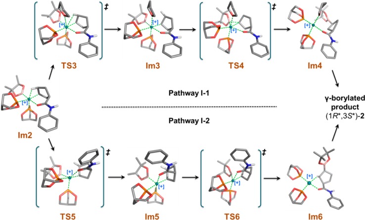
The final step in the two-point binding mechanism is reductive elimination to form the pinB–Cγ bond. As shown in Figure 4 and in Table 2, TS7 is the transition state for reductive elimination. The weak Rh–HCδ agostic interaction is maintained in TS7 while the interaction between B, Rh, and Cγ assumes a triangular pattern. A rather high free energy barrier, 26.5 kcal/mol, is calculated for the formation of TS7. After reductive elimination, the tetracoordinate intermediate Im7 is formed, which, in turn, leads to the γ-borylated product (1R*,3S*)-2 and regenerates the Rh-catalyst. As evident from the high barrier of formation of TS7, it is difficult for the pinB group to migrate directly to Cγ through TS7 while maintaining the agostic Rh–HCδ interaction. We explored two other pathways (labeled I-1 and I-2), which may provide much lower energy pathways. Both pathways proceed via breakage of the Rh–HCδ agostic interaction and afford the γ-borylated product (1R*,3S*)-2, as shown in Figure 5.
Figure 5.
Optimized structures for pathways I-1 and I-2.
In pathway I-1, we explored a pathway in which a molecule of solvent (i.e., THF) is explicitly reintroduced into the mechanism. THF adds to Im2, breaking the agostic interaction; the barrier for the THF addition step is only 7.8 kcal/mol. The resulting product, Im3, is a stable hexacoordinate octahedral complex, in which the calculated distance between Rh and the O atom of THF is 2.343 Å. Reductive elimination forms the pinB–C bond, leading to release of the γ-borylated product. The calculated migration transition state (TS4) shows one imaginary vibrational mode in which the B atom clearly moves further away from the metal atom and gets closer to Cγ atoms to form the B–Cγ bond and break the Rh–B bond. The activation energy barrier from Im3 to TS4 is relatively high (21.0 kcal/mol). Tetracoordinate intermediate Im4 would be generated in the process leading to release of the γ-borylated product and regeneration of the catalyst.
An alternative pathway involving isomerization of Im2 is found to be more favorable than the two described above. In pathway I-2, the Rh-coordinated carbonyl group of the amide moiety in Im2 rotates approximately 78° from an equatorial to an axial position to form Im5; the O—Rh—B angle is 173.2° in Im2, 132.52° in TS5, and 95.17° in Im5 (Table 3). The long Rh—H distance in Im5 (i.e., 3.057 Å) indicates that the Rh—HCδ agostic interaction has been broken. The energy barrier for rotation to TS5 (7.7 kcal/mol) is roughly equal to that for adding THF as proposed in pathway I-1. Although one agostic bond is broken in Im5, a new agostic interaction is formed with the β-hydrogen (Hβ) of the cyclic alkene; the calculated Rh-to-Hβ distance is 2.600 Å. Both the reactant (Im2) and product (Im5) possess a distorted octahedral geometry in which the metal–hydrogen agostic interaction remains conserved; therefore, the resulting two structures can be considered as simple pseudorotational isomers. Im5 undergoes pinB to Cγ reductive elimination via the calculated transition state TS6 with an activation barrier of 16.8 kcal/mol. The activation barrier of the B—C reductive elimination is roughly 10 kcal/mol lower than that the corresponding step in pathway I (i.e., TS7, 26.5 kcal/mol). The major difference between the two transition states is the location of the weak agostic interaction, which is trans to the migrating B atom in TS6, whereas the C=O and Rh interaction may exert a stronger trans effect on the migrating group in TS7. TS6 shows one imaginary vibrational mode similar to TS4 and TS7 as described previously. The tetracoordinate intermediate Im6 then leads to the γ-borylated product with regeneration of the catalyst.
A comparison of these three pathways (I, I-1, and I-2) and their respective free-energy profiles is illustrated in Figure 6. We find that the reductive elimination step should be the rate-determining step for all three possibilities examined. In pathway I, the reductive elimination occurs via a single transition state (TS7), whereas pathways I-1 and I-2 involve two-step transformation via an intermediate (Im3 for I-1 and Im5 for I-2) and two transition states (TS3, TS4 for I-1 and TS5, TS6 for I-2). The overall energy barriers of the rate determining step for the three pathways, in decreasing order, is as follows: pathway I-1 (28.41 kcal/mol) > pathway I (26.54 kcal/mol) > pathway I-2 (18.99 kcal/mol), indicating that pathway I-2 is the most favorable for formation of γ-borylated product (1R*,3S*)-2 in the model reaction.
Figure 6.
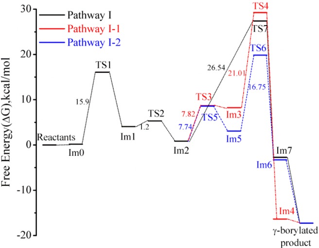
Comparison of the potential energy profiles for pathways I, I-1, and I-2.
3. Pathway II: Migratory Insertion into the Rh–B Bond
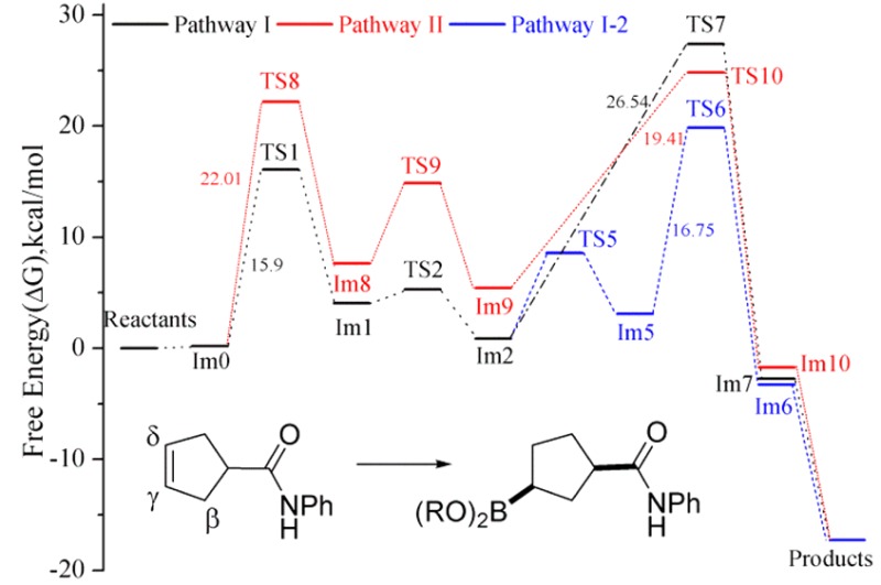
A recurring question in the mechanism of rhodium-catalyzed hydroboration is which migratory insertion pathway is preferred, Rh–H or Rh–B; the latter often referred to as the dehydrogenative borylation pathway.50,52,66−69 To address this question, we examined pathway II, which differs from the family of mechanisms described under pathway I in that pathway II involves the migratory insertion of the coordinated alkene into the Rh–B bond.70−72 To accommodate the desired migratory insertion, pinBH adds to Im0 in a direction more perpendicular (rather than parallel, as previously examined) to the coordination plane encompassing Rh (Figure 7). Therefore, the intermediate obtained in the first step of pathway II, i.e., Im8, differs structurally from the previously described Im1. In Im8, the Rh–B bond occupies a position parallel to the alkene double bond while the Rh–H bond resides in the equatorial plane perpendicular to the alkene. The imaginary vibrational frequency of TS8 clearly shows B–H bond breaking and Rh–B bond formation modes. The activation free energy barrier leading to TS8 is calculated to be 22.0 kcal/mol, approximately 6 kcal/mol higher than that found for pathway I (see Figure 8). The free energies listed in Table 1 indicate the intermediate Im8 is less stable (by about 3.5 kcal/mol) than Im1.
Figure 7.
Optimized structures for pathway II.
Figure 8.
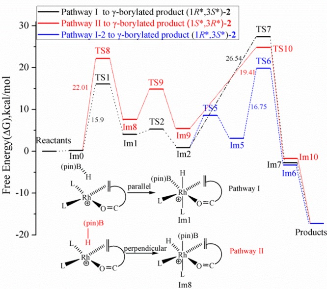
Comparison of the potential energy profiles for pathways I, I-2, and II.
Step 2 of pathway II involves the key migratory insertion of the alkene into the Rh–B bonding, leading to formation of the B–Cδ bond. We find that this step encounters a free-energy barrier of approximately 7 kcal/mol, whereas the analogous transition in pathway I (alkene insertion into the Rh–H bond) is almost barrierless. In addition, the resulting intermediate Im9 is roughly 4.6 kcal/mol less stable than the previously described intermediate Im2. Structurally, Im9 still maintains an octahedral core around the Rh as an O atom of the pinacol moiety now coordinates to Rh.73 Reductive elimination forms the H–Cγ bond and the square planar intermediate Im10 which again eventually affords the γ-borylated product (1S*,3R*)-2. This reductive elimination step has a calculated free energy of activation of approximately 20 kcal/mol, making it not only the highest overall energy barrier in pathway II but higher than the highest overall barrier calculated for pathway I-2.74
It is worth noting at this point that oxidative addition of pinBH from above the plane of Im0 (i.e., the same mode of addition described above), the Rh–H migratory insertion pathways I, I-1, and I-2 lead to the stereoisomer of the γ-borylated product designated (1R*,3S*)-2 whereas the Rh–B insertion pathway II leads to the enantiomeric structure designated (1S*,3R*)-2. As noted above, the top- and bottom-face approaches are enantiotopic in the model reaction, where achiral phosphite ligands are employed, and therefore must be energetically equivalent. However, the enantiodivergent Rh–H and Rh–B insertion pathways are of significance when chiral ligands are employed rendering the approaches are diastereotopic. In that context, it is significant to learn that the Rh–H migratory insertion pathway I-2 is favored.75
4. Potential Competing Pathway Leading to the Minor β-Borylated Product 3
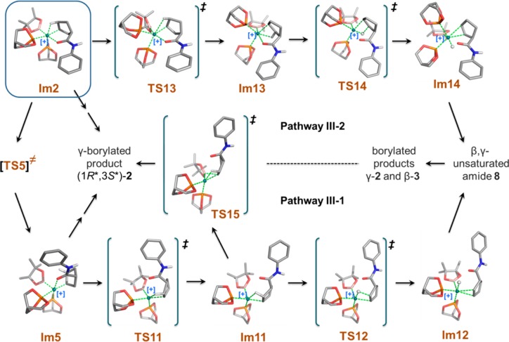
As summarized in Figure 1, we find, experimentally, that a small amount of the β-borylated compound 3 is generated as byproduct; its exact amount varies as a function of the exact nature of the catalyst and reaction conditions. In addition, experimental observations suggest that the cyclic β,γ-unsaturated amide 8, an isomer of the cyclic γ,δ-unsaturated amide substrate 1, is also transiently present in the reaction mixture (Figure 9). We reasoned that the β-borylated product 3 could be formed via rhodium-catalyzed hydroboration of the β,γ-unsaturated amide 8, the latter obtained by rhodium-catalyzed isomerization of the γ,δ-isomer 1. Two possible isomerization pathways providing a route to the β-borylated product (i.e., pathways III-1 and III-2) were identified in our computational study. Figure 10 shows the structures for all the intermediates, transition states, and the β,γ-unsaturated amide 8 in these potentially competitive pathways.
Figure 9.
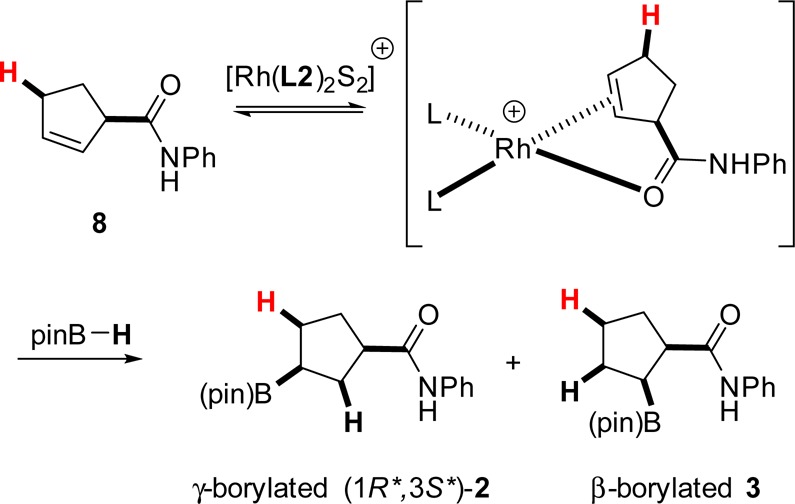
β- and γ-Borylated product formation starting with the β,γ-unsaturated amide. (Hydrogen atoms highlighted in red indicate expected incorporation from pinB–H.).
Figure 10.
Optimized structures involved in competing reaction pathways III-1 and III-2.
Figure 5 shows that the Rh, Cγ, Cβ, and Hβ atoms in intermediate Im5 all reside approximately in the same plane as required for β-hydride elimination; however, the calculated distance between Rh and Hβ is too long (2.600 Å) for facile β-hydride elimination to proceed directly from Im5. In our calculations, we find a more favorable mode coupled with breaking the Rh—O interaction and leading to TS11 (pathway III-1). It shows an imaginary vibrational mode involving moving the C=O moiety away from Rh while simultaneously moving Cβ and Hβ up and closer to Rh. As shown in Tables 2–4, the Rh—O distance is 2.180 Å in Im5, 3.426 Å in TS11, and 4.096 Å in Im11, respectively. The agostic interaction, Rh—HβCβ in Im11, is very similar to that observed in Im2 (Rh—Hβ distance is 2.018 Å; Cβ—Hβ distance is 1.163 Å). Cγ, Cβ, Hβ, and Rh remain nearly on the same plane in Im11. β-Hydride elimination occurs to form the double bond between Cγ and Cβ (see TS12 and Im12 in Figure 10). It should be noted that Im11 can also lead directly to the γ-borylated product 2 via a higher energy pathway TS15 (activation barrier of 17.4 kcal/mol).
Table 4. Selected Bond Lengths (Å) and Angles (deg) for Intermediates and Transition States in Pathway III.
| Rh–Cγ | Rh–Cβ | Cγ–Cβ | RhHβa | Rh–B | Rh–P1 | Rh–P2 | Rh–Ob | Cβ–Hβ | ObRhB | CγRhP1 | CγRhHβ | CγRhB | |
|---|---|---|---|---|---|---|---|---|---|---|---|---|---|
| TS11 | 2.114 | 2.514 | 1.516 | 2.090 | 2.043 | 2.406 | 2.197 | 3.426 | 1.138 | 88.07 | 155.71 | 63.58 | 111.04 |
| Im11 | 2.097 | 2.433 | 1.507 | 2.018 | 2.036 | 2.384 | 2.229 | 4.096 | 1.163 | 83.08 | 155.69 | 65.50 | 109.14 |
| TS12 | 2.257 | 2.337 | 1.409 | 1.629 | 2.036 | 2.285 | 2.368 | 1.738 | 157.37 | 83.03 | 111.22 | ||
| Im12 | 2.451 | 2.422 | 1.375 | 1.578 | 2.031 | 2.246 | 2.435 | 2.284 | 161.13 | 97.53 | 109.53 | ||
| TS13 | 2.147 | 2.963 | 1.556 | 2.943 | 2.076 | 2.202 | 2.203 | 2.345 | 1.095 | 159.43 | 134.88 | 49.42 | 74.80 |
| Im13 | 2.097 | 2.480 | 1.522 | 2.109 | 2.039 | 2.199 | 2.416 | 2.369 | 1.135 | 163.46 | 93.10 | 64.00 | 92.36 |
| TS14 | 2.248 | 2.293 | 1.417 | 1.616 | 2.043 | 2.345 | 2.308 | 2.385 | 1.683 | 167.84 | 90.41 | 82.85 | 90.08 |
| Im14 | 2.490 | 2.395 | 1.373 | 1.576 | 2.044 | 2.418 | 2.253 | 2.357 | 2.374 | 166.74 | 82.14 | 101.08 | 89.13 |
| TS15 | 2.190 | 2.419 | 1.538 | 2.035 | 2.087 | 2.329 | 2.204 | 4.082 | 1.147 | 95.98 | 158.61 | 64.38 | 58.96 |
RhHβ denotes the distance of Rh to Hβ;
O denotes the carbonyl oxygen atom of the substrate.
We considered another possible pathway (III-2) for the competing reaction based on intermediate Im2 involving Rh–Cγ bond rotation with TS13 as the rotation transition state. As listed in Table 4, the bond angle Cγ–Rh–P1 is 164.57° in Im2, 134.88° in TS13, and 93.10° in Im13, respectively. Rh and HβCβ are brought into close proximity by the Rh–Cγ bond rotation forming a Rh–HβCβ agostic interaction trans to a phosphite ligand (i.e., P1) as seen in intermediate Im13; the calculated agostic interaction is similar to that found in other intermediates (Rh–Hβ distance is 2.109 Å; Cβ–Hβ distance is 1.135 Å). β-Hydride elimination leads to the coordinated β,γ-unsaturated intermediate Im14 (Figure 10).
Figure 11 shows a comparison of the free-energy profiles for III-1 and III-2, and geometric parameters for the calculated intermediates and transitions states are summarized in Table 4. Pathway III-1 is the more favorable pathway to the β,γ-unsaturated intermediate 8 and ultimately the minor β-borylated product 3. The calculated barrier to Rh–Cγ bond rotation in pathway III-2 is approximately 17.9 kcal/mol higher in energy than breaking the Rh–O interaction in pathway III-1 (Figure 11). The activation barrier from Im5 to TS11 is even slightly lower than that of the reductive elimination step of pathway I-2 (i.e., Im5 to TS6), and the barrier to β-hydride elimination (i.e., Im11 to TS12, the reverse reaction of Rh–H migratory insertion) is also very low.
Figure 11.
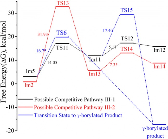
Comparison of the potential energy profiles for pathways III-1 and III-2.
Pathway III-1 is very competitive to pathway I-2 in this model reaction, perhaps accounting for the observed formation of byproduct 3 in the experimental studies. Although the requisite calculations have not been carried out as part of this study, once formed, the β,γ-unsaturated intermediate 8 can in principle undergo rhodium-catalyzed hydroboration to form either of the regioisomeric β- or γ-borylated products (Figure 9); the ratio is expected to vary as a function of the precise reaction conditions, especially the nature of the ligand and borane employed. In support of this conjecture, we find that under conditions similar to those described in Figure 1, an independently prepared β,γ-unsaturated substrate 8 gave a mixture of β-borylated (20%) and γ-borylated (51%) products.
Conclusions
Using density functional theory calculations, we studied the mechanism of the rhodium-catalyzed hydroboration of a cyclic γ,δ-unsaturated amide 1 using a cationic rhodium(I) complex featuring two-point binding of the substrate. Our computational studies assume that norbornadiene (nbd), which accompanies the rhodium catalyst precursor used in the experimental work that motivated this study, is not involved in the active catalyst.76,77 The main characteristics of the two-point binding mechanism are as follows. (1) The substrate has two coordinating groups, the alkene and amide carbonyl oxygen, that can chelate the substrate to the cationic Rh(I) catalyst leading to the predicted cis relative configuration for the major γ-borylated product (1R*,3S*)-2. The computational results are supported by experimental results obtained for the related directed CAHB of the same substrate leading to cis-(1R,3S)-2 as the major product. (2) The overall catalytic cycle for a model reaction using caged phosphite ligands leading to the major γ-borylated product (1R*,3S*)-2 includes the following steps: (i) chelation of the cyclic γ,δ-unsaturated amide substrate 1 to the active catalytic species [Rh(L2)2S2]+, (ii) oxidative addition of pinBH to rhodium, (iii) preferred migratory insertion of the coordinated alkene into the Rh–H, rather than Rh–B, bond to form C–H and Rh–C bonds, (iv) isomerization (amide rotation) of the resulting intermediate, and (v) reductive elimination to form the B–C bond and regenerate the catalyst. (3) Of the potential pathways to the β-borylated product considered, the amide rotation pathway (pathway I-2) is calculated to be the most favorable. (4) The amide rotation can, however, also divert to an accessible β-hydride elimination pathway accounting for the competing formation of some β-borylated product 3. (5) Finally, compared to previously explored one-point binding mechanisms for rhodium-catalyzed hydroborations, the two-point binding mechanism can better rationalize experiment observations for the desymmetrization reactions of cyclic γ,δ-unsaturated amides and the enantioselective reactions of acyclic di- and trisubstituted β,γ-unsaturated amides via CAHB.
Acknowledgments
We gratefully acknowledge financial support from the NIH (GM100101). Computational work was partially done using the computer facility in the Holland Computing Center at University of Nebraska. We thank S. M. Smith, L. S. W. Pelter, and M. Pelter for preliminary studies in the early stages of this project.
Supporting Information Available
Relative energies before correction and relative free energies after correction according to formula 1 (Table S-1), Cartesian coordinates of all studied intermediates and transition states calculated using the 6-31+G**/LANL2DZ basis set using B3LYP functional with DFT, and experimental data for Figure 1. This material is available free of charge via the Internet at http://pubs.acs.org.
The authors declare no competing financial interest.
Funding Statement
National Institutes of Health, United States
Supplementary Material
References
- Jana R.; Pathak T. P.; Sigman M. S. Chem. Rev. 2011, 111, 1417–1492. [DOI] [PMC free article] [PubMed] [Google Scholar]
- Yang Y.; Buchwald S. L. J. Am. Chem. Soc. 2013, 135, 10642–10645. [DOI] [PMC free article] [PubMed] [Google Scholar]
- Smith K.; Elliot M. C.; Jones D. H. J. Org. Chem. 2013, 78, 9526–9531. [DOI] [PMC free article] [PubMed] [Google Scholar]
- Molander G. A.; Ryu D.; Hosseini-Sarvari M.; Devulapally R.; Seapy D. G. J. Org. Chem. 2013, 78, 6648–6656. [DOI] [PMC free article] [PubMed] [Google Scholar]
- Colombel V.; Rombouts F.; Oehlrich D.; Molander G. A. J. Org. Chem. 2012, 77, 2966–2970. [DOI] [PMC free article] [PubMed] [Google Scholar]
- Glasspoole B. W.; Ghozati K.; Moir J. W.; Crudden C. M. Chem. Commun. 2012, 48, 1230–1232. [DOI] [PubMed] [Google Scholar]
- Farmer J. L.; Hunter H. N.; Organ M. G. J. Am. Chem. Soc. 2012, 134, 17470–17473. [DOI] [PubMed] [Google Scholar]
- Lloyd G. C.; Lennox A. J. J. Angew. Chem., Int. Ed. 2012, 51, 9385–9388. [DOI] [PubMed] [Google Scholar]
- Tian P.; Dong H.; Lin G. ACS Catal. 2012, 2, 95–119. [Google Scholar]
- Cazorla C.; Métay E.; Lemaire M. Tetrahedron 2011, 67, 8615–8621. [Google Scholar]
- Crudden C. M.; Glasspoole B. W.; Lata C. J. Chem. Commun. 2009, 6704–6716and references cited therein. [DOI] [PubMed] [Google Scholar]
- Imao D.; Glasspoole B. W.; Laberge V. S.; Crudden C. M. J. Am. Chem. Soc. 2009, 131, 5024–5025. [DOI] [PubMed] [Google Scholar]
- Chen A.; Ren L.; Crudden C. M. J. Org. Chem. 1999, 64, 9704–9710. [Google Scholar]
- Le H.; Kyne R. E.; Brozek L. A.; Morken J. P. Org. Lett. 2013, 15, 1432–1435. [DOI] [PMC free article] [PubMed] [Google Scholar]
- Mlynarski S. N.; Karns A. S.; Morken J. P. J. Am. Chem. Soc. 2012, 134, 16449–16451. [DOI] [PMC free article] [PubMed] [Google Scholar]
- Zhang C.; Yun J. Org. Lett. 2013, 15, 3416–3419. [DOI] [PubMed] [Google Scholar]
- Matsuda N.; Hirano K.; Satoh T.; Miura M. J. Am. Chem. Soc. 2013, 135, 4934–4937. [DOI] [PubMed] [Google Scholar]
- Partridge B. M.; Chausset-Boissarie L.; Burns M.; Pulis A. P.; Aggarwal V. K. Angew. Chem., Int. Ed. 2012, 51, 11795–11799. [DOI] [PubMed] [Google Scholar]
- Larouche-Gauthier R.; Fletcher C. J.; Couto I.; Aggarwal V. K. Chem. Commun. 2011, 47, 12592–12594. [DOI] [PubMed] [Google Scholar]
- Ros A.; Aggarwal V. Angew. Chem., Int. Ed. 2009, 48, 6289–6292. [DOI] [PubMed] [Google Scholar]
- Molander G. A.; Wisniewski S. R. J. Am. Chem. Soc. 2012, 134, 16856–16868. [DOI] [PMC free article] [PubMed] [Google Scholar]
- Sandrock D. L.; Jean-Gérard L.; Chen C.; Dreher S. D.; Molander G. A. J. Am. Chem. Soc. 2010, 132, 17108–17110. [DOI] [PMC free article] [PubMed] [Google Scholar]
- Molander G. A.; Shin I.; Jean-Gérard L. Org. Lett. 2010, 12, 4384–4387. [DOI] [PMC free article] [PubMed] [Google Scholar]
- Awano T.; Ohmura T.; Suginome M. J. Am. Chem. Soc. 2011, 133, 20738–20741. [DOI] [PubMed] [Google Scholar]
- Ohmura T.; Awano T.; Suginome M. J. Am. Chem. Soc. 2010, 132, 13191–13193. [DOI] [PubMed] [Google Scholar]
- Feng X.; Jeon H.; Yun J. Angew. Chem., Int. Ed. 2013, 52, 3989–3992. [DOI] [PubMed] [Google Scholar]
- Zhang L.; Peng D.; Leng X.; Huang Z. Angew. Chem., Int. Ed. 2013, 52, 3676–3680. [DOI] [PubMed] [Google Scholar]
- Obligacion J. V.; Chirik P. J. Org. Lett. 2013, 15, 2680–2683. [DOI] [PubMed] [Google Scholar]
- Moure A. L.; Mauleón P.; Arrayás R. G.; Carretero J. C. Org. Lett. 2013, 15, 2054–2057. [DOI] [PubMed] [Google Scholar]
- Semba K.; Shinomiya M.; Fujihara T.; Terao J.; Tsuji Y. Chem.—Eur. J. 2013, 19, 7125–7132. [DOI] [PubMed] [Google Scholar]
- Semba K.; Fujihara T.; Terao J.; Tsuji Y. Chem.—Eur. J. 2012, 18, 4179–4184. [DOI] [PubMed] [Google Scholar]
- Gunanathan C.; Hölscher M.; Pan F.; Leitner W. J. Am. Chem. Soc. 2012, 134, 14349–14352. [DOI] [PubMed] [Google Scholar]
- Park J. K.; Ondrusek B. A.; McQuade D. T. Org. Lett. 2012, 14, 4790–4793. [DOI] [PubMed] [Google Scholar]
- Moteki S.; Toyama K.; Liu Z.; Ma J.; Holmes A. E.; Takacs J. M. Chem. Commun. 2012, 48, 263–265. [DOI] [PubMed] [Google Scholar]
- Männig D.; Nöth H. Angew. Chem., Int. Ed. Engl. 1985, 24, 878–879. [Google Scholar]
- Hayashi T.; Matsumoto Y.; Ito Y. J. Am. Chem. Soc. 1989, 111, 3426–3428. [Google Scholar]
- Evans D. A.; Fu G. C.; Hoveyda A. H. J. Am. Chem. Soc. 1992, 114, 6671–6679. [Google Scholar]
- Geier M. J.; Vogels C. M.; Decken A.; Westcott S. A. J. Organomet. Chem. 2009, 694, 3154–3159. [Google Scholar]
- Crudden C. M.; Edwards D. Eur. J. Org. Chem. 2003, 4695–4712. [Google Scholar]
- Crudden C. M.; Hleba Y. B.; Chen A. C. J. Am. Chem. Soc. 2004, 126, 9200–9201. [DOI] [PubMed] [Google Scholar]
- Neilson B. M.; Bielawski C. W. Organometallics 2013, 32, 3121–3128. [Google Scholar]
- Smith S. M.; Thacker N. C.; Takacs J. M. J. Am. Chem. Soc. 2008, 130, 3734–3735. [DOI] [PubMed] [Google Scholar]
- Smith S. M.; Takacs J. M. J. Am. Chem. Soc. 2010, 132, 1740–1741. [DOI] [PMC free article] [PubMed] [Google Scholar]
- Smith S. M.; Takacs J. M. Org. Lett. 2010, 12, 4612–4615. [DOI] [PMC free article] [PubMed] [Google Scholar]
- Smith S. M.; Uteuliyev M.; Takacs J. M. Chem. Commun. 2011, 47, 7812–7814. [DOI] [PubMed] [Google Scholar]
- Smith S. M.; Hoang G. L.; Pal R.; Bani Khaled M. O.; Pelter L. S. W.; Zeng X. C.; Takacs J. M. Chem. Commun. 2012, 48, 12180–12182. [DOI] [PMC free article] [PubMed] [Google Scholar]
- Lata C. J.; Crudden C. M. J. Am. Chem. Soc. 2010, 132, 131–137. [DOI] [PubMed] [Google Scholar]
- Evans D. A.; Fu G. C.; Anderson B. A. J. Am. Chem. Soc. 1992, 114, 6679–6685. [Google Scholar]
- K. Burgess K.; van der Donk W. A.; Westcott S. A.; Marder T. B.; Baker R. T.; Calabrese J. C. J. Am. Chem. Soc. 1992, 114, 9350–9359. [Google Scholar]
- Widauer C.; Grtzmacher H.; Ziegler T. Organometallics 2000, 19, 2097–2107. [Google Scholar]
- Dorigo A. E.; Schleyer P. v. R. Angew. Chem., Int. Ed. Engl. 1995, 34, 115–118. [Google Scholar]
- Musaev D. G.; Mebel A. M.; Morokuma K. J. Am. Chem. Soc. 1994, 116, 10693–10702. [Google Scholar]
- Daura-Oller E.; Segarra A. M.; Poblet J. M.; Claver C.; Fernández E.; Bo C. J. Org. Chem. 2004, 69, 2669–2680. [DOI] [PubMed] [Google Scholar]
- Segarra A. M.; Daura-Oller E.; Claver C.; Poblet J. M.; Bo C.; Fernández E. Chem.—Eur. J. 2004, 10, 6456–6467. [DOI] [PubMed] [Google Scholar]
- Landis C. R.; Halpern J. J. Am. Chem. Soc. 1987, 109, 1746–1754. [Google Scholar]
- Gridnev I. D.; Imamoto T. Chem. Commun. 2009, 45, 7447–7464. [DOI] [PubMed] [Google Scholar]
- Unpublished results; manuscript in preparation.
- Beeke A. D. J. Chem. Phys. 1993, 98, 5648–5652. [Google Scholar]
- Lee C.; Yang W.; Parr R. G. Phys. Rev. B. 1988, 37, 785–789. [DOI] [PubMed] [Google Scholar]
- Frisch M. J.; Trucks G. W.; Schlegel H. B.; Scuseria G. E.; Robb M. A.; Cheeseman J. R.; Scalmani G.; Barone V.; Mennucci B.; Petersson G. A.; Nakatsuji H.; Caricato M.; Li X.; Hratchian H. P.: Izmaylov A. F.; Bloino J.; Zheng G.; Sonnenberg J. L.; Hada M.; Ehara M.; Toyota K.; Fukuda R.; Hasegawa J.; Ishida M.; Nakajima T.; Honda Y.; Kitao O.; Nakai H.; Vreven T.; Montgomery J. A. Jr.; Peralta J. E.; Ogliaro F.; Bearpark M.; Heyd J. J.; Brothers E.; Kudin K. N.; Staroverov V. N.; Kobayashi R.; Normand J.; Raghavachari K.; Rendell A.; Burant J. C.; Iyengar S. S.; Tomasi J.; Cossi M.; Rega N.; Millam J. M.; Klene M.; Knox J. E.; Cross J. B.; Bakken V.; Adamo C.; Jaramillo J.; Gomperts R.; Stratmann R. E.; Yazyev O.; Austin A. J.; Cammi R.; Pomelli C.; Ochterski J. W.; Martin R. L.; Morokuma K.; Zakrzewski V. G.; Voth G. A.; Salvador P.; Dannenberg J. J.; Dapprich S.; Daniels A. D.; Farkas O.; Foresman J. B.; Ortiz J. V.; Cioslowski J.; Fox D. J.. Gaussian, Inc., Wallingford, CT, 2009. [Google Scholar]
- Fukui K. Acc. Chem. Res. 1981, 14, 363–368. [Google Scholar]
- For those unfamiliar with the convention for denoting the relative but not the absolute configuration, see:Cross L. C.; W. Klyne W. Pure Appl. Chem. 1976, 45, 11–30. [Google Scholar]
- Tamura H.; Yamazaki H.; Sato H.; Sakaki S. J. Am. Chem. Soc. 2003, 125, 16114–16126. [DOI] [PubMed] [Google Scholar]
- Sakaki S.; Takayama T.; Sumimoto M.; Sugimoto M. J. Am. Chem. Soc. 2004, 126, 3332–3348. [DOI] [PubMed] [Google Scholar]
- Preliminary attempts to calculate transitions states for alkene insertion into the more distal basal, rather than the proximal apical, Rh–H (or Rh–B) bond were unsuccessful and suggest that the pathway is significantly higher in energy.
- Baker R. T.; Calabrese J. C.; Westcott S. A.; Nguyen P.; Marder T. B. J. Am. Chem. Soc. 1993, 115, 4367–4368. [Google Scholar]
- Westcott S. A.; Marder T. B.; Baker R. T. Organometallics 1993, 12, 975–979. [Google Scholar]
- Coapes R. B.; Souza F. E. S.; Thomas R. L.; Hall J. J.; Marder T. B. Chem. Commun. 2003, 614–615. [DOI] [PubMed] [Google Scholar]
- Mkhalid I. A. I.; Coapes R. B.; Edes S. N.; Coventry D. N.; Souza F. E. S.; Thomas R. LI.; Hall J. J.; Bi S.-W.; Lin Z.; Marder T. B. Dalton Trans. 2008, 1055–1064. [DOI] [PubMed] [Google Scholar]
- Zhu J.; Lin Z.; Marder T. B. Inorg. Chem. 2005, 44, 9384–9390. [DOI] [PubMed] [Google Scholar]
- Dang L.; Lin Z.; Marder T. B. Chem. Commun. 2009, 3987–3995. [DOI] [PubMed] [Google Scholar]
- Irvine G. J.; Lesley M. J. G.; Marder T. B.; Norman N. C.; Rice C. R.; Robins E. G.; Roper W. R.; Whittell G. R.; Wright L. J. Chem. Rev. 1998, 98, 2685–2722. [DOI] [PubMed] [Google Scholar]
- Pubill-Ulldemolins C.; Poyatos M.; Bo C.; Fernández E. Dalton Trans. 2013, 42, 746–752. [DOI] [PubMed] [Google Scholar]
- We looked for experimental evidence for the dehydrogenative borylation pathway, specifically formation of the expected allylic alcohol (and the potential vinylborane-derived ketone), and found no evidence for their formation.
- Although racemic tmdBH is used in the CAHB shown in Figure 1, it has been found in prior studies that the chirality of tmdBH is inconsequential to the stereochemistry of reaction; see ref (45).
- In support of this assumption, we find that (1) norbornene is a substrate for hydroboration by the catalyst used experimentally, and (2) the experimental results are essentially unchanged using the corresponding Rh(cod)2BF4 catalyst precursor.
- In contrast, it can be noted that coordinated cyclooctadiene resists iridium-catalyzed hydroboration by catecholborane; see:Nguyen P.; Blom H. P.; Westcott S. A.; Taylor N. J.; Marder T. B. J. Am. Chem. Soc. 1993, 115, 9329–9330. [Google Scholar]
Associated Data
This section collects any data citations, data availability statements, or supplementary materials included in this article.


