

Abstract
Coarse-grained (CG) and multiscale simulations are widely used to study large biological systems. However, preparing the simulation system is time-consuming when the system has multiple components, because each component must be arranged carefully as in protein/micelle or protein/bilayer systems. We have developed CHARMM-GUI PACE CG Builder for building solution, micelle, and bilayer systems using the PACE force field, a united-atom (UA) model for proteins, and the Martini CG force field for water, ions, and lipids. The robustness of PACE CG Builder is validated by simulations of various systems in solution (α3D, fibronectin, and lysozyme), micelles (Pf1, DAP12-NKG2C, OmpA, and DHPC-only micelle), and bilayers (GpA, OmpA, VDAC, MscL, OmpF, and lipid-only bilayers for six lipids). The micelle’s radius of gyration, the bilayer thickness, and the per-lipid area in bilayers are comparable to the values from previous all-atom and CG simulations. Most tested proteins have root-mean squared deviations of less than 3 Å. We expect PACE CG Builder to be a useful tool for modeling/refining large, complex biological systems at the mixed UA/CG level.
Introduction
Molecular dynamics (MD) simulations are widely used to study biological systems that consist of protein, nucleic acids, lipids, and glycans. When the system size becomes intractable for all-atom simulation, coarse-grained (CG) and multiscale simulations are commonly used to average out some degrees of freedom in the system. Despite the paucity in molecular detail, CG simulations provide valuable information for understanding biological processes such as protein assembly,1−3 protein–protein interactions,4,5 protein folding,6,7 and membrane reactions.8−10 Moreover, incorporation of experimental data from methods such as FRET,11 cryoEM,12 and SAXS,13 greatly extends the capability of CG models to describe complex biological systems.
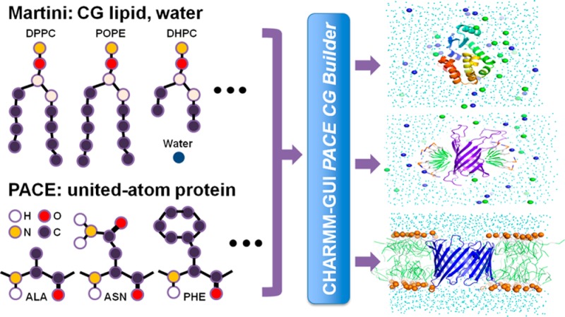
One popular CG force field (FF), known as Martini,14 maps on average four heavy atoms along with respective hydrogen atoms to one CG particle. The CG particles are classified into four main types—polar, nonpolar, apolar, and charged—and each main type is further classified based on its hydrogen-bonding capability or degree of polarity. The Martini FF was originally developed for lipids and later extended to include sugars15 and protein.16 However, the application of the Martini protein is limited to cases where details of conformational features are of little significance. Therefore, it is desirable to develop a hybrid model that accounts for proteins to a degree of detail necessary for a CG description. One recent hybrid model of such kind is the PACE FF,17−19 which represents explicitly protein heavy atoms and polar hydrogen atoms (i.e., employs a united atom model). The PACE FF was parametrized in conjunction with Martini water and lipid, and it was shown to be able to fold small peptides and proteins and reproduce a variety of experimental observations.19
Although a combination of the Martini and PACE FFs holds great promise for simulations of proteins in heterogeneous environments, it is not trivial to construct heterogeneous systems for such simulations in a user-friendly manner. We note that there are scripts to generate Martini CG bilayers (http://md.chem.rug.nl/cgmartini/index.php/tools2) and PACE hybrid systems,19 but both scripts involve several programs. When a system has multiple components or involves a special arrangement (e.g., a micelle), using these scripts is challenging. While there are web-based user interfaces to build atomistic simulation systems,20−25 to the best of our knowledge, no such tool is available for the Martini/PACE hybrid model.
Here, we report the development of a web interface, CHARMM-GUI PACE CG Builder (http://www.charmm-gui.org/input/cgbilayer for bilayer builder), to simplify the building of multiscale systems for PACE and Martini FF simulations in solution, micelle, and bilayer. We examined various simulation systems to demonstrate that PACE CG Builder is robust and that the software is well-suited for various types of simulations.
Methods
Software Requirements
For lipid-only systems, NAMD 2.10 or a nightly build version is required to calculate the Martini Lennard-Jones switching energy correctly. For protein–lipid system, a modified version of NAMD is needed to deal with the nonbonded potentials designed for the PACE FF. This version of NAMD is available at the PACE CG Bilayer Builder front page (http://www.charmm-gui.org/input/cgbilayer).
PACE CG Builder
PACE CG Builder in CHARMM-GUI provides a separate submenu for Solution Builder, Micelle Builder, and Bilayer Builder. The overall processes of building solution, micelle, and bilayer CG simulation systems are identical to the corresponding all-atom builders (i.e., Quick MD Simulator,(21)Membrane Builder,(20,23) and Micelle Builder(25)). Briefly, for PACE CG Bilayer Builder, a user can build a protein/bilayer complex or a bilayer-only system with single or multiple lipid types (see Figure 1 for the overall building process and Supporting Information Figures S1–3 for the screenshots of the web interface). Building and simulating the systems involve seven steps. In step 1, in the case of a protein/bilayer complex system, the protein structure can be read-in either from user input or the PDB26/OPM database;27 we note that the PDB structure from OPM is preoriented along the Z-axis, i.e., along the membrane normal, with the bilayer center at Z = 0. In step 2, the protein can be oriented if not aligned properly and pore water molecules can be added if necessary. In step 3, the system size is determined and the head groups of the lipids are packed using lipid-like pseudo atoms as described in detail in previous works20,23,25 (check step3_packing.pdb for lipid packing around a protein). The bilayer-only system building starts from step 3. In step 4, each component, such as water, ions, and lipids, is built separately. In step 5, all components previously built in step 4 are assembled, and the restraint and configuration files for NAMD are generated for equilibration (step 6) and production (step 7). Because the protein in the PACE FF has not been parametrized with phosphatidylglycerol (PG) and phosphatidylserine (PS) lipid types, only phosphatidylcholine (PC) and phosphatidylethanolamine (PE) lipid types are currently supported for protein/bilayer systems (see Table 1 for available PC and PE lipid types), and available ion types are limited to Na+ and Cl–.
Figure 1.

Procedure of system setup using PACE CG Micelle and Bilayer Builders.
Table 1. Lipid and Detergent Types Available in PACE CG Builder.
| name | full name | initial surface area (Å2)a |
|---|---|---|
| DLPC | dilauroyl-phosphatidylcholine | 57.2 |
| DPPC | dipalmitoyl-phosphatidylcholine | 63 |
| DSPC | distearoyl-phosphatidylcholine | 63 |
| POPC | palmitoyl-oleoyl-phosphatidylcholine | 68.3 |
| DOPC | dioleoyl-phosphatidylcholine | 67.4 |
| DAPC | diarachidoyl-glycerophosphocholine | 75 |
| DLPE | dilauroyl-phosphatidylethanolamine | 55 |
| DPPE | dipalmitoy-phosphatidylethanolamine | 63 |
| DSPE | distearoyl-phosphatidylethanolamine | 63 |
| POPE | palmitoyl-oleoyl-phosphatidylethanolamine | 63 |
| DOPE | dioleoyl-phosphatidylethanolamine | 67.4 |
| DHPC | diheptanoyl-phosphatidylcholine | 50 |
The initial surface area is used to estimate the number of lipids in bilayer and micelle system building. Data from ref (23).
For PACE CG Micelle Builder, all the building steps are similar to PACE CG Bilayer Builder except that detergents are used instead of lipids. Currently, only diheptanoyl-phosphatidylcholine (DHPC) is supported as a detergent. For PACE CG Solution Builder, the protein is solvated in step 2, and the periodic boundary condition is setup in step 3. NAMD inputs for equilibration (step 4) and production (step 5) are provided. The simulation protocol including the nonbonded interaction options is described below in detail.
The CHARMM28 scripts for building the systems and the NAMD input files for equilibration and production are available to users. The CHARMM input files for simulations are not provided currently because the PACE FF uses 1–2 and 1–4 nonbonded interaction schemes at the same time, which is not implemented in CHARMM.
Test Systems
The PDB IDs of all the proteins used in this work are 2A3D (α3D: a de novo designed single-chain three-helix bundle);292KBG (Fibronectin: the second Fibronectin type-III module of NCAM2); 2LZM (bacteriophage T4 lysozyme);302KSJ (Pf1 coat protein: the major coat protein of Pf1 bacteriophage);312L35 (the DAP12-NKG2C transmembrane heterotrimer);321G90 (OmpA: outer membrane protein A);331AFO (GpA: dimeric transmembrane domain of human glycophorin A);342K4T (VDAC: the voltage-dependent anion channel);352OAR (MscL: mechanosensitive channel of large conductance);36 and 2OMF (OmpF: outer membrane protein F). In DAP12-NKG2C, the aspartate residue (Asp16) in one of the DAP12 protomers, which faces out toward the bilayer hydrophobic core, was protonated, as in a previous study.37 In GpA, only the transmembrane part was simulated with a sequence of Ace-ITLIIFGVMAGVIGTILLISYGI-NMe. The starting structures used in bilayer and micelle simulations were obtained from the OPM database.27 All the systems were first neutralized with Na+ and Cl– ions and buffered with 0.15 M NaCl solution. For solution and micelle systems, the system size was determined by extending 15 Å from each side of the protein in the X, Y, and Z direction. In bilayer systems, the system size in the XY plane was determined to match the area of lipids and proteins, and a 15 Å water layer was added to each side of the bilayer.
Lipid Library
To sample the lipid structures effectively in the building process of a bilayer system, we used a lipid library that consists of 2000 configurations for each lipid type (Table 1), selected from a 100-ns simulation of a CG lipid bilayer. The bilayer system was simulated at 300 K with the presence of five molecules of each lipid type in each leaflet (one of the lipid layers). The frequency of saving the trajectory was 100 ps. After the principle geometric axis of each configuration was aligned to the Z-axis, the configurations with the first 2000 smallest radius of gyration on the XY plane were selected for the lipid library.
Simulation Protocol
For all micelle and bilayer systems, PACE CG Builder provides NAMD input files for the CHARMM-GUI standard six equilibration steps, during which the restraints on the lipid/detergent head groups and protein atoms are gradually reduced. As bilayers and micelles are modeled with MARTINI, calculation of nonbonded interactions for these systems follows a 1–2 rule, namely that nonbonded interactions are excluded if two interacting particles are separated at most by one bond. As for protein systems modeled with PACE, a 1–4 rule is applied to the calculation of nonbonded interactions. Thus, both rules are needed for systems with proteins in bilayers or micelles, which have been implemented in the modified NAMD as discussed above. For all systems, the electrostatic potential was evaluated by applying a shifting function between 0 and 12 Å. The dielectric constant was set to 15, the value used in PACE and MARTINI simulations. The nonbonded van der Waals interactions were calculated with a switching distance over 9–12 Å. The distance cutoff for searching for lists of interacting pairs was set to 14 Å. The time step was 20 fs for lipid-only systems38 and 5 fs for protein-involved systems.19 All simulations here were performed in the NPT (constant number of particle, pressure, and temperature) ensemble. Temperature was controlled at 300 K with Langevin dynamics using a damping coefficient of 1 ps; pressure was controlled at 1.01325 bar with the Langevin piston Nose–Hoover method.39,40
Trajectory Analysis
In lipid-only bilayer systems, the area per lipid was calculated by dividing the area in the XY plane by the number of lipids in one leaflet. The bilayer thickness was the distance between the average Z positions of the phosphate groups in each leaflet. The radius of gyration of micelle-containing systems was calculated with respect to phosphate atoms of detergent molecules. Root-mean squared deviation (RMSD) was calculated with respect to Cα atoms in helices and β strands; in cases of membrane proteins, RMSD of their transmembrane part was evaluated. Trajectory analyses were performed using tools from CHARMM28 and VMD.41
Results and Discussion
In this section, we first validate that the Martini FF in the CHARMM format used in PACE CG Builder is accurate compared to the original FF in the Gromacs format. Then, the simulation results for 18 solution, micelle, and bilayer systems are presented and discussed in terms of RMSD, root-mean squared fluctuation (RMSF), radius of gyration, bilayer thickness, and per-lipid area.
Energy Comparison of Lipid-Only Bilayer Systems
As the Martini FF was originally developed in the framework of the simulation software package Gromacs,42 we converted the Martini FF to the CHARMM format to be used in the CHARMM-GUI framework. To validate the conversion, we compared the potential energies calculated using NAMD and Gromacs 4.5.542 for one DHPC micelle and three lipid-only bilayer systems (Supporting Information Table S1). For these systems, the differences in bond, angle, van der Waals, and electrostatic energies from NAMD and Gromacs are very small, with a relative deviation of no more than 1.9 × 10⁻⁶. The results demonstrate that the converted Martini FF is accurate enough to be used with NAMD to model systems with detergent/lipid as it is in Gromacs.
Simulation Examples of Solution, Micelle, and Bilayer Systems
To test PACE CG Builder and verify that the generated system and simulation files work properly, we performed 100-ns simulations of various solution, micelle, and bilayer systems with the number of atoms varying from ∼2500 to ∼16 500 (Table 2). For solution systems, the tested proteins are: α3D (a small designed three-helix bundle protein),29 fibronectin (a protein with all-β structure), and lysozyme (a protein that is mostly helical).30 The small RMSD (<∼3 Å) observed during the course of the 100-ns simulations indicates that the native structures of α3D and fibronectin are well-maintained through the approach introduced in the current study (Figure 2). The lysozyme protein, however, is more flexible, reaching a RMSD of ∼4 Å at the end of the 100-ns simulation. Visual inspection revealed that the conformational change corresponding to the maximal RMSD (∼5 Å) involves the displacements of the helices from the amino- and carboxy-terminal domains (Supporting Information Figure S4). Such a change is consistent with the intrinsic hinge-bending motion of lysozyme in solution as seen in previous experiments.43,44
Table 2. Test Systems for the Solution, Micelle, and Bilayer Builders.
| builder | system | lipid number | system size (Å3) | no. atoms |
|---|---|---|---|---|
| solution | α3D | 0 | 63 × 63 × 63 | 2565 |
| solution | fibronectin | 0 | 74 × 74 × 74 | 4100 |
| solution | lysozyme | 0 | 81 × 81 × 81 | 5626 |
| micelle | DHPC | 35 | 70 × 70 × 70 | 2789 |
| micelle | Pf1 + DHPC | 75 | 83 × 83 × 83 | 5009 |
| micelle | DAP12-NKG2C + DHPC | 100 | 85 × 85 × 85 | 6029 |
| micelle | OmpA + DHPC | 80 | 87 × 87 × 87 | 6981 |
| bilayer | DLPE | 200 | 74 × 74 × 70 | 3290 |
| bilayer | DLPC | 200 | 75 × 75 × 70 | 3361 |
| bilayer | DPPC | 200 | 79 × 79 × 70 | 3647 |
| bilayer | POPE | 200 | 79 × 79 × 70 | 3896 |
| bilayer | POPC | 200 | 82 × 82 × 70 | 4027 |
| bilayer | DOPC | 200 | 82 × 82 × 70 | 4199 |
| bilayer | GpA + POPC | 160 | 74 × 74 × 83 | 4204 |
| bilayer | OmpA + DOPE | 200 | 87 × 87 × 93 | 7216 |
| bilayer | VDAC + POPC | 200 | 95 × 95 × 76 | 7614 |
| bilayer | MscL + POPE | 204 | 95 × 95 × 118 | 13222 |
| bilayer | OmpF + POPC | 226 | 112 × 112 × 88 | 16548 |
Figure 2.
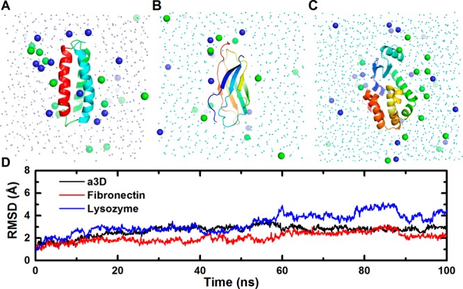
Solution systems of (A) α3D, (B) fibronectin, (C) lysozyme, and (D) their RMSD time-series. Sodium and chloride ions are in blue and green spheres.
To examine the capability of our approach for micelle systems, we tested four systems: a detergent-only system consisting of 65 DHPC; Pf1 (a coat protein from Pf1 bacteriophage);31 DAP12-NKG2C (the complex of the DAP12 signaling module and the natural killer cell-activating receptor NKG2C);32 OmpA (outer membrane protein A) (Figure 3).33 The radius of gyration (Rg) of the head groups in the DHPC micelle is 21.0 ± 0.3 Å, in agreement with the result of a previous all-atom simulation (21.4 ± 0.2 Å).25 In the protein systems, the Rg values did not fluctuate significantly, indicating overall stable protein/micelle complex structures. Pf1 and OmpA are very stable during the simulations, showing RMSD of less than 3 Å. To further evaluate if the simulations reproduce properly the interactions between proteins and their heterogeneous environments, we calculated the contact frequency of each residue in Pf1 to water, detergent head, and tail groups (Figure 4). The transmembrane helix has higher frequency to interact with detergent tail groups than the periplasmic helix, in agreement with a previous all-atom simulation.25 Compared to Pf1 and OmpA, DAP12-NKG2C shows larger fluctuations, with the largest RMSD approaching ∼5 Å. Comparison of the final structure from the simulation to the initial structure reveals that the DAP12 dimer is distorted and rotated (Supporting Information Figure S5). Possible causes of such rearrangement are the polar residues (Asp16, Thr20, and Lys52) at the DAP12-NKG2C interface.32 In the NMR structure, Lys52 forms an electrostatic network with Asp16 and Thr20 from one DAP12 protomer. However, during the simulation, Asp16 and Thr20 from the other DAP12 protomer move inward and distort the helix, which was also observed in all-atom simulations (data not shown).37
Figure 3.
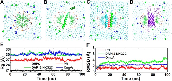
Micelle systems. (A) DHPC, (B) Pf1, (C) DAP12-NKG2C, (D) OmpA, (E) the time-series of radius of gyration of the detergent head groups, and (F) RMSD time-series of the proteins. Sodium and chloride ions are in blue and green spheres.
Figure 4.
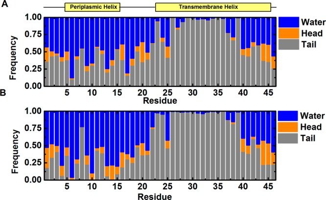
Contact frequency of residues in Pf1 to water, detergent head, and tail groups from (A) PACE CG and (B) all-atom simulations.25 A contact is counted when the distance of a protein heavy atom to water/detergent is less than 5.5 Å.
Finally, we extended our test to bilayer systems. We first tested six lipid-only bilayer systems, each consisting of 200 DLPC, DLPE, DPPC, POPC, POPE, and DOPC. The bilayer thickness and area per lipid of these systems did converge well (Table 3 and Supporting Information Figure S6). Moreover, the areas per lipid for all the systems are close to the results from previous CG simulations and experiments (Table 3). Five proteins, namely GpA, OmpA, VDAC, MscL, and OmpF, in different types of lipid bilayers were also tested. Except for GpA, the RMSDs of the proteins are smaller than 3 Å (Figure 5 and Supporting Information Figure S7). GpA has a slightly larger RMSD due to a 10° change in the crossing angle between the helices (Supporting Information Figure S8). In addition to protein stability, we also examined the dynamics of proteins in PACE CG simulations. Specifically, we analyzed the RMSF of VDAC for which the same analysis of all-atom simulations is available. As shown in Figure 5E, the RMSFs arising from the PACE CG and all-atom simulations are very similar, particularly for the regions where secondary structures are formed. Interestingly, the loop regions exhibit larger RMSF values for the CG simulation, suggesting that more conformational variations in these regions are sampled. As the PACE FF often leads to simulations with dynamics faster than those using all-atom FF by about 1 order of magnitude,19 our current 100-ns simulation may allow us to observe the dynamics that actually requires microsecond-long simulations in the all-atom case.
Table 3. Thickness and Area Per Lipid of Lipid-Only Bilayer Systemsa.
| area per lipid (Å2) |
||||
|---|---|---|---|---|
| lipid | thickness (Å) | current study | previous CG simulations46 | experiment |
| DLPC | 34.4 ± 0.3 | 60.1 ± 0.8 | 60 | 63 (303 K)47 |
| DLPE | 36.0 ± 0.3 | 55.3 ± 0.7 | 55 | 51 (308 K)48 |
| DPPC | 41.5 ± 0.4 | 60.2 ± 0.9 | 59 | |
| POPC | 42.6 ± 0.4 | 64.8 ± 0.9 | 64 (298 K)49 | |
| POPE | 44.1 ± 0.4 | 61.2 ± 0.8 | 59 | 57 (303 K)50 |
| DOPC | 44.2 ± 0.4 | 68.0 ± 0.9 | 67 | 72 (303 K)48 |
The current and previous CG simulations were all done at 300 K.
Figure 5.
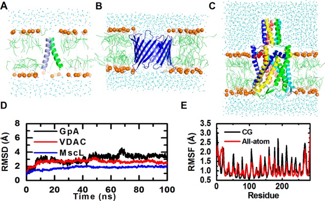
Bilayer systems. (A) GpA, (B) VDAC, (C) MscL, (D) their RMSD time-series, and (E) RMSF of VDAC from CG and a 65-ns all-atom simulation.51 Lipid phosphate atoms are in orange spheres. RMSF was calculated using the backbone non-hydrogen atoms.
Conclusion
In this study, we developed and tested the CHARMM-GUI PACE CG Builder, a web-based user interface for building solution, micelle, and bilayer PACE CG simulation systems. A total of 18 different systems were investigated in regard to structural stability during their simulations. Most proteins have RMSD values of less than 3 Å, and the radius of gyration, the bilayer thickness, and the area per lipid are similar to those from previous simulations. With the Martini CG FF, the number of atoms in a simulation system can be reduced by a factor of 10. Considering that a time step of 5 fs is used in the PACE/Martini hybrid simulation, about 30-times increase in simulation performance can be achieved compared to all-atom simulations using a 2-fs time step (Table 4). Finally, the PACE FF provides more details for the protein than the Martini protein model, which is a superior feature in applications such as structural refinement.45 We expect PACE CG Builder to be a useful tool for studying solution, micelle, and bilayer systems at the united-atom and CG level.
Table 4. Speed Comparison of PACE CG and All-Atom Simulationa.
| PACE CG |
All-atom |
||||||
|---|---|---|---|---|---|---|---|
| system | box size (Å3) | atom number | speed (ns/day) | box size (Å3) | atom number | speed (ns/day) | speed up |
| α3d | 63 × 63 × 63 | 2565 | 40.0 | 63 × 63 × 63 | 24702 | 1.4 | 28 |
| Pf1 | 83 × 83 × 83 | 5009 | 26.3 | 83 × 83 × 83 | 53753 | 0.7 | 37 |
| VDAC | 95 × 95 × 76 | 7614 | 17.2 | 95 × 95 × 76 | 65033 | 0.6 | 28 |
The all-atom systems were built to match the box size of the CG systems with the same number of lipids or detergents. Simulations were performed on a 2.83 GHz Intel Xeon CPU using four cores.
Acknowledgments
This work was supported in part by NSF ABI-1145987, NIH U54GM087519, and XSEDE TG-MCB070009 (to WI).
Supporting Information Available
Screenshots of the PACE CG builder web interface (Figures S1–3). Comparison of the last snapshot from MD to the crystal structure of lysozyme (Figure S4). Comparison of the last snapshot from MD to the NMR structure of DAP12-NKG2C (Figure S5). Thickness and area per lipid of bilayer systems (Figure S6). Structure and RMSD time-series of OmpA and OmpF in bilayer (Figure S7). The conformation of GpA during simulation (Figure S8). Validation of the converted MARTINI force field (Table S1). This material is available free of charge via the Internet at http://pubs.acs.org.
The authors declare no competing financial interest.
Funding Statement
National Institutes of Health, United States
Supplementary Material
References
- Arkhipov A.; Freddolino P. L.; Schulten K. Stability and Dynamics of Virus Capsids Described by Coarse-Grained Modeling. Structure 2006, 14, 1767–1777. [DOI] [PubMed] [Google Scholar]
- Nguyen H. D.; Reddy V. S.; Brooks C. L. 3rd Invariant Polymorphism in Virus Capsid Assembly. J. Am. Chem. Soc. 2009, 131, 2606–2614. [DOI] [PMC free article] [PubMed] [Google Scholar]
- Ayton G. S.; Voth G. A. Multiscale Computer Simulation of the Immature Hiv-1 Virion. Biophys. J. 2010, 99, 2757–2765. [DOI] [PMC free article] [PubMed] [Google Scholar]
- Hall B. A.; Armitage J. P.; Sansom M. S. Mechanism of Bacterial Signal Transduction Revealed by Molecular Dynamics of Tsr Dimers and Trimers of Dimers in Lipid Vesicles. PLoS Comput. Biol. 2012, 8, e1002685. [DOI] [PMC free article] [PubMed] [Google Scholar]
- Janosi L.; Li Z.; Hancock J. F.; Gorfe A. A. Organization, Dynamics, and Segregation of Ras Nanoclusters in Membrane Domains. Proc. Natl. Acad. Sci. USA 2012, 109, 8097–8102. [DOI] [PMC free article] [PubMed] [Google Scholar]
- Qi Y.; Huang Y.; Liang H.; Liu Z.; Lai L. Folding Simulations of a De Novo Designed Protein with a Betaalphabeta Fold. Biophys. J. 2010, 98, 321–329. [DOI] [PMC free article] [PubMed] [Google Scholar]
- Zhang Z.; Chan H. S. Competition between Native Topology and Nonnative Interactions in Simple and Complex Folding Kinetics of Natural and Designed Proteins. Proc. Natl. Acad. Sci. USA 2010, 107, 2920–2925. [DOI] [PMC free article] [PubMed] [Google Scholar]
- Marrink S. J.; de Vries A. H.; Tieleman D. P. Lipids on the Move: Simulations of Membrane Pores, Domains, Stalks and Curves. Biochim. Biophys. Acta 2009, 1788, 149–168. [DOI] [PubMed] [Google Scholar]
- Wu Z.; Cui Q.; Yethiraj A. Why Do Arginine and Lysine Organize Lipids Differently? Insights from Coarse-Grained and Atomistic Simulations. J. Phys. Chem. B 2013, 117, 12145–12156. [DOI] [PubMed] [Google Scholar]
- Yoo J.; Jackson M. B.; Cui Q. A Comparison of Coarse-Grained and Continuum Models for Membrane Bending in Lipid Bilayer Fusion Pores. Biophys. J. 2013, 104, 841–852. [DOI] [PMC free article] [PubMed] [Google Scholar]
- Marius P.; Leung Y. M.; Piggot T. J.; Khalid S.; Williamson P. T. Probing the Oligomeric State and Interaction Surfaces of Fukutin-I in Dilauroylphosphatidylcholine Bilayers. Eur. Biophys. J. 2012, 41, 199–207. [DOI] [PMC free article] [PubMed] [Google Scholar]
- Grubisic I.; Shokhirev M. N.; Orzechowski M.; Miyashita O.; Tama F. Biased Coarse-Grained Molecular Dynamics Simulation Approach for Flexible Fitting of X-Ray Structure into Cryo Electron Microscopy Maps. J. Struct. Biol. 2010, 169, 95–105. [DOI] [PubMed] [Google Scholar]
- Yang S.; Blachowicz L.; Makowski L.; Roux B. Multidomain Assembled States of Hck Tyrosine Kinase in Solution. Proc. Natl. Acad. Sci. USA 2010, 107, 15757–15762. [DOI] [PMC free article] [PubMed] [Google Scholar]
- Marrink S. J.; Risselada H. J.; Yefimov S.; Tieleman D. P.; de Vries A. H. The Martini Force Field: Coarse Grained Model for Biomolecular Simulations. J. Phys. Chem. B 2007, 111, 7812–7824. [DOI] [PubMed] [Google Scholar]
- López C. A.; Rzepiela A. J.; de Vries A. H.; Dijkhuizen L.; Hünenberger P. H.; Marrink S. J. Martini Coarse-Grained Force Field: Extension to Carbohydrates. J. Chem. Theory Comput. 2009, 5, 3195–3210. [DOI] [PubMed] [Google Scholar]
- Monticelli L.; Kandasamy S. K.; Periole X.; Larson R. G.; Tieleman D. P.; Marrink S.-J. The Martini Coarse-Grained Force Field: Extension to Proteins. J. Chem. Theory Comput. 2008, 4, 819–834. [DOI] [PubMed] [Google Scholar]
- Han W.; Wan C.-K.; Jiang F.; Wu Y.-D. Pace Force Field for Protein Simulations. 1. Full Parameterization of Version 1 and Verification. J. Chem. Theory Comput. 2010, 6, 3373–3389. [DOI] [PubMed] [Google Scholar]
- Han W.; Wan C.-K.; Wu Y.-D. Pace Force Field for Protein Simulations. 2. Folding Simulations of Peptides. J. Chem. Theory Comput. 2010, 6, 3390–3402. [DOI] [PubMed] [Google Scholar]
- Han W.; Schulten K. Further Optimization of a Hybrid United-Atom and Coarse-Grained Force Field for Folding Simulations: Improved Backbone Hydration and Interactions between Charged Side Chains. J. Chem. Theory Comput. 2012, 8, 4413–4424. [DOI] [PMC free article] [PubMed] [Google Scholar]
- Jo S.; Kim T.; Im W. Automated Builder and Database of Protein/Membrane Complexes for Molecular Dynamics Simulations. PloS One 2007, 2, e880. [DOI] [PMC free article] [PubMed] [Google Scholar]
- Jo S.; Kim T.; Iyer V. G.; Im W. Charmm-Gui: A Web-Based Graphical User Interface for Charmm. J. Comput. Chem. 2008, 29, 1859–1865. [DOI] [PubMed] [Google Scholar]
- Miller B. T.; Singh R. P.; Klauda J. B.; Hodoscek M.; Brooks B. R.; Woodcock H. L. 3rd Charmming: A New, Flexible Web Portal for Charmm. J. Chem. Inf. Model 2008, 48, 1920–1929. [DOI] [PMC free article] [PubMed] [Google Scholar]
- Jo S.; Lim J. B.; Klauda J. B.; Im W. Charmm-Gui Membrane Builder for Mixed Bilayers and Its Application to Yeast Membranes. Biophys. J. 2009, 97, 50–58. [DOI] [PMC free article] [PubMed] [Google Scholar]
- van Dijk M.; Wassenaar T. A.; Bonvin A. M. J. J. A Flexible, Grid-Enabled Web Portal for Gromacs Molecular Dynamics Simulations. J. Chem. Theory Comput. 2012, 8, 3463–3472. [DOI] [PubMed] [Google Scholar]
- Cheng X.; Jo S.; Lee H. S.; Klauda J. B.; Im W. Charmm-Gui Micelle Builder for Pure/Mixed Micelle and Protein/Micelle Complex Systems. J. Chem. Inf. Model 2013, 53, 2171–2180. [DOI] [PubMed] [Google Scholar]
- Bernstein F. C.; Koetzle T. F.; Williams G. J.; Meyer E. F. Jr.; Brice M. D.; Rodgers J. R.; Kennard O.; Shimanouchi T.; Tasumi M. The Protein Data Bank. A Computer-Based Archival File for Macromolecular Structures. Eur. J. Biochem. 1977, 80, 319–324. [DOI] [PubMed] [Google Scholar]
- Lomize M. A.; Lomize A. L.; Pogozheva I. D.; Mosberg H. I. Opm: Orientations of Proteins in Membranes Database. Bioinformatics 2006, 22, 623–625. [DOI] [PubMed] [Google Scholar]
- Brooks B. R.; Brooks C. L. 3rd; Mackerell A. D. Jr.; Nilsson L.; Petrella R. J.; Roux B.; Won Y.; Archontis G.; Bartels C.; Boresch S.; Caflisch A.; Caves L.; Cui Q.; Dinner A. R.; Feig M.; Fischer S.; Gao J.; Hodoscek M.; Im W.; Kuczera K.; Lazaridis T.; Ma J.; Ovchinnikov V.; Paci E.; Pastor R. W.; Post C. B.; Pu J. Z.; Schaefer M.; Tidor B.; Venable R. M.; Woodcock H. L.; Wu X.; Yang W.; York D. M.; Karplus M. Charmm: The Biomolecular Simulation Program. J. Comput. Chem. 2009, 30, 1545–1614. [DOI] [PMC free article] [PubMed] [Google Scholar]
- Walsh S. T.; Cheng H.; Bryson J. W.; Roder H.; DeGrado W. F. Solution Structure and Dynamics of a De Novo Designed Three-Helix Bundle Protein. Proc. Natl. Acad. Sci. USA 1999, 96, 5486–5491. [DOI] [PMC free article] [PubMed] [Google Scholar]
- Weaver L. H.; Matthews B. W. Structure of Bacteriophage T4 Lysozyme Refined at 1.7 a Resolution. J. Mol. Biol. 1987, 193, 189–199. [DOI] [PubMed] [Google Scholar]
- Park S. H.; Marassi F. M.; Black D.; Opella S. J. Structure and Dynamics of the Membrane-Bound Form of Pf1 Coat Protein: Implications of Structural Rearrangement for Virus Assembly. Biophys. J. 2010, 99, 1465–1474. [DOI] [PMC free article] [PubMed] [Google Scholar]
- Call M. E.; Wucherpfennig K. W.; Chou J. J. The Structural Basis for Intramembrane Assembly of an Activating Immunoreceptor Complex. Nat. Immunol. 2010, 11, 1023–1029. [DOI] [PMC free article] [PubMed] [Google Scholar]
- Arora A.; Abildgaard F.; Bushweller J. H.; Tamm L. K. Structure of Outer Membrane Protein a Transmembrane Domain by Nmr Spectroscopy. Nat. Struct. Biol. 2001, 8, 334–338. [DOI] [PubMed] [Google Scholar]
- MacKenzie K. R.; Prestegard J. H.; Engelman D. M. A Transmembrane Helix Dimer: Structure and Implications. Science 1997, 276, 131–133. [DOI] [PubMed] [Google Scholar]
- Hiller S.; Garces R. G.; Malia T. J.; Orekhov V. Y.; Colombini M.; Wagner G. Solution Structure of the Integral Human Membrane Protein Vdac-1 in Detergent Micelles. Science 2008, 321, 1206–1210. [DOI] [PMC free article] [PubMed] [Google Scholar]
- Steinbacher S.; Bass R.; Strop P.; Rees D. C. Structures of the Prokaryotic Mechanosensitive Channels Mscl and Mscs. Curr. Top. Membr. 2007, 58, 1–24. [Google Scholar]
- Cheng X.; Im W. Nmr Observable-Based Structure Refinement of Dap12-Nkg2c Activating Immunoreceptor Complex in Explicit Membranes. Biophys. J. 2012, 102, L27–29. [DOI] [PMC free article] [PubMed] [Google Scholar]
- de Jong D. H.; Singh G.; Bennett W. F. D.; Arnarez C.; Wassenaar T. A.; Schafer L. V.; Periole X.; Tieleman D. P.; Marrink S. J. Improved Parameters for the Martini Coarse-Grained Protein Force Field. J. Chem. Theory Comput. 2013, 9, 687–697. [DOI] [PubMed] [Google Scholar]
- Martyna G. J.; Tobias D. J.; Klein M. L. Constant-Pressure Molecular-Dynamics Algorithms. J. Chem. Phys. 1994, 101, 4177–4189. [Google Scholar]
- Feller S. E.; Zhang Y. H.; Pastor R. W.; Brooks B. R. Constant-Pressure Molecular-Dynamics Simulation - the Langevin Piston Method. J. Chem. Phys. 1995, 103, 4613–4621. [Google Scholar]
- Humphrey W.; Dalke A.; Schulten K. Vmd: Visual Molecular Dynamics. J. Mol. Graph. 1996, 14, 33–38. [DOI] [PubMed] [Google Scholar]
- Pronk S.; Pall S.; Schulz R.; Larsson P.; Bjelkmar P.; Apostolov R.; Shirts M. R.; Smith J. C.; Kasson P. M.; van der Spoel D.; Hess B.; Lindahl E. Gromacs 4.5: A High-Throughput and Highly Parallel Open Source Molecular Simulation Toolkit. Bioinformatics 2013, 29, 845–854. [DOI] [PMC free article] [PubMed] [Google Scholar]
- Faber H. R.; Matthews B. W. A Mutant T4 Lysozyme Displays Five Different Crystal Conformations. Nature 1990, 348, 263–266. [DOI] [PubMed] [Google Scholar]
- McHaourab H. S.; Oh K. J.; Fang C. J.; Hubbell W. L. Conformation of T4 Lysozyme in Solution. Hinge-Bending Motion and the Substrate-Induced Conformational Transition Studied by Site-Directed Spin Labeling. Biochemistry 1997, 36, 307–316. [DOI] [PubMed] [Google Scholar]
- Trabuco L. G.; Villa E.; Mitra K.; Frank J.; Schulten K. Flexible Fitting of Atomic Structures into Electron Microscopy Maps Using Molecular Dynamics. Structure 2008, 16, 673–683. [DOI] [PMC free article] [PubMed] [Google Scholar]
- Marrink S. J.; de Vries A. H.; Mark A. E. Coarse Grained Model for Semiquantitative Lipid Simulations. J. Phys. Chem. B 2004, 108, 750–760. [Google Scholar]
- Petrache H. I.; Dodd S. W.; Brown M. F. Area Per Lipid and Acyl Length Distributions in Fluid Phosphatidylcholines Determined by (2)H Nmr Spectroscopy. Biophys. J. 2000, 79, 3172–3192. [DOI] [PMC free article] [PubMed] [Google Scholar]
- Nagle J. F.; Tristram-Nagle S. Structure of Lipid Bilayers. Biochim. Biophys. Acta 2000, 1469, 159–195. [DOI] [PMC free article] [PubMed] [Google Scholar]
- Konig B.; Dietrich U.; Klose G. Hydration and Structural Properties of Mixed Lipid/Surfactant Model Membranes. Langmuir 1997, 13, 525–532. [Google Scholar]
- Rand R. P.; Parsegian V. A. Hydration Forces between Phospholipid-Bilayers. Biochim. Biophys. Acta 1989, 988, 351–376. [Google Scholar]
- Rui H.; Lee K. I.; Pastor R. W.; Im W. Molecular Dynamics Studies of Ion Permeation in Vdac. Biophys. J. 2011, 100, 602–610. [DOI] [PMC free article] [PubMed] [Google Scholar]
Associated Data
This section collects any data citations, data availability statements, or supplementary materials included in this article.