

Significance
The neural representation of time is a fundamental concept in neurobiology. In the cerebellum, behavioral studies and computational modeling have long suggested a cortical locus for the representation of time intervals up to hundreds of milliseconds, but no clear hypothesis about the origin of such signals has been formulated. In this paper, we identify and characterize a robust mechanism for slow signal timing in the synaptic transmission of cerebellar unipolar brush cells, an excitatory granular layer interneuron. The timing mechanism is rooted in an unusual mode of synaptic integration and is well suited as a basis for control of slow eye and head movements.
Keywords: spreading diversity, neural timing
Abstract
The cerebellum ensures the smooth execution of movements, a task that requires accurate neural signaling on multiple time scales. Computational models of cerebellar timing mechanisms have suggested that temporal information in cerebellum-dependent behavioral tasks is in part computed locally in the cerebellar cortex. These models rely on the local generation of delayed signals spanning hundreds of milliseconds, yet the underlying neural mechanism remains elusive. Here we show that a granular layer interneuron, called the unipolar brush cell, is well suited to represent time intervals in a robust way in the cerebellar cortex. Unipolar brush cells exhibited delayed increases in excitatory synaptic input in response to presynaptic stimulation in mouse cerebellar slices. Depending on the frequency of stimulation, delays extended from zero up to hundreds of milliseconds. Such controllable protraction of delayed currents was the result of an unusual mode of synaptic integration, which was well described by a model of steady-state AMPA receptor activation. This functionality extends the capabilities of the cerebellum for adaptive control of behavior by facilitating appropriate output in a broad temporal window.
Desensitization of AMPA receptors (AMPARs) can significantly influence synaptic transmission at glutamatergic synapses (1). AMPARs have an affinity to desensitize to concentrations of glutamate in the micromolar range, and desensitization can become nearly complete at saturating concentrations (2, 3). In particular, at calyceal or glomerular synapses, spillover-induced desensitization contributes to short-term depression of AMPAR-mediated transmission (4, 5). An extreme case of spillover-induced desensitization is believed to mediate synaptic transmission in unipolar brush cells (UBCs) of the cerebellum. UBCs are small glutamatergic granular layer interneurons (typical soma diameter  ), which in rodents are most abundant in the vestibulo-cerebellum (6). They have a single, bushy dendrite that connects with a mossy fiber terminal in a one-to-one fashion, forming a giant glutamatergic synapse with large area of apposition and many release sites. At most central synapses, the lifetime of neurotransmitter in the cleft is short, limited by rapid diffusional escape to the surrounding medium (7). However, the glomerular structure and extensive synaptic apposition of UBC synapses have been hypothesized to promote prolonged entrapment of glutamate in the synaptic cleft (8, 9).
Excitatory postsynaptic currents (EPSCs) recorded from rat UBCs have a classical fast component, mediated by AMPARs, followed by a protracted tail of persistent inward current that can last up to seconds. The slow tail is believed to be due to the prolonged presence of glutamate in the cleft and is mediated by NMDA receptors (NMDARs) or AMPARs, or a combination of both (8). In most UBCs, the biphasic appearance of EPSCs is particularly striking as the slow current first rises to peak in several hundreds of milliseconds, before decaying to baseline in seconds. Such slow resurgent EPSCs are mediated by AMPARs and are believed to arise from interplay between receptor desensitization and dose–response properties, due to long-lasting exposure to ambient glutamate (9). Earlier studies have generally considered the UBC EPSC as a stereotyped waveform (8–11). It is the purpose of the current work to reexamine this assertion and characterize the temporal characteristics of slow UBC EPSCs. To this end we investigated temporal integration of AMPAR-mediated EPSCs and developed a mechanistic description of EPSC generation on the basis of a kinetic AMPAR model. A direct result of the integrative properties of the synapse was the ability for individual UBCs to controllably extend slow synaptic transmission delays. Such functionality is of particular relevance in the context of cerebellar timing and adaptation.
The potential impact of delayed UBC activation on cortical neural activity can be especially appreciated from its anatomical projections. Axons from UBCs project within the granular layer, where they branch extensively and form terminals that resemble external mossy fiber terminals. As for external mossy fibers, the terminals on UBC axons form the cores of glomeruli where they contact tens of granule cells and, in some cases, other UBCs. UBCs thus form an intricate network of excitatory feedforward projections within the granular layer, and it has been estimated that in the nodulus at least 50% of mossy fiber terminals arise from UBCs (12). The peculiar specialization of the synapse, in combination with the strategic position in the granular layer network, is likely to allow UBCs to importantly influence cortical information processing (13, 14).
Results
EPSC Characteristics.
Whole-cell patch-clamp recordings were obtained from UBCs in lobule X and the ventral part of lobule IX in cerebellar slices of 5- to 7-wk-old mice. UBCs were identified visually by the size of the soma, and in several cases, a fluorescent dye was added to the pipette medium, unveiling the characteristic UBC morphology (Fig. 1A). To evoke EPSCs, a glass stimulation pipette was placed in the white matter or granular layer. For this study, only short-latency (1–2 ms), biphasic EPSCs were selected  . Fig. 1B shows examples of responses from two UBCs. The initial fast EPSC peak typically rose to peak within
  and decayed with a time constant of
  . The fast EPSC peak was followed by a slow current tail that decayed back to baseline with a time constant of hundreds of milliseconds. Throughout this work, we refer to the current level just before stimulation as the baseline or base amplitude and to its slope as the baseline slope. The term peak amplitude is used to refer to the maximal fast EPSC, relative to the baseline amplitude. Parameters of evoked EPSCs are summarized in Fig. 1C. We used either a potassium-based
  or a cesium-based
  intracellular medium and found no significant difference between the two conditions for any of the EPSC parameters (P > 0.3 for all parameters, Mann–Whitney U test).
Fig. 1.

Properties of the EPSC. (A) Epifluorescence image of a UBC filled through the patch pipette with a fluorescent dye. (B) Example recordings of responses to a single presynaptic stimulus from two different UBCs. (Insets) enlargement of the fast EPSC. (Vertical scale bars, 50 pA.) Red markers indicate the time of stimulation; artifacts were removed for clarity. Traces are averages of 10 sweeps. (C) Summary of EPSC properties from 22 UBCs, Left to Right: peak amplitude,  rise time
  , decay time constant of the fast EPSC
  , decay time constant of the slow tail
  , and total charge transferred
  . Filled dots, K+-based internal. Open dots, Cs+-based internal. All data were taken at
  , except for the filled gray dots, which were taken at
  (n = 2) or
  (n = 3). Average and SEM are shown in red. (D) Response to burst stimulation
 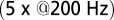 of the same cells as in A, averages of five sweeps. (E) Amplitude vs. delay of the maximal slow EPSC from 15 UBCs.
In rat UBCs, the initial fast EPSC is often followed by a transient increase of inward current, which rises to peak in hundreds of milliseconds (8–10). We reproduced this finding in mouse UBCs by applying a burst stimulation protocol, as shown in Fig. 1D for the same cells as in Fig. 1B. In response to five pulses at 200 Hz, a slow EPSC was observed that rose to a maximal amplitude of  in
in  in these two cells. Bath coapplication of NMDAR antagonist d-APV and AMPAR antagonist CNQX abolished the fast response and the subsequent slow wave, confirming their synaptic nature (gray traces). As exemplified by these recordings, the amplitude of the fast EPSC was generally unrelated to the amplitude of the slow EPSC. Fig. 1E plots the amplitude (base amp.) vs. the delay of the slow current maximum for 15 UBCs. The plotted values represent the maximal delays we were able to evoke for a given cell.
EPSCs Are Generated from a Steady State.
According to the glutamate-entrapment hypothesis, the origin of the slow EPSC tail current lies in the (quasi) steady-state activation of postsynaptic receptors, due to prolonged presence of glutamate in the synaptic cleft. To test this hypothesis, we designed a stimulation protocol to expose the UBC synapse to stepwise increasing glutamate concentrations in a reproducible way. We applied regular stimulus trains at stepwise increasing stimulation frequencies in the range of 0–20 Hz. Each stimulation frequency was maintained for at least 5 s, ensuring that peak and baseline amplitudes settled to their final stationary values. EPSCs during the last 4 s of a train were averaged, and corresponding values of EPSC peak amplitude, baseline amplitude, and baseline slope were determined. We refer to these values as steady-state values from here on.
Examples of steady-state EPSCs are displayed in Fig. 2A for five frequencies. Steady-state EPSC peaks declined monotonically with stimulation frequency. However, it is apparent from these examples that the baseline amplitude and slope of the steady-state EPSC depended in a nonintuitive way on the stimulation frequency. The steady-state baseline amplitude first increased with increasing stimulation frequency until a maximum was reached at 10 Hz. The baseline amplitude then decreased for higher frequencies, and the baseline slope correspondingly reversed sign. The three parameters (peak, base and slope) are plotted as a function of stimulation frequency in Fig. 2 B–D for eight UBCs, recapitulating the described steady-state behavior. By stepping the stimulation frequency in this way, we could effectively sample the biphasic EPSC waveform, progressively stepping the baseline current through different phases of the slow tail. This behavior is inconsistent with expectations from ordinary (leaky) integration of slow synaptic currents, strikingly demonstrating the special mode of excitatory transmission at the UBC synapse.
Fig. 2.

Steady-state EPSCs. (A) Examples of steady-state EPSCs, derived from regular stimulation protocols at increasing frequencies. The transparent red lines indicate the baseline slope, which is the slope of the EPSC just before stimulation. (B–D) Summary of steady-state EPSC peaks, baseline amplitudes, and baseline slopes, respectively, as a function of stimulation frequency for eight UBCs. As sample frequencies varied between cells, averages and SEM (red) were obtained by interpolation.
Graded Delays of Slow EPSCs.
Vestibular mossy fibers in vivo typically display background discharge rates of 5–10 Hz in anesthetized mice in the flocculus (15) or as averaged during a vestibular tilt stimulus in the uvula-nodulus (16). We therefore investigated the development of EPSC amplitudes during trains of presynaptic stimulation. Fig. 3A shows an example recording of the response to a regular train of 15 stimuli at 20 Hz. Three things are immediately apparent from the trace. First, the EPSC peaks displayed strong adaptation during the initial stage of the train. Second, the slow EPSC tails fused, forming a persistent baseline current. Finally, after the last stimulus in the train, the baseline current transiently resurged, in a manner that was reminiscent of the slow responses to burst stimulation in Fig. 1D. Examples of such tail currents for different stimulation frequencies are shown in the Inset. The latency of the maximal slow current was graded; it increased when the frequency of the preceding stimulus train was increased.
Fig. 3.

Delayed EPSC generation. (A) UBC response to a regular 20-Hz stimulus train. (Inset) Example traces of slow waves following regular stimulation at different frequencies. The 200-Hz curve was redrawn in gray beneath each trace for comparison. The vertical dotted line was drawn 20 ms after the final stimulus in the train. (B) Adaptation of EPSC peaks during 20-Hz stimulus trains  ; average and SEM are shown in red. (Inset) EPSC peak ratio (relative to the first EPSC) of the second and fifth peaks in a train, as a function of train stimulus frequency. (C) Example traces of responses to irregular stimulation (single sweep, 90 s) at average frequencies 5 (Upper Left, blue) and 10 Hz (Upper Right, red). Stimulation times, peaks of the fast EPSCs, and baseline currents before stimulations are indicated by markers. In the lower panels, EPSC peaks are plotted vs. the corresponding baseline currents for 5 (Lower Left, blue dots) and 10 Hz (Lower Right, red dots). Steady-state values derived from Fig. 2 are replotted here for this particular cell (black curve). (D) Heatmap of stacked traces of slow synaptic current during irregular stimulation of the cell in A. Traces with ISIs ≥ 350 ms were selected and sorted according to the value of baseline current at time 350 ms. (E) Latency of the maximal slow EPSC following regular stimulation, as a function of frequency for 11 UBCs. Individual curves resulted from at least five repetitions, and error bars indicate SD. The average curve is plotted in red, with error bars indicating SEM.
Fig. 3B shows the development of EPSC peaks during regular 20-Hz stimulation for 11 UBCs. Peaks depressed in all cells tested, on average by  after the first five stimuli. Depression then continued at a much slower pace, reaching on average
  after 10 stimuli. The Inset shows EPSC peak ratio (relative to the first EPSC) of the second and fifth peak in a train, as a function of stimulation frequency. The former thus corresponds to a classical paired-pulse experiment. Notably, significant depression of the EPSC peak already occurred at stimulation frequencies as low as 2 Hz.
Under natural conditions, mossy fiber activity is irregular due to the occurrence of bursts and pauses resulting from modulation by sensory inputs, for example. To investigate EPSC integration under such conditions in the in vitro preparation, we stimulated mossy fibers with trains of stimuli at irregular interstimulus intervals (ISIs). Fig. 3C shows example traces recorded during irregular stimulation at average frequencies of 5 (Left, blue) and 10 Hz (Right, red). Note that for these experiments, we used single (long lasting) trials, so the traces are not averages of multiple sweeps. As before, the EPSC peaks were detected, as well as the baseline amplitudes just before stimulation. These quantities are plotted against each other below the example traces, for instantaneous frequencies up to 20 Hz. The black overlayed curve was derived from the stimulation protocol described in Fig. 2 for this particular cell and thus represents steady-state amplitudes of the baseline and corresponding fast EPSC. The overlap of the black curve with the data points derived from the irregular stimulation protocol indicates that EPSCs were generated from a steady state, even during irregular stimulation patterns.
As was shown in Fig. 3A, regular stimulation trains were followed by slow resurgent EPSCs with controllable delays. Such slow EPSCs were also generated during irregular stimulation, as shown in the example of Fig. 3D. Here, periods with ISI ≥ 350 ms were selected from the stimulation trials and sorted according to the current amplitude at time 350 ms. These current traces were then stacked and displayed as a heatplot. It is apparent from the plot that slow EPSCs were activated with a wide range of delays, providing further illustration of their graded timing. Fig. S1 provides further examples and simulations of irregular stimulation protocols.
The properties of slow EPSC timing in response to regular stimulation trains are summarized in Fig. 3E, which plots the delay of the maximal slow EPSC as a function of the stimulation frequency for 11 UBCs. Delay was positively related to the stimulation frequency and typically extended up to 200 ms. The average SD of delays from trial to trial was  , corresponding to a trial-to-trial variability of 0.13 (coefficient of variation) for a 200-ms delay. Graded persistent activation thus allowed UBCs to controllably extend transmission delays in relation to the frequency of presynaptic activity, with low variability on a single-trial basis.
Slow EPSC Delays Result from Steady-State AMPAR Activation.
To elucidate the mechanism underlying slow EPSC generation, we simulated EPSCs using a kinetic AMPAR model from Raman and Trussell (2), which has been used previously to simulate EPSCs at a calyceal somatic synapse in cochlear nucleus (17) and at the mossy fiber to granule cell synapse (5). Fig. 4A shows the open probability Po (sum of three open states) of the model in response to a brief pulse of glutamate (4 mM, decay time  ), for increasing levels of the background glutamate concentration G. When G was stepwise increased from 0 to
  , the distribution of occupied model states increasingly shifted toward desensitized states, resulting in a decreasing Po amplitude
  . The relation between
  and G is plotted in Fig. 4B, showing that
  was a monotonically decreasing function of G. The dose–response curve, which is the steady-state open probability as a function of background glutamate concentration G, was bell-shaped (
 , red curve); it first rose to a maximum at around
  and then fell in response to increasing steady-state glutamate exposure. Thus, under steady-state conditions, both EPSC peak and base currents were instantaneously related to G.
Fig. 4.

AMPAR model simulations. (A) Schematic representation of the AMPAR model from Raman and Trussell (2). Traces are simulation results of total (summed) receptor open probability Po in response to a 4-mM pulse of glutamate for five values of the ambient glutamate concentration G. (B) Peak Po
 in response to a brief 4-mM glutamate pulse (black trace) as a function of G. The steady-state Po
 as a function of G is plotted in red. (C) Glutamate release and decay model. The background glutamate concentration G was modeled as an instantaneously released quantity, which decayed biexponentially to zero (black). The gray curves represent the fast glutamate peak (truncated) underlying the fast EPSC. Further details are described in the main text. (D)
  as a function of
  (black curve). The steady-state AMPAR model was fitted to experimental steady-state data (gray) with fit parameter α. (E) Results of fitting the biexponential glutamate decay model to EPSC base amplitudes obtained from regular stimulation experiments (Upper). Each fit was characterized by a pair of release amplitudes
  and decay time constants
  ; results are shown in the bottom panel for 11 UBCs. (F) Model fit to steady-state data of Fig. 2. Fit results are shown in red in E. (G) (Upper)
  as a function of time following 10 regular stimuli at varying stimulation frequency. The black curve denotes the time of maximal
  . (Lower) Delay of the maximal
  as a function of stimulation frequency for 10 stimuli.
The glutamate concentration underlying the steady-state AMPAR response was termed  and was described by the sum of two exponentially decaying components G1 and G2 with instantaneous release quantities Q1 and Q2 and decay time constants
  and
and  (Fig. 4C, Left). This part of the model corresponded to areas of the synapse that might contain AMPARs that are not directly opposed to release sites (Center) (9). The fast AMPAR peak response was generated from a background glutamate concentration
  that was a fraction α of
  . This part of the model corresponded to areas of the synapse with AMPARs directly opposing release sites (Right). An estimate of α could be obtained without using explicit assumptions on the time course of G, by directly associating
  with
with  , as shown in Fig. 4D. By circumventing G in this way, the resulting curve (black) could be directly compared with the steady-state data from Fig. 2. A least squares fit to the steady-state baseline values resulted in
  .
.
The glutamate model thus had four parameters: two release quantities  and two decay time constants
  . To translate glutamate concentrations into channel open probability during stimulus trains, we implemented a steady-state approximation by using the curves in Fig. 4B as a lookup table. In this way, the peak and baseline amplitudes were instantaneously related to the underlying glutamate concentration. This procedure allowed for estimating the effective background glutamate concentration in the synaptic cleft, by fitting simulated baseline
  to experimental EPSC baseline amplitudes. One additional parameter
  was introduced to translate open probability into current (pA). An example fit result is shown in the upper panel of Fig. 4E, for stimulus trains at three frequencies. Note that the black curves all resulted from the same model parameters and thus do not represent individual fits; the model was fitted simultaneously to base amplitude data at different frequencies, which were treated as a single dataset. An upper limit of
  was imposed on the fit procedure to prevent runaway parameter values in four cases. Fit results from 11 UBCs are summarized in the lower panel of Fig. 4E, where
  and
and  corresponding to each cell are represented as a set of connected coordinates. One cell was better described by a single-exponential decay (single black dot). The average values obtained from this procedure for glutamate decay time constants were
  and
and  (single-exponential value excluded). The slow time constant matched well with the (independently determined) slow time constant from the EPSC tail current in Fig. 1C. In Fig. 4F, these time constants were used to obtain an estimate of the glutamate release quantities by fitting to steady-state data from Fig. 2. The procedure resulted in an excellent fit to the steady-state baseline data. The fit parameters are shown in red in Fig. 4E and matched well with the fit results from the transient baseline adaptation experiments.
The model also naturally reproduced the variable slow EPSC delays. The upper panel of Fig. 4G shows the results from a simulation in which the model was first stimulated by 10 glutamate pulses and subsequently left to decay (from time  in the plot) according to the steady-state fit parameters. Due to increasing accumulation of glutamate, a delayed AMPAR activation gradually developed with increasing stimulation frequency. The black overlayed curve represents the maximal
  and corresponds to the curve in the lower panel. Delay was a monotonic function of the stimulation frequency, providing a direct mechanistic interpretation of the data in Fig. 3E. An additional result from the model was that delay also positively depended on the number of presynaptic stimuli, but this was not systematically investigated here.
Input-Output Transformations.
To communicate timed signals to the downstream cerebellar network, synaptic input currents need to be reliably translated into neuronal output by UBCs. In a separate set of experiments, we investigated how slow currents were able to shape neuronal output in UBCs, by recording action potentials during direct somatic injection of time-varying currents in the current-clamp configuration (Fig. 5). UBCs are capable of generating action potentials at a regular pace in vitro (18) and in vivo (16, 19). We therefore set UBCs to fire action potentials at a regular pace of 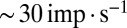 by constant current injection, and subsequently, modulated firing rates using sinusoidal waveforms with a range of frequencies. UBCs linearly encoded input waveforms with 5- to 10-pA amplitudes, with virtually flat gain
  and phase
  over the full range of input frequencies (Fig. 5B). A slow signal with 10-pA amplitude, for example, would result in a maximal increase of
  in UBC firing rate. On a trial-to-trial basis, the peak of such a signal would then be represented by UBCs with
  resolution or better. These results indicated that UBCs could accurately and reliably transform timing of slow current input into action potential output.
Fig. 5.

Modulation of action potential generation. (A) Examples of modulation of action potential firing in response to direct somatic injection of sinusoidal currents at 1 and 2 Hz. (Top) Injected current. (Middle) Recorded voltage. (Bottom) Average instantaneous firing rate from 20 (1 Hz) and 40 (2 Hz) sweeps. (B) Gain and phase of the input-output transformation as a function of sinusoidal frequency for a total of 21 UBCs. The trace corresponding to the example cell in A is shown in black; average and SEM are shown in red.
Discussion
The role of spatial transformations in the input layer of the cerebellum is a topic of debate, inspired by the anatomy of divergent mossy fiber-granule cell projections. In contrast, less attention has been paid to the origin of temporal transformations in the granular layer, and mechanisms have been mostly restricted to the millisecond time scale (20). Here we show that UBCs in the granular layer of the mouse produced slow resurgent EPSCs that could be activated with variable delays up to hundreds of milliseconds, in direct relation to the frequency of presynaptic stimuli. Furthermore, we provide a mechanistic interpretation of EPSC integration, by combining customized stimulation patterns with a kinetic model of AMPAR activation. These results show that UBCs can provide a basis for temporal coding in the cerebellar cortex.
EPSC Integration.
Considering the large number of glutamate release sites and the extensive area of the postsynaptic density, the UBC EPSC peak is surprisingly small, comparable in amplitude to granule cell EPSCs (21). Moreover, during regular trains of presynaptic stimulation, EPSC peaks displayed significant depression within the first five stimuli that already became almost complete at a stimulation frequency of 20 Hz. This result stands in stark contrast to mossy fiber-granule cell EPSCs, for which short-term depression is virtually absent at comparable rates (15, 21). Furthermore, the relatively large capacitance of the UBC membrane reduces the capacity for fast EPSC components to depolarize UBCs, as currents are effectively low-pass filtered while charging the cell. UBC synaptic physiology thus appears particularly suited to slow signal transmission.
Due to relatively high background activity, combined with slow glutamate removal from the cleft, the physiological state of the UBC synapse in vivo is likely characterized by long periods of continuous exposure to glutamate. During long-lasting stimulation patterns in our in vitro preparation, UBCs generated slow resurgent EPSCs with variable delays that were well described as resulting from steady-state AMPAR activation. Comparing different UBCs, the extent of the delay varied widely between cells, which by itself could have important functional implications (14). For individual UBCs, modulation of the slow EPSC delay took place with little variation in EPSC amplitude, allowing for a fully independent representation of temporal intervals. Slow EPSCs were generated reliably on a trial-to-trial basis, and UBCs could accurately represent timing of slow signals in their action potential output. UBC signal transmission will be further shaped by coupling of (extra)synaptic inputs to intrinsic cellular mechanisms underlying action potential generation.
Slow depolarizations with graded delays were also recently observed in UBCs in response to mossy fiber bundle stimulation, due to a nonsynaptic activation (11). Such a mechanism could diffusively activate the granular layer with delays up to seconds. This type of UBC activation is distinctly different from the type described in our current work in three ways: First, it required electrical stimulation of the entire mossy fiber bundle at high intensity (typically 10–20 pulses at 100 Hz). Second, UBC depolarization was mediated through a diffusive nonsynaptic mechanism and was therefore most likely not cell specific. Third, the extent of the delay decreased when the frequency and number or intensity of stimuli were increased. These findings stand in contrast to our results on all accounts and therefore represent a fundamentally different physiological mechanism in the cerebellar circuit.
Model and Simulations.
Despite the morphological complexity of the UBC synapse, we were able to capture both transient and steady-state behavior of the slow EPSC baseline using a scalar model for glutamate release and decay. An explanation is that rapid equilibration of glutamate across the synaptic cleft results in a spatially homogeneous glutamate concentration profile, which supports an equilibrium distribution of open channels in a large ensemble of AMPARs. Slow baseline currents can then be simulated as (quasi) steady-state activation of a kinetic AMPAR model, driven by a single effective glutamate concentration.
Several features of fast EPSC peak adaptation were also described by the model, such as significant depression at stimulation frequencies as low as 2 Hz and rapid adaptation to nearly full depression at 20 Hz. These observations point to a common underlying mechanism driving EPSC baseline and peak adaptation, as the two parameters covaried during transient stimulation (Fig. S2). Nonetheless, the rate of peak adaptation was not in full accordance with steady-state behavior, as would have been expected from the model (Fig. S3). Furthermore, an additional very slow peak adaptation component was apparent during long stimulus trains, which was not described by the model (Figs. S4 and S5). These discrepancies could, for example, be explained by presynaptic adaptation processes, which were not simulated here.
Role in Cerebellar Learning and Timing.
The cerebellar cortex is crucial for the timed execution of movements (22). At the cellular level, this task requires accurate neural activity on multiple time scales, to facilitate adaptive output for motor control (14). The mechanism described in this work allows individual UBCs to tailor transmission delays to match varying degrees of synaptic input. Considering the abundance of UBCs in the vestibulo-cerebellum, this functionality could be especially relevant to relatively slow compensatory movements of the eyes and head. For example, activation of vestibular mossy fibers (known to signal head velocity) (15) by a strong head movement could result in a broadening of available delays in the UBC population, as different UBCs are differently attuned to the input. The sensitivity of this mechanism might be tuned by presynaptic plasticity, for example, by modulating glutamate release probability.
Transmission delays beyond the typical neuronal membrane time constants are of central importance to many models of cerebellum-dependent behavior. Nonetheless, it remains unclear in most cases how such delays could come about. For example, transmission delays are crucial to the process of signal integration in feedback circuits, which might underlie vestibular oculo-motor integration (23). In models of eyeblink conditioning and vestibulo-ocular reflex (VOR) adaptation, the cerebellar granular layer is often specifically postulated as the source of neural transmission delays and tonic signals (24, 25), and an eligibility trace with a peak at 200–250 ms has been postulated as a general feature of cerebellum-dependent forms of learning (26). UBCs are thus well positioned to provide a robust cellular substrate for representing time intervals in the cerebellar cortex.
Materials and Methods
Parasagittal sections (250 μm) were cut from the cerebellar vermis of C57BL/6 mice (5–7 wk old) in ice-cold bicarbonate-buffered solution containing the following (in mM): 90 NaCl, 2.5 KCl, 1.25 NaH2PO4, 26 NaHCO3, 0.5 CaCl2, 4 MgCl2, 25 d-glucose, 75 sucrose, and 1 kynurenic acid [bubbled with 95% (vol/vol) O2, 5% (vol/vol) CO2]. After cutting, slices were allowed to recover for 1 h in artificial cerebrospinal fluid (ACSF) at 34 °C containing: 127 NaCl, 2.5 KCl, 1.25 NaH2PO4, 26 NaHCO3, 1.5 CaCl2, 1 MgSO4, and 20 d-glucose [bubbled with 95% (vol/vol) O2, 5% (vol/vol) CO2]. For electrophysiology, slices were continuously perfused with bubbled ACSF (2 mL/min) at room temperature  . ACSF was supplemented with
  picrotoxin and
  strychnine to block inhibitory synaptic transmission. Current-clamp recordings were performed in the presence of 1 mM kynurenic acid or a mixture of
  d-APV and
  CNQX to block excitatory synaptic transmission. For current-clamp recordings (21 cells) and a subset of the voltage-clamp recordings (15 cells), filamented borosilicate pipettes were filled with an intracellular solution containing the following (in mM): 140 K-gluconate, 0.2 EGTA, 10 Hepes, 4 Na2ATP, 0.4 Na3GTP, and 2 MgCl2 (290 mOsm, pH 7.3 set with KOH). For other voltage-clamp recordings (seven cells), the intracellular solution was as follows (in mM): 140 CsMeSO3, 1 EGTA, 10 Hepes, 4 Na2ATP, 0.4 Na3GTP, 2 MgCl2, 0.2 CaCl2, 1 QX-314, and 1 TEA-Cl (290 mOsm, pH 7.3 set with CsOH). As a reference electrode, an Ag/AgCl wire was connected to the bath through an agarose salt bridge. The identity of UBCs could be confirmed by their whole-cell capacitance
 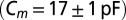 and passive membrane resistance
 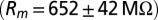 . Access resistance
  was compensated
  . For stimulation experiments, double- or single-barrel borosilicate glass pipettes were filled with Hepes-buffered ACSF and placed to evoke a reliable synaptic response from the white matter or granular layer. Data analysis was performed with MATLAB (Mathworks), and model simulations were performed using NEURON and Python.
A detailed description of the materials and methods is provided in SI Materials and Methods.
Supplementary Material
Acknowledgments
We thank Boeke van Beugen, Elisa Galliano, Zhenyu Gao, and Freek Hoebeek for valuable discussions and help with slice preparations in the initial stage of the work. C.I.D.Z. is supported by the Dutch Organization for Life Sciences (ZonMw), an advanced grant of the European Research Counsel, and the CEREBNET and C7 programs of the European Union.
Footnotes
The authors declare no conflict of interest.
This article is a PNAS Direct Submission.
This article contains supporting information online at www.pnas.org/lookup/suppl/doi:10.1073/pnas.1314219111/-/DCSupplemental.
References
- 1.Zucker RS, Regehr WG. Short-term synaptic plasticity. Annu Rev Physiol. 2002;64:355–405. doi: 10.1146/annurev.physiol.64.092501.114547. [DOI] [PubMed] [Google Scholar]
- 2.Raman IM, Trussell LO. The mechanism of alpha-amino-3-hydroxy-5-methyl-4-isoxazolepropionate receptor desensitization after removal of glutamate. Biophys J. 1995;68(1):137–146. doi: 10.1016/S0006-3495(95)80168-2. [DOI] [PMC free article] [PubMed] [Google Scholar]
- 3.DiGregorio DA, Rothman JS, Nielsen TA, Silver RA. Desensitization properties of AMPA receptors at the cerebellar mossy fiber granule cell synapse. J Neurosci. 2007;27(31):8344–8357. doi: 10.1523/JNEUROSCI.2399-07.2007. [DOI] [PMC free article] [PubMed] [Google Scholar]
- 4.Otis T, Zhang S, Trussell LO. Direct measurement of AMPA receptor desensitization induced by glutamatergic synaptic transmission. J Neurosci. 1996;16(23):7496–7504. doi: 10.1523/JNEUROSCI.16-23-07496.1996. [DOI] [PMC free article] [PubMed] [Google Scholar]
- 5.Xu-Friedman MA, Regehr WG. Ultrastructural contributions to desensitization at cerebellar mossy fiber to granule cell synapses. J Neurosci. 2003;23(6):2182–2192. doi: 10.1523/JNEUROSCI.23-06-02182.2003. [DOI] [PMC free article] [PubMed] [Google Scholar]
- 6.Mugnaini E, Floris A, Wright-Goss M. Extraordinary synapses of the unipolar brush cell: An electron microscopic study in the rat cerebellum. Synapse. 1994;16(4):284–311. doi: 10.1002/syn.890160406. [DOI] [PubMed] [Google Scholar]
- 7.Eccles JC, Jaeger JC. The relationship between the mode of operation and the dimensions of the junctional regions at synapses and motor end-organs. Proc R Soc Lond B Biol Sci. 1958;148(930):38–56. doi: 10.1098/rspb.1958.0003. [DOI] [PubMed] [Google Scholar]
- 8.Rossi DJ, Alford S, Mugnaini E, Slater NT. Properties of transmission at a giant glutamatergic synapse in cerebellum: The mossy fiber-unipolar brush cell synapse. J Neurophysiol. 1995;74(1):24–42. doi: 10.1152/jn.1995.74.1.24. [DOI] [PubMed] [Google Scholar]
- 9.Kinney GA, Overstreet LS, Slater NT. Prolonged physiological entrapment of glutamate in the synaptic cleft of cerebellar unipolar brush cells. J Neurophysiol. 1997;78(3):1320–1333. doi: 10.1152/jn.1997.78.3.1320. [DOI] [PubMed] [Google Scholar]
- 10.Diana MA, et al. T-type and L-type Ca2+ conductances define and encode the bimodal firing pattern of vestibulocerebellar unipolar brush cells. J Neurosci. 2007;27(14):3823–3838. doi: 10.1523/JNEUROSCI.4719-06.2007. [DOI] [PMC free article] [PubMed] [Google Scholar]
- 11.Locatelli F, Bottà L, Prestori F, Masetto S, d’Angelo E. Late-onset bursts evoked by mossy fibre bundle stimulation in unipolar brush cells: Evidence for the involvement of H- and TRP-currents. J Physiol. 2013;591(Pt 4):899–918. doi: 10.1113/jphysiol.2012.242180. [DOI] [PMC free article] [PubMed] [Google Scholar]
- 12.Nunzi MG, Mugnaini E. Unipolar brush cell axons form a large system of intrinsic mossy fibers in the postnatal vestibulocerebellum. J Comp Neurol. 2000;422(1):55–65. doi: 10.1002/(sici)1096-9861(20000619)422:1<55::aid-cne4>3.0.co;2-9. [DOI] [PubMed] [Google Scholar]
- 13.Mugnaini E, Sekerková G, Martina M. The unipolar brush cell: A remarkable neuron finally receiving deserved attention. Brain Res Brain Res Rev. 2011;66(1-2):220–245. doi: 10.1016/j.brainresrev.2010.10.001. [DOI] [PMC free article] [PubMed] [Google Scholar]
- 14.Gao Z, van Beugen BJ, De Zeeuw CI. Distributed synergistic plasticity and cerebellar learning. Nat Rev Neurosci. 2012;13(9):619–635. doi: 10.1038/nrn3312. [DOI] [PubMed] [Google Scholar]
- 15.Arenz A, Silver RA, Schaefer AT, Margrie TW. The contribution of single synapses to sensory representation in vivo. Science. 2008;321(5891):977–980. doi: 10.1126/science.1158391. [DOI] [PMC free article] [PubMed] [Google Scholar]
- 16.Barmack NH, Yakhnitsa V. Functions of interneurons in mouse cerebellum. J Neurosci. 2008;28(5):1140–1152. doi: 10.1523/JNEUROSCI.3942-07.2008. [DOI] [PMC free article] [PubMed] [Google Scholar]
- 17.Otis TS, Wu Y-C, Trussell LO. Delayed clearance of transmitter and the role of glutamate transporters at synapses with multiple release sites. J Neurosci. 1996;16(5):1634–1644. doi: 10.1523/JNEUROSCI.16-05-01634.1996. [DOI] [PMC free article] [PubMed] [Google Scholar]
- 18.Russo MJ, Mugnaini E, Martina M. Intrinsic properties and mechanisms of spontaneous firing in mouse cerebellar unipolar brush cells. J Physiol. 2007;581(Pt 2):709–724. doi: 10.1113/jphysiol.2007.129106. [DOI] [PMC free article] [PubMed] [Google Scholar]
- 19.Ruigrok TJ, Hensbroek RA, Simpson JI. Spontaneous activity signatures of morphologically identified interneurons in the vestibulocerebellum. J Neurosci. 2011;31(2):712–724. doi: 10.1523/JNEUROSCI.1959-10.2011. [DOI] [PMC free article] [PubMed] [Google Scholar]
- 20.D’Angelo E, De Zeeuw CI. Timing and plasticity in the cerebellum: Focus on the granular layer. Trends Neurosci. 2009;32(1):30–40. doi: 10.1016/j.tins.2008.09.007. [DOI] [PubMed] [Google Scholar]
- 21.Saviane C, Silver RA. Fast vesicle reloading and a large pool sustain high bandwidth transmission at a central synapse. Nature. 2006;439(7079):983–987. doi: 10.1038/nature04509. [DOI] [PubMed] [Google Scholar]
- 22.De Zeeuw CI, Yeo CH. Time and tide in cerebellar memory formation. Curr Opin Neurobiol. 2005;15(6):667–674. doi: 10.1016/j.conb.2005.10.008. [DOI] [PubMed] [Google Scholar]
- 23.Arnold DB, Robinson DA. The oculomotor integrator: Testing of a neural network model. Exp Brain Res. 1997;113(1):57–74. doi: 10.1007/BF02454142. [DOI] [PubMed] [Google Scholar]
- 24.Raymond JL, Lisberger SG. Neural learning rules for the vestibulo-ocular reflex. J Neurosci. 1998;18(21):9112–9129. doi: 10.1523/JNEUROSCI.18-21-09112.1998. [DOI] [PMC free article] [PubMed] [Google Scholar]
- 25.Dean P, Porrill J, Stone JV. Decorrelation control by the cerebellum achieves oculomotor plant compensation in simulated vestibulo-ocular reflex. Proc Biol Sci. 2002;269(1503):1895–1904. doi: 10.1098/rspb.2002.2103. [DOI] [PMC free article] [PubMed] [Google Scholar]
- 26.Medina JF, Carey MR, Lisberger SG. The representation of time for motor learning. Neuron. 2005;45(1):157–167. doi: 10.1016/j.neuron.2004.12.017. [DOI] [PubMed] [Google Scholar]
Associated Data
This section collects any data citations, data availability statements, or supplementary materials included in this article.