Abstract
Low-work-function active metals are commonly used as cathode in polymer solar cells (PSCs), but sensitivity of the active metals towards moisture and oxygen results in poor stability of the devices. Therefore, solution-proceessable and stable cathode buffer layer is of great importance for the application of PSCs. Here we demonstrate high performance PSCs by employing as-prepared zirconium acetylacetonate (a-ZrAcac) film spin-cast from its ethanol solution as cathode buffer layer. The PSCs based on a low bandgap polymer PBDTBDD as donor and PC60BM as acceptor with a-ZrAcac/Al cathode demonstrated an average power conversion efficiency (PCE) of 8.75% which is significantly improved than that of the devices with traditional Ca/Al cathode. The improved photovoltaic performance is benefitted from the decreased series resistance and enhanced light harvest of the PSCs with the a-ZrAcac/Al cathode. The results indicate that a-ZrAcac is a promising high performance cathode buffer layer for fabricating large area flexible PSCs.
Since the first reports of photo-induced electron transfer from a conjugated polymer to fullerene1, polymer solar cells (PSCs) have attracted exclusive attention due to low-cost, light-weight, and mechanical flexibility with compatibility to future large-area roll-to-roll printing production. The performance of PSCs depends not only on the electronic energy levels, absorption and carrier mobility of the conjugated polymer donor and fullerene derivative acceptor photovoltaic materials2,3,4,5, but also on the effective charge extraction of both holes and electrons from the photoactive layer and then collection to the respective anode and cathode6,7,8,9. Therefore, the electrode materials or the electrode buffer layers play a key role in improving photovoltaic performance of the PSCs7,8. High workfunction anode buffer layers and low workfunction cathode buffer layers are pursued in selecting the electrode buffer layers.
Low-work-function active metals, such as Ca, Ba and Mg, are commonly used as cathode for efficient electron extraction in PSCs, but the active metals are very sensitive to environmental moisture and oxygen, resulting in poor stability of the devices10,11,12,13,14. Therefore, solution-proceessable and stable cathode buffer layer (CBL) is of great importance for promoting the application of PSCs15,16,17. Recently, solution processable transition metal oxides (ZnO18,19,20,21 and TiOx22,23,24,25), transition metal chelates26,27,28,29,30, and conjugated polyelectrolytes31,32,33, have been successfully used as the CBLs. Nevertheless, compared with anode buffer layer, the CBL is still very limited, and air-stable, facile-processed, easily obtained CBLs are in great request. Recently, a wide bandgap oxide, zirconium oxide (ZrO2), deposited by spray pyrolysis34, electron beam evaporation35 or atomic layer deposition36, was successfully utilized as electron injection layer in inverse and conventional polymer light-emitting diodes. The greatly enhancement in device performance was attributed to the suitable energy levels of ZrO2 which have hole-blocking and electron injection ability34,35,36. However, there is no report about using zirconium based materials as CBLs in PSCs.
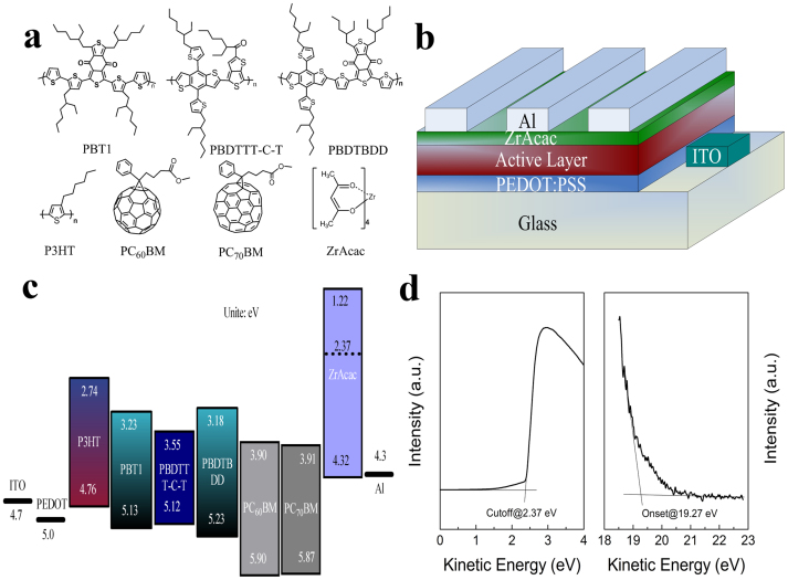
In this work, we demonstrate high performance PSCs by employing as-prepared zirconium acetylacetonate film (a-ZrAcac) as CBL. The a-ZrAcac CBL was simply prepared by spin-coating its ethanol solution on photoactive layer at room temperature, no thermal annealing or any other post-treatment was performed. To investigate the photovoltaic performance of the a-ZrAcac CBL, bulk-heterojunction PSCs based on P3HT (poly(3-hexylthiophene)) or low bandgap D-A copolymer PBT1 (poly(1,3-bis(2-ethylhexyl)-5,7-bis(4-(2-ethylhexyl)thiophen-2-yl)benzo[1,2-c:4,5-c′]dithiophene-4,8-dione)-co-(2,2′-bithiophene)), PBDTTT-C-T (poly(4,8-bis(5-(2-ethylhexyl)-thiophene-2-yl)-benzo[1,2-b:4,5-b′]dithiophene-alt -alkylcarbonyl-thieno[3,4-b]thiophene)), and PBDTBDD (poly(((4,8-Bis(5-(2-ethylhexyl)thiophen-2-yl)benzo[1,2-b:4,5-b′]dithiophene-2,6-diyl) bis(trimethyl))-co-(5,7-bis(2-ethylhexyl)benzo[1,2-c:4,5-c′]dithiophene-4,8-dione))) as electron donor and PC60BM or PC70BM as electron acceptor were fabricated with a-ZrAcac/Al as cathode. The molecular structures of donor, accepter and ZrAcac are shown in Figure 1(a). The power conversion efficiency (PCE) of the P3HT:PC60BM-based device with a-ZrAcac CBL reaches 4.23%, which is nearly 60% increased in comparison with the PSC without the buffer layer and ca. 12% increased than that of the PSC with traditional Ca/Al cathode. For the PSCs with low bandgap polymer PBDTBDD as electron donor, an average PCE of 8.75% with a maximum of 9.23% was achieved with a-ZrAcac CBL, greatly improved in comparison to the devices with Al (5.72%) or Ca/Al (7.34%) as cathode.
Figure 1.
(a) Molecular structures of P3HT, PBT1, PBDTBDD-C-T, PBDTBDD, PC60BM, PC70BM and ZrAcac; (b) Device structure of the polymer solar cells; (c) Schematic energy diagram of the materials involved in the PSCs; (d) UPS spectra of a-ZrAcac on ITO substrate.
Results
The a-ZrAcac layer is highly transparent in the visible wavelength range as shown in Figure S1 in Supporting Information (SI) and bearing an amorphous structure confirmed by XRD (Figure S2 in SI). The characteristic absorption peak of acetylacetonate located at 300 nm attributes to the n-π* and π-π* intra-ligand electronic transitions37,38. The transparence of the a-ZrAcac layer will benefit the transmission and reflection on the back Al electrode for the transmitted light through the active layer, which will potentially increase the light harvest of the photoactive layer and thus enhance the photocurrent of the PSCs. a-ZrAcac possesses a high stability constant39 and is thermally stable at lower than 150°C as shown in the thermogravimetric analysis (TGA) and differential thermal analysis (DTA) plots in Figure S3 in SI. Our result is in good agreement with previous study40.
The effects of a-ZrAcac CBL on the photovoltaic performance of PSCs were examined by constructing the traditional structured devices of ITO/PEDOT:PSS/Active layer/a-ZrAcac/Al, as shown in Figure 1(b). In the PSCs, the active layer is P3HT:PC60BM, P3HT:PC70BM, PBT1:PC70BM, PBDTTT-C-T:PC70BM or PBDTBDD:PC60BM blend film, PEDOT:PSS is poly(3,4-ethylenedioxythiophene):poly(styrenesulfonate). Figure 1(c) shows the highest occupied molecular orbital (HOMO) and the lowest unoccupied molecular orbital (LUMO) energy levels of P3HT41, PBDTBDD42, PBT143, PBDTTT-C-T44, PC60BM45, PC70BM46 and a-ZrAcac, where the energy levels of ZrAcac were measured by ultraviolet photoelectron spectroscopy (UPS). Figure 1(d) illustrates the UPS spectra taken from the ZrAcac coated on ITO substrate. The work function can be deduced from the energy of the secondary cutoff, which is 2.37 eV. The HOMO level can be calculated as 4.32 eV from the difference between the incident light energy (He I, 21.22 eV) and the energy of the onset (19.27 eV) as well as the work function. The LUMO level of 1.22 eV was obtained from the band gap of 3.1 eV (determined from onset of the absorption (400 nm) (see Figure S1 in SI)) and the HOMO level. The energy level alignment at the photoactive blend layer/a-ZrAcac interface is very important for high performance PSCs. The extremely low work function of ZrAcac (2.37 eV) lies above the LUMO energy levels of PC60BM (3.90 eV) and PC70BM (3.91 eV), inducing the interfacial dipole formation across this interface, which will facilitate “barrier-free” electron extraction from the LUMOs of PC60BM and PC70BM47. The good energy level matching of ZrAcac can expect excellent electron extraction from photoactive layer and enhanced performance of the PSCs.
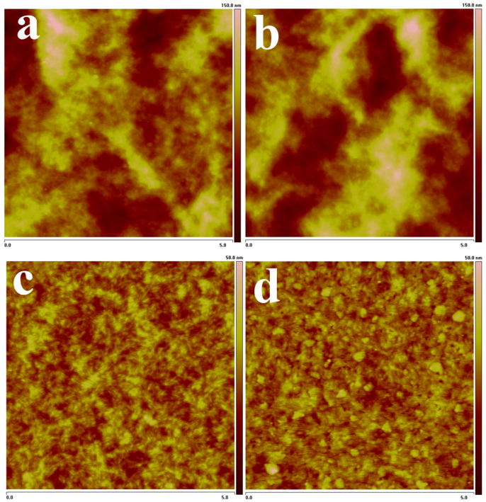
Surface morphology of a-ZrAcac layer spin-coated on clean ITO glass surface was investigated by tapping-mode atomic force microscopy (AFM), as shown in Figure S4 in SI. The AFM image shows a root-mean-square (rms) roughness of 3.4 nm, which is a little lower than that (4.6 nm) of bare ITO surface as shown in Figure S5. The surface morphologies of the photoactive layer with and without a-ZrAcac CBL were also investigated by AFM, as illustrated in Figure 2. The rms roughness of the blend layer of P3HT:PC60BM is 16.9 nm (Figure 2(a)), while the surface covered by the a-ZrAcac layer becomes more rough with a rms of 19.6 nm (Figure 2(b)). The same roughness changing trend but smaller roughness was observed for the blend layers of PBDTBDD:PC60BM. The rms roughness of the blend layers of PBDTBDD:PC60BM with and without a-ZrAcac CBL is 5.5 nm (Figure 2(d)) and 2.7 nm (Figure 2(c)), respectively. The increased roughness for the active layers with a-ZrAcac CBL could increase the contact area with the Al electrode deposited on it48.
Figure 2. AFM images of P3HT:PC60BM blend film on ITO/PEDOT:PSS substrate without (a) and with (b) a-ZrAcac layer, and AFM images of PBDTBDD:PC60BM blend film on ITO/PEDOT:PSS substrate without (c) and with (d) a-ZrAcac layer.
The scan size is 5 μm × 5 μm.
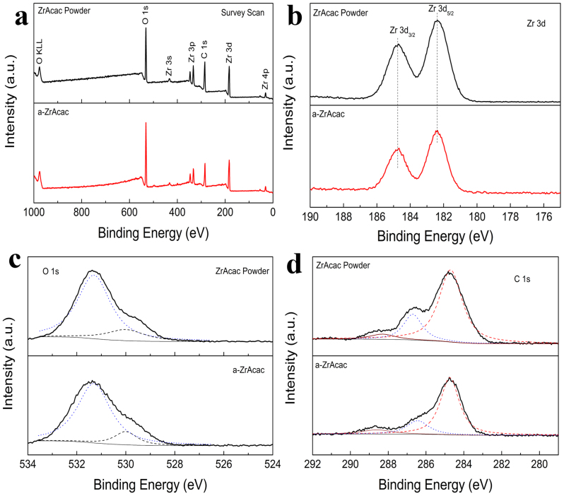
The chemical component of ZrAcac powder and as prepared Zracac layer (a-ZrAcac, 40 nm) on glass slide was analyzed by X-ray photoelectron spectroscopy (XPS) as shown in Figure 3. The binding energies (BE) obtained in the XPS analysis are corrected for specimen charge by referencing the C 1 s peak to 284.8 eV. As shown in Figure 3(a), the survey scan for both powder and thin film samples performed in the 0–1000 eV BE range show characteristic peaks of the elements Zr, O, and C. As shown in Figure 3(b), the XPS spectrum of the core level of Zr 3d for the powder sample has a strong spin–orbit doublet due to Zr 3d5/2 at 182.3 eV and Zr 3d3/2 at 184.7 eV49,50. The XPS spectrum is constrained by the Zr 3d5/2–Zr 3d3/2 spin–orbit separation being 2.4 eV, and the area ratio of the two peaks of each doublet being 3:2. These features are characteristic of Zr4+ ions in full oxidation states49,50. In the XPS spectrum of the a-ZrAcac thin film sample, the peaks corresponding to Zr 3d5/2 and Zr 3d3/2 are unchanged at 182.3 eV and 184.7 eV, respectively, with an Zr 3d5/2–Zr 3d3/2 spin–orbit separation of 2.4 eV and an intensity ratio of 3:2. The results indicate that the zirconium in the thin film sample is also in the Zr4+ oxidation state. The O 1 s XPS spectra for the powder and thin film samples are shown in Figure 3(c). It can be observed that the original powder sample presents nonsymmetric O 1 s peak centered at 531.3 eV with a shoulder around 530 eV. The peak at 531.3 eV corresponds to the oxygen in the acetylacetonic ligand cycle30, while the shoulder at 530 eV should attribute to the oxygen bonded with zirconium49,50, which means there is a small portion (17% from the peak fitting) of Zr4+ ions coordinate less than four acetylacetonic ligands in the original power sample and this is a common case in coordination complexes51. The thin film sample shows similar O 1 s peak, and the portion of non-four-coordination is 15%, which means there is no decomposition occurred. As shown in Figure 3(d), the C 1 s peaks of ZrAcac powder are located at 284.7 eV, which is assigned to the carbon in C-H/C-C group52, the peak at 286.7 eV corresponds to the carbon in delocalized C = O of ligand cycle52, and the weak shoulder at 288.3 eV attributes to the absorbed CO2 from ambient atmosphere52. The atomic ratio of C 1 s (286.7 eV) and C 1 s (284.7 eV) peaks is 1:3.50, which is very close to the ratio of 1:3.54 for thin film sample. The XPS results confirm that there is no structure change between the powder and the obtained thin film.
Figure 3. X-ray photoelectron spectroscopy (XPS) of ZrAcac powder and a-ZrAcac film (40 nm) on glass substrate.
(a) survey scan, (b) Zr 3d, (c) O 1s, and (d) C 1s core level spectra.
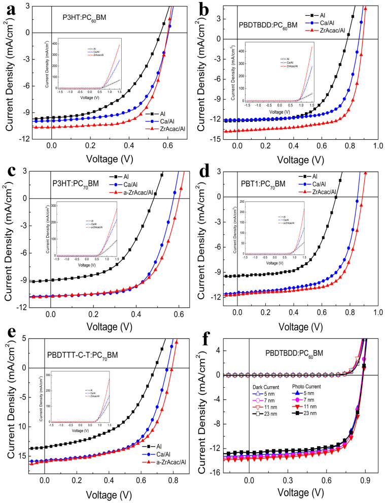
Figure 4 shows current density-voltage (J-V) curves of the PSCs based on P3HT:PC60BM, PBDTBDD:PC60BM, P3HT:PC70BM, PBT1:PC70BM and PBDTTT-C-T:PC70BM with different cathode in the dark and under the illumination of AM 1.5 G, 100 mW/cm2. The device performance parameters are given in Table 1, which are average values of 20 individual devices. For example, the Voc, Jsc, FF and PCE for PBDTBDD:PC60BM based on 20 devices are listed in Table S1 in SI. As shown in the inset of Figure 4(a), the J-V curves measured in the dark for the PSCs based on P3HT:PC60BM show quite different charge injection and rectification behavior for the devices with different cathode. At positive bias of 1.5 V, the injection current of the device with Al cathode is 72.3 mA/cm2, with a rectification ratio of 8.03 × 10³ at ±1.5 V. While that of the device with Ca/Al as cathode increased to 250.2 mA/cm2 with a rectification ratio of 1.39 × 10⁴. Interestingly, when utilizing a-ZrAcac/Al as cathode, the injection current is dramatically increased to 388.8 mA/cm2 with a rectification ratio of 3.09 × 10⁴, which is even much higher than that of the Ca/Al based device. The ZrAcac CBL works very well in PBDTBDD:PC60BM based devices, the injection current at 1.5 V and rectification ratio at ±1.5 V for device with ZrAcac buffer layer (Figure 4(b) inset) reach 436.0 mA/cm2 and 9.91 × 10³, respectively, much higher than that of the PSCs with Ca/Al (275.9 mA/cm2, 2.39 × 10³) or Al (59.7 mA/cm2, 1.90 × 10³) as cathode. The enhanced charge injection and improved rectification ratio also can be seen in PC70BM based P3HT (Figure 4(c)) and low bandgap PBT1 (Figure 4(d)) and PBDTTT-C-T (Figure 4(e)) devices with a-ZrAcac CBL.
Figure 4.
J−V curves under the illumination of AM 1.5 G, 100 mW/cm2 for the PSCs based on (a) P3HT:PC60BM, (b) PBDTBDD:PC60BM, (c) P3HT:PC70BM, (d) PBT1:PC70BM, and (e) PBDTTT-C-T:PC70BM with different cathode, insets are dark current at full bias scan from −1.5 V to 1.5 V; (f) J−V curves of the PSCs based on PBDTBDD:PC60BM with varied thickness of a-ZrAcac cathode buffer layer.
Table 1. Device parameters of the PSCs based on P3HT:PC60BM, PBDTBDD:PC60BM, P3HT:PC70BM, PBT1:PC70BM and PBDTTT-C-T:PC70BM with different cathode under the illumination of AM 1.5 G, 100 mW/cm2.
| Active Layer | Cathode | Voc (V) | Jsc (mA/cm2) | FF (%) | PCE (%) | Rs[a] (Ω cm2) |
|---|---|---|---|---|---|---|
| P3HT:PC60BM | Al | 0.56 | 9.55 | 49.6 | 2.65 | 13.0 |
| Ca/Al | 0.60 | 9.95 | 62.8 | 3.75 | 3.5 | |
| a-ZrAcac/Al | 0.60 | 10.66 | 66.1 | 4.23 | 2.3 | |
| PBDTBDD:PC60BM | Al | 0.78 | 12.10 | 60.6 | 5.72 | 11.5 |
| Ca/Al | 0.86 | 12.06 | 70.8 | 7.34 | 2.0 | |
| a-ZrAcac/Al | 0.88 | 14.28 | 69.6 | 8.75 | 1.2 | |
| P3HT:PC70BM | Al | 0.55 | 9.11 | 56.5 | 2.83 | 8.9 |
| Ca/Al | 0.58 | 10.71 | 62.5 | 3.88 | 3.8 | |
| a-ZrAcac/Al | 0.60 | 10.73 | 62.3 | 4.01 | 2.8 | |
| PBT1:PC70BM | Al | 0.70 | 9.50 | 58.9 | 3.92 | 12.4 |
| Ca/Al | 0.86 | 11.44 | 64.4 | 6.34 | 5.1 | |
| a-ZrAcac/Al | 0.88 | 11.68 | 68.7 | 7.06 | 3.2 | |
| PBDTTT-C-T:PC70BM | Al | 0.68 | 13.47 | 49.7 | 4.55 | 5.4 |
| Ca/Al | 0.76 | 15.76 | 60.3 | 7.22 | 4.0 | |
| a-ZrAcac/Al | 0.79 | 15.95 | 60.0 | 7.55 | 2.4 |
[a]Series resistance (Rs) of the PSCs in the dark are obtained at around 1.2 V.
The PSCs based on P3HT:PC60BM with only Al cathode gives a PCE of 2.65%, with an open-circuit voltage (Voc) of 0.56 V, a short-circuit current density (Jsc) of 9.55 mA/cm2, and a fill factor (FF) of 49.6%. In contrast, the four parameters of Voc, Jsc, FF, and PCE for the device with a-ZrAcac/Al cathode are all enhanced to 0.60 V, 10.66 mA/cm2, 66.1%, and 4.23%, respectively. The photovoltaic performance of the device with a-ZrAcac/Al cathode is also significantly improved than that of the device with traditional Ca/Al cathode with PCE increased by 12.8%. Furthermore, the a-ZrAcac CBL shows excellent performance in the PSCs based on low bandgap D-A copolymer PBDTBDD:PC60BM, as shown in Figure 4(b) and Table 1. The control device with only Al cathode shows a PCE of 5.72%, with a Voc of 0.78 V, a Jsc of 12.10 mA/cm2, and an FF of 60.6%. With Ca/Al cathode, a similar Jsc is obtained, while both the Voc and the FF are improved to 0.86 V and 70.8%, respectively, achieving an enhanced PCE of 7.34%. Surprisingly, the Voc, Jsc and PCE of the PSCs with a-ZrAcac/Al cathode are all greatly enhanced to 0.88 V, 14.28 mA/cm2 and 8.75%, respectively. The best device shows a PCE of 9.23%, a Voc of 0.89 V, a Jsc of 14.25 mA/cm2, and a FF of 72.7%, among the highest values reported in the literature so far for PSCs. For the significantly increased Voc of the devices with Ca/Al or a-ZrAcac/Al cathode in comparison with that with Al cathode, it should be ascribed to the lower work function of Ca and ZrAcac compared with that of Al. In comparing the a-ZrAcac/Al based devices with the Ca/Al based devices, the improved PCE is mainly attributed to the enhanced Jsc and FF. The increased FF for the devices with a-ZrAcac/Al cathode could result from the enhanced charge extraction, increased light harvest and greatly decreased series resistance44 (see Table 1). The series resistance (Rs) of the PSCs based on P3HT:PC60BM is decreased from 13.0 ohm for Al cathode to 3.5 ohm for Ca/Al cathode and to 2.3 ohm for the a-ZrAcac/Al cathode, and that of the PSCs based on PBDTBDD:PC60BM is decreased from 11.5 ohm for Al cathode to 2.0 ohm for Ca/Al cathode and to 1.2 ohm for the a-ZrAcac/Al cathode.
The a-ZrAcac CBL is of great compatibility with a variety of photoactive layers and shows good photovoltaic performance. As shown in Figure 4(c–e), with modified by a-ZrAcac layer, the PCE of the devices based on P3HT:PC70BM, PBT1:PC70BM, and PBDTTT-C-T:PC70BM reaches 4.01%, 7.06%, and 7.55%, respectively, increased by 42%, 80%, and 66%, in comparison with the devices with bare Al cathode. It's also higher than that (3.88%, 6.34% and 7.22%, respectively) of the devices with Ca/Al electrodes. Comparing the performance of PC70BM based devices, the enhanced PCE for a-ZrAcac buffered devices can mainly attributed to the enhanced Voc, since the Jsc and FF is similar to the devices with Ca/Al cathodes. The improved Voc should attribute to the interfacial dipoles47 formed by inserting a-ZrAcac layer as shown in Figure 1(c).
The J-V curves of PBDTBDD:PC60BM and P3HT:PC60BM based devices with varied a-ZrAcac thickness are shown in Figure 4(f) and Figure S6, respectively, and the parameters of the devices are summarized in Table S2 and Table S3 in SI, respectively. The Jsc is insensitive to a-ZrAcac layer thickness in a wide thickness range, while the overall performance critically depends on its thickness, because a too thick interfacial layer will induce a high series resistance, while a too-thin layer could not provide an ohmic contact for electron extraction.
Discussion
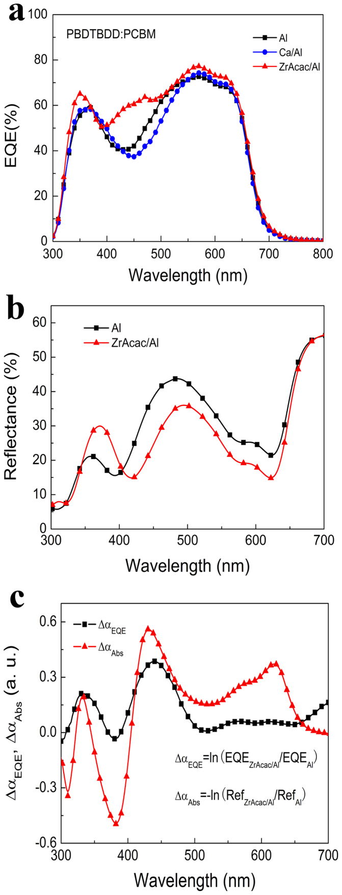
In order to further elucidate the increased Jsc for the devices with a-ZrAcac CBL, we compared the external quantum efficiency (EQE) spectra of the PSCs with Al, Ca/Al and a-ZrAcac/Al cathodes, as given in Figure 5(a) (PBDTBDD:PC60BM based devices) and Figure S7 (P3HT:PC60BM based devices) in SI. As shown in Figure 5(a), in comparison with the devices with Al and Ca/Al cathode, the EQE spectra of PSCs based on PBDTBDD:PCBM with a-ZrAcac CBL exhibits enhanced light response in the whole absorption band of 300–700 nm, giving a notable enhancement in wavelength range from 380 nm to 500 nm, where it is a deep valley for the devices with Al and Ca/Al cathode due to the limited absorption of the polymer as shown in Figure S8 in SI.
Figure 5.
(a) External quantum efficiency (EQE) spectra, and (b) the reflectance spectra of the PSCs based on PBDTBDD:PC60BM with different cathode; (c) the additional absorption spectrum as well as additional EQE spectrum calculated from the difference of reflectance spectra and EQE spectra of the PSCs based on PBDTBDD:PC60BM with a-Zracac/Al and Al cathode, respectively.
To further clarify the different light response behavior, we measured the reflectance spectra of the devices with Al and a-ZrAcac/Al cathode. As shown in Figure 5(b), the reflectance of the device with a-ZrAcac/Al cathode is lower than that of the device with only Al cathode in the wavelength range of 400–650 nm. Actually, the highly transparent characteristic and appropriate thickness of the a-ZrAcac layer could be its advantage on the reflectance over Ca or other organic CBL. To investigate the relationship between the enhanced light harvest (reduced light reflectance) and the increased EQE values (photocurrent response), we derived the additional absorption, ΔαAbs, and the additional EQE, ΔαEQE, from the reflectance and the EQE spectra, respectively, where ΔαAbs = −ln(RefZracac/Al/RefAl), and ΔαEQE = −ln(EQEZracac/Al/EQEAl. Figure 5(c) shows the ΔαAbs and ΔαEQE curves as the function of wavelength. It can be seen that the shape of ΔαEQE curve is very similar to that of the ΔαAbs curve, indicating that the enhanced photocurrent in the device with a-ZrAcac/Al cathode can be mainly ascribed to the additional absorption of the photoactive layer in the device.
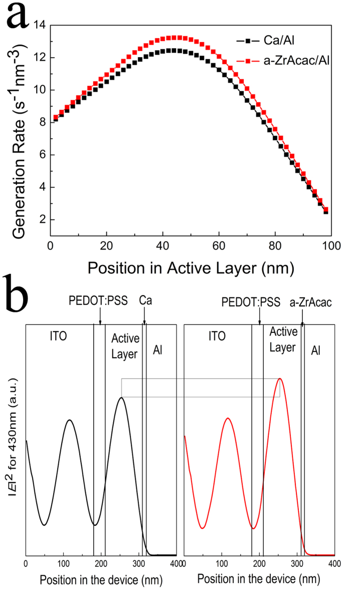
To gain further insight into the origin of the enhanced Jsc in the device, one-dimensional transfer matrix formalism53 based on optical modelling calculations was conducted, where experimentally measured refractive indices and extinction coefficients were used. The exciton generation rate versus position in the PBDTBDD:PC60BM active layer (100 nm) is shown in Figure 6(a) for devices with Ca/Al and a-ZrAcac/Al cathode, verifying that the device with a-ZrAcac/Al cathode can generate more carriers than that of the Ca/Al based device, which accounts in part for the higher Jsc of the device with a-ZrAcac/Al cathode. The calculated exciton generation rate is in good agreement with EQE measurement as shown in Figure 5(a). The normalized modulus of the optical electric field is shown in Figure 6(b) for the PSCs with an active layer thickness of 100 nm and with Ca/Al and a-ZrAcac/Al cathode for a wavelength of 430 nm. This wavelength has been chosen as the difference in EQE, and absorption between the two device stacks is most prominent at 430 nm. Modified with a-ZrAcac causes little shift of the maximum of the electric field but greatly increases the overall modulus throughout the whole active layer. The calculated results of enhanced light distribution within the active layer for a-ZrAcac based device is in agreement with tested reflection spectra as shown in Figure 5(b).
Figure 6.
(a) Modeled exciton generation rate in the PBDTBDD:PC60BM active layer (100 nm) as a function of position within the active layer with Ca/Al and a-ZrAcac/Al cathode. (b) Calculated distribution of the normalized modulus squared of the optical electric field |E2| inside a photovoltaic device: ITO (~180 nm)/PEDOT (~30 nm)/PBDTBDD:PC60BM (~100 nm)/Ca (10 nm) or a-ZrAcac (11 nm)/Al (90 nm) for a wavelength of 430 nm.
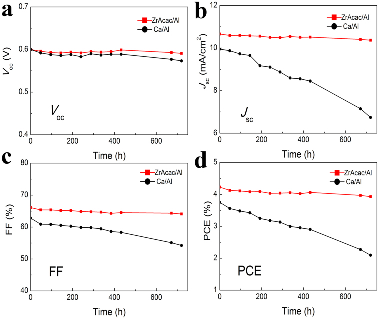
The long term stability of non-encapsulated P3HT:PC60BM based PSCs with a-ZrAcac/Al and Ca/Al cathodes were investigated by testing the evolution of the characteristic parameters (Voc, Jsc, FF, and PCE) with time in a nitrogen filled glove-box (the concentration of H2O and O2 is less than 20 ppm) as shown in Figure 7. After 720 hours (30 days), the PCEs of the devices with Ca/Al drop to about 56% of the initial PCEs. The observed decrease in the PCE is mainly due to a deterioration of both Jsc and FF, with a little drop (5%) of Voc. On the contrary, the devices with a-ZrAcac/Al cathodes were found to show dramatically improved stability and after 30 days retained 93% of its initial PCE under N2. This is in excellent agreement with the stability of PSCs using solution processed PFN layers reported previously32. These results indicate that the a-ZrAcac interfacial layer can effectively improve the long term stability of PSCs.
Figure 7. Long-term stability of the P3HT:PC60BM based PSCs with Ca/Al or a-ZrAcac/Al cathode.
The evolution of (a) Voc, (b) Jsc, (c) FF, and (d) PCE with time. The devices were stored in an N2 filled glove-box.
In summary, we successfully demonstrate high performance PSCs by employing as-prepared ZrAcac film spin-cast from its ethanol solution as CBL. The devices with a-ZrAcac/Al cathode show decreased series resistance and enhanced photocurrent due to the remarkable improvement of the charge extraction and light harvesting. The PCE of the device based on P3HT:PC60BM with a-ZrAcac CBL reaches 4.23% under the illumination of AM1.5G 100 mW/cm2. When choosing D-A copolymer PBDTBDD as electron donor, an average PCE of 8.75% and a best PCE of 9.23% was achieved, which is greatly improved (19% enhancement) in comparison with that (7.34%) of the device with traditional Ca/Al cathode. Our findings indicate that a-ZrAcac is a promising CBL for the fabrication of large area flexible PSCs.
Methods
Device fabrication and characterization
The ITO glass (sheet resistance:10 Ω/sq, CSG Holding, China) was sequential ultrasonic cleaned in detergent, deionized water, acetone, and isopropanol, and then treated in an ultraviolet-ozone chamber (Jelight, USA) for 20 min. PEDOT:PSS (Clevious P VP AI 4083, H. C. Stark) aqueous solution was filtered through a 0.45 μm filter and spin-coated at 2000 rpm for 60 s on the pre-treated ITO substrate, followed by 150°C baking for 10 min in air, achieving a 30 nm thick PEDOT:PSS layer. Subsequently, the PEDOT:PSS modified substrate was transferred to a nitrogen-filled glove-box for photoactive layer and cathode buffer layer preparation. The P3HT (Rieke Metals) and PC60BM or PC70BM (Nano-C) blend layer was prepared by spin-coating (800 rpm) the 1, 2-dichlorobenzene (ODCB) solution of P3HT and PC60BM or PC70BM (1:1 w/w, polymer concentration of 20 mg/mL) on the PEDOT:PSS modified ITO electrode for 20 s, followed by solvent-annealing54 in covered glass Petri dish, obtaining a 240 nm thick photoactive layer. The PBDTBDD and PC60BM blend photoactive layer was prepared by spin-coating (1200 rpm) the dichlorobenzene solution of the mixed solution (1:1 w/w, polymer concentration of 15 mg/mL) with 3% volume ratio of 1,8-Diiodooctane (DIO, Sigma Aldrich) on the PEDOT:PSS modified ITO electrode. The thickness of the photoactive layer is about 100 nm. The PBT1:PC70BM blend photoactive layer was prepared by spin-coating (800 rpm) the ODCB solution of the mixed solution (1:1 w/w, polymer concentration of 10 mg/mL) with 1% volume ratio of DIO on the PEDOT:PSS modified ITO electrode for 60 s, obtaining a ca. 80 nm thick film. The PBDTTT-C-T:PC70BM blend film was fabricated by spin-coating (1500 rpm) the ODCB solution of the mixed solution (1:1.5 w/w, polymer concentration of 12.5 mg/mL) with 3 vol% DIO on the ITO/PEDOT:PSS electrode for 60 s, yielding a ca. 80 nm thick photoactive layer. The ZrAcac powder was bought from Alfa Aesar with a purity of 98%. The ZrAcac ethanol solution was simply made by adding the ZrAcac powder into the anhydrous ethanol solvent then stirred for 3 h, obtaining a colorless solution with concentration of 0.25–2 mg/mL. The ZrAcac cathode buffer layer was prepared by directly spin-coating (1500–6000 rpm) the ZrAcac ethanol solution on the photoactive layer for 60 s to obtain the film with different thickness, no any additional thermal annealing or post-treatment was performed. The just prepared ZrAcac thin layer named as a-ZrAcac layer. Finally, the substrate was transferred to a vacuum chamber and the metal cathode (Al or Ca/Al) was thermally deposited. The photoactive area of the device is around 4 mm2 defined by perpendicular ITO and cathode electrode. The current density–voltage (J–V) and the external quantum efficiency measurements were conducted according to our previous publication30.
Instrumentation
The surface morphologies of the P3HT:PC60BM and PBDTBDD:PC60BM photoactive layers with and without ZrAcac layer were analyzed using a VEECO DICP-II atomic force microscope (AFM) operated in the tapping mode under ambient atmosphere at room temperature. The reflectance spectra were measured by LAMBDA 950 UV/Vis/NIR Spectrophotometer with the device structures of ITO/PEDOT:PSS/PBDTBDD:PC60BM/Al and ITO/PEDOT:PSS/PBDTBDD:PC60BM/a-ZrAcac/Al. The thickness of the photoactive layer was measured by Ambios Technology XP-2 surface profilometer. An ESCA Lab220i-XL electron spectrometer from VG Scientific using 300 W Al K α radiation operated at a base pressure of 3 × 10⁻⁹ mbar was used to obtain XPS data. The binding energies were referenced to adventitious carbon (C 1 s line at 284.8 eV). The ultraviolet photoelectron spectroscopy (UPS) measurements were conducted in ultra-high vacuum (3.0 × 10⁻⁸ Torr) with a Kratos Axis Ultra DLD ultraviolet photoelectron spectrometer equipped with a monochromatic He ultraviolet source He I (hν = 21.22 eV). To separate the sample and the secondary edge for the analyzer, a sample bias of −9 V was applied. The optical constants of a-ZrAcac and the photoactive blend were derived from spectroscopic ellipsometry by SENTECH SE400 rotating compensator ellipsometer.
Author Contributions
Z.A.T., S.S.L., J.L. and Y.F.L. designed, fabricated and characterized the devices. D.P.Q. and J.H.H. synthesized the polymer PBDTBDD. Z.A.T. and F.Z.W. conducted the optical simulation. All authors discussed the results, and Z.A.T., S.S.L. and Y.F.L. write the manuscript.
Supplementary Material
Supporting Information
Acknowledgments
The work was supported by the NSFC (Nos. 21004019, 51173040, 91023039, 51303052, 91333204), the Ministry of Science and Technology of China (973 project, No. 2014CB643501 and 863 project, No. 2011AA050523), the Beijing NOVA Program (No. 2010B038), SRFDP (No.20100036120007), Program for New Century Excellent Talents in University (NCET-12-0848), the 111 Project (B12034), and Fundamental Research Funds for the Central Universities, China (11QG18, 13ZD11).
References
- Sariciftci N. S., Smilowitz L., Heeger A. J. & Wudl F. Photoinduced electron transfer from a conducting polymer to buckminsterfullerene. Science 258, 1474–1476 (1992). [DOI] [PubMed] [Google Scholar]
- Li Y. F. Molecular design of photovoltaic materials for polymer solar cells: Toward suitable electronic energy levels and broad absorption. Acc. Chem. Res. 45, 723–733 (2012). [DOI] [PubMed] [Google Scholar]
- Chen J. & Cao Y. Development of novel conjugated donor polymers for high-efficiency bulk-heterojunction photovoltaic devices. Acc. Chem. Res. 42, 1709–1718 (2009). [DOI] [PubMed] [Google Scholar]
- Gunes S., Neugebauer H. & Sariciftci N. S. Conjugated polymer-based organic solar cells. Chem. Rev. 107, 1324–1338 (2007). [DOI] [PubMed] [Google Scholar]
- Scharber M. C. et al. Design rules for donors in bulk-heterojunction solar cells—Towards 10% energy-conversion efficiency. Adv. Mater. 18, 789–794 (2006). [Google Scholar]
- Li G., Zhu R. & Yang Y. Polymer solar cells. Nat. Photonics 6, 153–161 (2012). [Google Scholar]
- Ma H. Yip H.-L., Huang F. & Jen A. K.-Y. Interface engineering for organic electronics. Adv. Funct. Mater. 20, 1371–1388 (2010). [Google Scholar]
- Steim R., Kogler F. R. & Brabec C. J. Interface materials for organic solar cells. J. Mater. Chem. 20, 2499–2512 (2010). [Google Scholar]
- Chen L.-M., Hong Z., Li G. & Yang Y. Recent progress in polymer solar cells: manipulation of polymer:fullerene morphology and the formation of efficient inverted polymer solar cells. Adv. Mater. 21, 1434–1449 (2009). [Google Scholar]
- Brabec C. J. et al. Origin of the open circuit voltage of plastic solar cells. Adv. Funct. Mater. 11, 374–380 (2001). [Google Scholar]
- Jørgensen M., Norrman K. & Krebs F. C. Stability/degradation of polymer solar cells. Sol. Energ. Mat. Sol. C. 92, 686–714 (2008). [Google Scholar]
- Kawano K. et al. Degradation of organic solar cells due to air exposure. Sol. Energ. Mat. Sol. C. 90, 3520–3530 (2006). [Google Scholar]
- Norrman K., Gevorgyan S. A. & Krebs F. C. Water-induced degradation of polymer solar cells studied by H218O labeling. ACS Appl. Mater. Interfaces 1, 102–112 (2009). [DOI] [PubMed] [Google Scholar]
- Voroshazi E. et al. Influence of cathode oxidation via the hole extraction layer in polymer:fullerene solar cells. Org. Electron. 12, 736–744 (2011). [Google Scholar]
- Brabec C. J., Shaheen S. E., Winder C., Sariciftci N. S. & Denk P. Effect of LiF/metal electrodes on the performance of plastic solar cells. Appl. Phys. Lett. 80, 1288 (2002). [Google Scholar]
- Li G., Chu C.-W., Shrotriya V., Huang J. & Yang Y. Efficient inverted polymer solar cells. Appl. Phys. Lett. 88, 253503 (2006). [Google Scholar]
- Liao H.-H., Chen L.-M., Xu Z., Li G. & Yang Y. Highly efficient inverted polymer solar cell by low temperature annealing of Cs2CO3 interlayer. Appl. Phys. Lett. 92, 173303 (2008). [Google Scholar]
- Yip H.-L., Hau S. K., Baek N. S., Ma H. & Jen A. K.-Y. Polymer solar cells that use self-assembled-monolayer- modified ZnO/metals as cathodes. Adv. Mater. 20, 2376–2382 (2008). [Google Scholar]
- Yip H. L., Hau S. K., Baek N. S. & Jen A. K. Y. Self-assembled monolayer modified ZnO/metal bilayer cathodes for polymer/fullerene bulk-heterojunction solar cells. Appl. Phys. Lett. 92, 193313 (2008). [Google Scholar]
- Kim J. Y. et al. Solution-processable zinc oxide for the polymer solar cell based on P3HT:PCBM. Nanosci. Nanotechnol. 11, 5995–6000 (2011). [DOI] [PubMed] [Google Scholar]
- Jo S. B. et al. High performance organic photovoltaic cells using polymer-hybridized ZnO nanocrystals as a cathode interlayer. Adv. Energy Mater. 1, 690–698 (2011). [Google Scholar]
- Kim J. Y. et al. New architecture for high-efficiency polymer photovoltaic cells using solution-based titanium oxide as an optical spacer. Adv. Mater. 18, 572–576 (2006). [Google Scholar]
- Park S. H. et al. Bulk heterojunction solar cells with internal quantum efficiency approaching 100%. Nat. Photonics 3, 297–302 (2009). [Google Scholar]
- Sun Y. et al. Efficient, air-stable bulk heterojunction polymer solar cells using MoOx as the anode interfacial layer. Adv. Mater. 23, 2226–2230 (2011). [DOI] [PubMed] [Google Scholar]
- Salim T. et al. Solution-processed nanocrystalline TiO2 buffer layer used for improving the performance of organic photovoltaics. ACS Appl. Mater. Interfaces 3, 1063–1067 (2011). [DOI] [PubMed] [Google Scholar]
- Tan Z. A., Yang C. H., Zhou E. J., Wang X. & Li Y. F. Performance improvement of polymer solar cells by using a solution processible titanium chelate as cathode buffer layer. Appl. Phys. Lett. 91, 023509 (2007). [Google Scholar]
- Wang F. Z. et al. Alcohol soluble titanium(IV) oxide bis(2,4-pentanedionate) as electron collection layer for efficient inverted polymer solar cells. Org. Electron. 13, 2429–2435 (2012). [Google Scholar]
- Zhang W. Q. et al. ITO electrode/photoactive layer interface engineering for efficient inverted polymer solar cells based on P3HT and PCBM using a solution-processed titanium chelate. J. Phys. D: Appl. Phys. 45, 285102 (2012). [Google Scholar]
- Wang F. Z. et al. Improved performance of polymer solar cells based on P3HT and ICBA using alcohol soluble titanium chelate as electron collection layer. Org. Electron. 14, 845–851 (2013). [Google Scholar]
- Tan Z. A. et al. High-performance inverted polymer solar cells with solution-processed titanium chelate as electron-collecting layer on ITO electrode. Adv. Mater. 24, 1476–1481 (2012). [DOI] [PubMed] [Google Scholar]
- He Z. et al. Simultaneous enhancement of open-circuit voltage, short-circuit current density, and fill factor in polymer solar cells. Adv. Mater. 23, 4636–4643 (2011). [DOI] [PubMed] [Google Scholar]
- He Z. et al. Enhanced power-conversion efficiency in polymer solar cells using an inverted device structure. Nat. Photonics 6, 591–595 (2012). [Google Scholar]
- Lv M. et al. A hyperbranched conjugated polymer as the cathode interlayer for high-performance polymer solar cells. Adv. Mater. 25, 6889–6894 (2013). [DOI] [PubMed] [Google Scholar]
- Tokmoldin N., Griffiths N., Bradley D. D. C. & Haque S. A. A hybrid inorganic–organic semiconductor light-emitting diode using ZrO2 as an electron-injection layer. Adv. Mater. 21, 3475–3478 (2009). [Google Scholar]
- Park J. S. et al. High performance polymer light-emitting diodes with N-type metal oxide/conjugated polyelectrolyte hybrid charge transport layers. Appl. Phys. Lett. 99, 163305 (2011). [Google Scholar]
- Vasilopoulou M. et al. Atomic layer deposited zirconium oxide electron injection layer for efficient organic light emitting diodes. Org. Electron. 14, 312–319 (2013). [Google Scholar]
- Li Q., Zhong X., Hu J. & Kang W. Preparation and corrosion resistance studies of zirconia coating on fluorinated AZ91D magnesium alloy. Prog. Org. Coat. 63, 222–227 (2008). [Google Scholar]
- Loukova G. V., Huhn W., Vasiliev V. P. & Smirnov V. Ligand-to-metal charge transfer excited states with unprecedented luminescence yield in fluid solution. J. Phys. Chem. A 111, 4117–4121 (2007). [DOI] [PubMed] [Google Scholar]
- Stary J. & Liljenzin J. O. Critical evaluation of equilibrium constants involving acetylacetone and its metal chelates. Pure Appl. Chem. 54, 2557–2592 (1982). [Google Scholar]
- Ismail H. M. Characterization of the decomposition products of zirconium acetylacetonate: nitrogen adsorption and spectrothermal investigation. Powder Technol. 85, 253–259 (1995). [Google Scholar]
- Hou J. et al. Synthesis and photovoltaic properties of two-dimensional conjugated polythiophenes with bi(thienylenevinylene) side chains. J. Am. Chem. Soc. 128, 4911–4916 (2006). [DOI] [PubMed] [Google Scholar]
- Qian D. et al. Design, application, and morphology study of a new photovoltaic polymer with strong aggregation in solution state. Macromolecules 45, 9611–9617 (2012). [Google Scholar]
- Qian D. et al. Molecular design toward efficient polymer solar cells with high polymer content. J. Am. Chem. Soc. 135, 8464–8467 (2013). [DOI] [PubMed] [Google Scholar]
- Tan Z. et al. Solution-processed rhenium oxide: a versatile anode buffer layer for high performance polymer solar cells with enhanced light harvest. Adv. Energy Mater. 4, 1300884 (2014). [Google Scholar]
- He Y., Chen H.-Y., Hou J. & Li Y. Indene−C60 bisadduct: a new acceptor for high-performance polymer solar cells. J. Am. Chem. Soc. 132, 1377–1382 (2010). [DOI] [PubMed] [Google Scholar]
- Tan Z. et al. solution-processed tungsten oxide as an effective anode buffer layer for high-performance polymer solar cells. J. Phys. Chem. C 116, 18626–18632 (2012). [Google Scholar]
- Yip H.-L. & Jen A. K.-Y. Recent advances in solution-processed interfacial materials for efficient and stable polymer solar cells. Energy Environ. Sci. 5, 5994–6011 (2012). [Google Scholar]
- Ma W., Yang C., Gong X., Lee K. & Heeger A. J. Thermally stable, efficient polymer solar cells with nanoscale control of the interpenetrating network morphology. Adv. Funct. Mater. 15, 1617–1622 (2005). [Google Scholar]
- Barreca D. et al. Zirconium Dioxide Thin Films Characterized by XPS. Surf. Sci. Spectra 7, 303–309 (2000). [Google Scholar]
- Lung C., Kukk E., Hägerth T. & Matinlinna J. Surface modification of silica-coated zirconia by chemical treatments. Appl. Surf. Sci. 257, 1228–1235 (2010). [Google Scholar]
- Wilkinson G., Gillard R. D. & McCleverty A. Comprehensive coordination chemistry: The synthesis, reactions, properties & applications of coordination compounds. Pergamon Press 1987. [Google Scholar]
- Palmer D. M., Straughan B. P. & Treverton J. A. XPS studies of zirconium complexes on polymer surfaces. Appl. Surf. Sci. 68, 243–250 (1993). [Google Scholar]
- Pettersson L. A. A., Lucimara S. R. & Inganas O. Modeling photocurrent action spectra of photovoltaic devices based on organic thin films. J. Appl. Phys. 86, 487–496 (1999). [Google Scholar]
- Li G. et al. High-efficiency solution processable polymer photovoltaic cells by self-organization of polymer blends. Nat. Mater. 4, 864–868 (2005). [Google Scholar]
Associated Data
This section collects any data citations, data availability statements, or supplementary materials included in this article.
Supplementary Materials
Supporting Information


