Abstract
This paper presents an ungrounded, hand-held surgical device that incorporates active constraints and force-feedback. Optical tracking of the device and embedded actuation allow for real-time motion compensation of a surgical tool as an active constraint is encountered. The active constraints can be made soft, so that the surgical tool tip motion is scaled, or rigid, so as to altogether prevent the penetration of the active constraint. Force-feedback is also provided to the operator so as to indicate penetration of the active constraint boundary by the surgical tool. The device has been evaluated in detailed bench tests to quantify its motion scaling and force-feedback capabilities. The combined effects of force-feedback and motion compensation are demonstrated during palpation of an active constraint with rigid and soft boundaries. A user study evaluated the combined effect of motion compensation and force-feedback in preventing penetration of a rigid active constraint. The results have shown the potential of the device operating in an ungrounded setup that incorporates active constraints with force-feedback.
I. Introduction
Surgical robots are designed to enhance a surgeon’s dexterity and sensory feedback whilst allowing the surgeon to have full control of the operation. This has been achieved through accurate articulation of the surgical device as well as incorporating features such as motion scaling and tremor removal. Some of these features have already been implemented on master-slave systems and cooperatively-controlled robotic platforms. Cooperatively-controlled systems such as the Steady-Hand robot [1], for example, allow the operator and robotic manipulator to hold the surgical tool together. The Steady-Hand robot suppresses erroneous tool motion and provides force-feedback during microsurgical tasks. These grounded systems can also use magnetically-levitated wrists to achieve motion scaling and force-feedback of a surgical tool [2]. As an alternative to cooperatively-controlled robots, ungrounded hand-held devices can have a smaller physical footprint, are less obtrusive to manipulate and can be integrated into the surgical workflow with greater ease.
Micron is a hand-held motion compensation device that has been designed to correct erroneous motion caused by the physiological tremor of the operator [3]. Such systems are intended for delicate micromanipulation tasks, for example in retinal surgery [4] or cell manipulation [5]. Typically, hand-held ungrounded tremor suppression is achieved through optical tracking [6] or inertial sensing [7] of the hand-held device. Actuators are then used to move the tool tip in the opposing direction to the sensed disturbance. As well as tremor suppression, these devices have been used to perform semi-automatic functions, such as targeting of the instrument tool tip [8]. More recently, this approach has been further developed to achieve increased loading, dexterity and workspace [9]. Whilst these systems are capable of cancelling tremor, the travel range of the actuators limits their use for compensating larger scale motions outside of microsurgical tasks, which, for example, can be caused by physiological motion of the patient.
Thus far, a number of force control-based motion-compensation schemes have been investigated for steady tissue contact of a high magnification optical probe [10] and force tracking in beating heart surgery [11]. These systems work by employing a force-control scheme that ensures the probe or tool is kept in contact with the organ at a prescribed force level. These systems, however, require direct physical contact and can only work as long as the instrument is in contact with the organ being tracked. This approach is unsuitable when a region of anatomy is to be avoided altogether.
Active constraints or virtual fixtures allow ‘no-go’ areas during surgical navigation [12]. These can be implemented so as to guide the tool along or away from certain anatomical areas [13], [14]. This principle has been adopted extensively in orthopedic applications [15]. Active constraints have mainly been applied to grounded, cooperatively-controlled robotic systems, for example, the Sculptor RGA (Stanmore Implants, Elstree, UK.), MAKOplasty® (MAKO Surgical Corp., FL, USA) and the Steady-Hand robot [14]. These grounded robotic platforms use haptic feedback to guide the operator along or away from the active constraint. However, the application of active constraints to ungrounded, hand-held instruments requires an alternative approach. Active constraints have been implemented on Micron so that the instrument tip’s position is constrained so as to not deviate from a pre-programmed trajectory [16]. The application of active constraints significantly improves tool tip accuracy in micromanipulation tasks; however there is no force-feedback to the operator that indicates tool interaction with the active constraint. The provision of force-feedback is an inherent problem of ungrounded hand-held devices as they do not have mechanical links through which reaction forces can be transmitted.
Recently, hand-held, ungrounded force-feedback systems have been developed in order to provide force-feedback without necessitating cumbersome robotic arm assemblies. These devices have been designed to scale up the small forces in micromanipulation to levels that are better perceived by the human-scale sense of touch. Stetten et al. developed a force-magnifying hand-held device that exerted forces on the operator by exerting the reaction force through a bracing attached to the operator’s wrist [17]. This device was then evolved to incorporate improved force-sensing that could magnify both push and pull forces of the surgical tool [18]. Another ungrounded, hand-held force-amplifying device could display force-feedback on to the operator’s fingertip, forgoing the need for bracing or anchoring mechanisms [19]. Ungrounded force-feedback has also been implemented with virtual environments in which a haptic pen could exert forces on to the operator [20].
The purpose of this paper is to present an ungrounded, hand-held device that combines motion compensation and force-feedback of a surgical tool for interaction with active constraints. The motion compensation scheme provides a position constraint on the surgical tool whilst the force-feedback allows for tactile interaction with the active constraint. This technique could allow for surgical tools to be guided through safe channels with less cognitive burdening of the operator. It is envisaged that such a device has potential applications in Neurosurgery, Otorhinolaryngology and Pediatric surgery, in which surgeons must operate around delicate anatomical areas within tight spatial constraints and with restricted vision. The proposed device is validated in detailed bench tests and user studies to verify the motion compensation and force-feedback capabilities of the device, with results demonstrating its potential clinical value.
II. Conceptual Overview and Engineering Design
A. Conceptual Overview
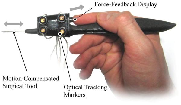
The device is designed to be held as a stylus by the operator with a surgical tool protruding from the tip as shown in Fig. 1. The surgical tool can be actuated along its axis so as to retract into the stylus as it encounters an active constraint. A force-feedback display exerts forces on to the operator’s fingertip when the active constraint is penetrated. An Optotrak Certus (Northern Digital Inc, Ontario, Canada) optical tracking system is used in order to locate the device’s position and orientation with respect to the active constraint. The optical tracking system is capable of achieving sub-millimeter resolution and operates at acquisition speeds in excess of 1kHz.
Fig. 1.
A photograph of the hand-held device illustrating its key features of motion compensation and force-feedback.
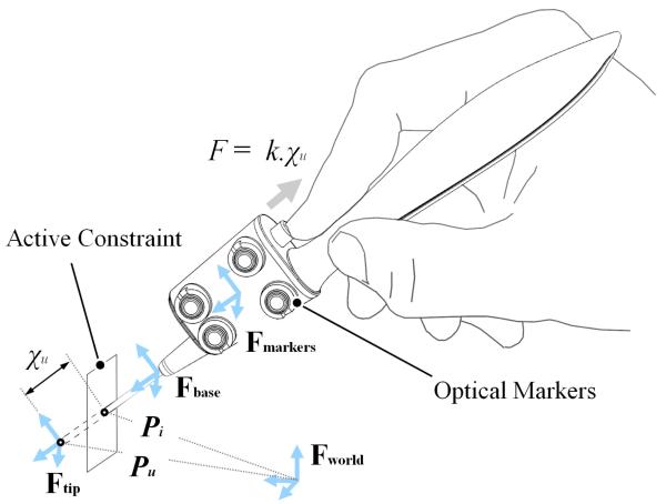
Four optical markers are attached to the casing of the device and are tracked by the optical tracking system. As shown in Fig. 2, a rigid body co-ordinate system is defined at the origin of the optical markers {Fmarkers} which is known with respect to a world co-ordinate system {Fworld} defined by the optical tracking system. A series of rigid transformations are computed in order to obtain coordinate systems at the base of the surgical tool {Fbase} and at the uncompensated tool tip {Ftip}. The origin of co-ordinate system {Ftip} is the uncompensated surgical tool position Pu. This is the tool tip position when the tool is fully advanced from the stylus and is always fixed relative to {Fbase}. The vector between coordinate systems {Fbase} and {Ftip} represents the axis of the surgical tool. An active constraint surface is also defined in the world coordinate system so that when the uncompensated tool-tip Pu moves beyond the active constraint surface, a theoretical penetration distance is computed and defined as χu. This is the distance between Pu and the point of intersection between the active constraint surface and the axis of the tool, defined as Pi. The actuator then retracts the tool in proportion to the penetration distance χu by a factor of Ks. The tool can be retracted by the same distance as χu so that it does not go beyond the active constraint, thus providing an infinitely rigid position constraint (Ks = 1). Alternatively, the tool can be retracted by a fraction of χu so that the tip motion is scaled, forming a ‘soft constraint’ (where 0 < Ks < 1). For the proposed device, the operator’s index finger is placed onto a translatable slider that exerts a force of magnitude F that is directly proportional to χu by a factor k so as to provide a spring-like force-feedback response. This translatable slider-based configuration is first proposed in [19][18]. The stiffness parameter k can be varied so that the operator can feel the active constraint to have different stiffness properties.
Fig. 2.
A schematic diagram showing the locations of all the co-ordinate systems from the world to the uncompensated tool tip and how the penetration distance is defined for the motion compensation. Force-feedback to the user is proportional to the penetration distance.
B. Hardware Design and Control Scheme
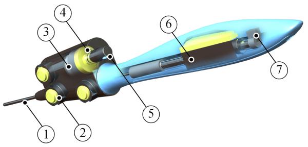
A linear motor (LM) (LM0830-015-01, Faulhaber) was used to actuate the surgical tool, thus providing the motion compensation. This motor was chosen for its compact size, response time, integrated position sensing and appropriate stroke length of 15mm. The magnetic shaft of the motor is co-axially mounted to the surgical tool using a coupling mechanism. An anti-rotation keyway feature is mounted onto the opposite end of the magnetic shaft. It is seated in a groove and prevents axial rotation of the surgical tool. A voice coil actuator (VCA) (LVCM-013-013-02, Moticont) was used to actuate the force-feedback display. It was chosen for its compact size relative to the peak force it can generate and its simple controllability. It has a total stroke length of 6.4mm, which is acceptable for applying loads to the fingertip of the operator. A force sensor (8438 5005, Burster) is mounted between the VCA and the force-feedback display and is used to provide closed-loop force control. These features are illustrated in Fig. 3.
Fig. 3.
A ghosted CAD rendering of the hand-held the device showing: (1) the surgical tool (2) the optical tracking markers (3) voice coil actuator (4) force sensor (5) force-feedback display (6) linear motor and (7) anti rotation feature.
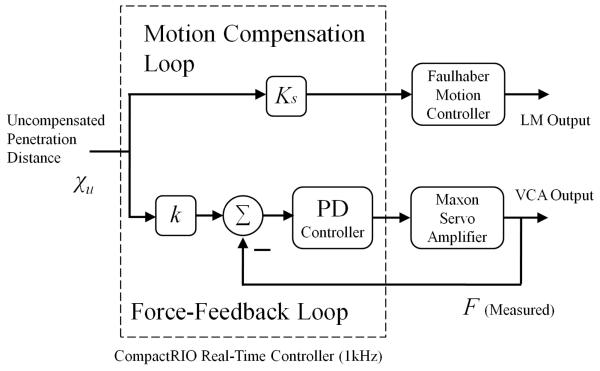
The coordinates of the optical markers are passed to the Optotrak Certus acquisition hardware. A standard PC with a quad-core Intel® processor is used to receive and process the coordinate data. The active constraint is simulated in a C/C++ programming environment in order to calculate the value of the uncompensated penetration distance χu. This value is then passed to a multi-threaded real-time controller (CompactRIO, cRIO-9014, National Instruments Corp.) running at 1kHz through a User Datagram Protocol (UDP) connection. The uncompensated penetration distance is then multiplied by the motion scaling factor Ks. The CompactRIO controller then outputs an analogue voltage to the LM controller (MCLM 3006S, Faulhaber) which controls the position of the LM using its own low-level position control loop. The uncompensated tool tip penetration distance χu is also fed in to a force control algorithm which controls the magnitude of force that the VCA exerts on to the operator’s fingertip. The distance χu is multiplied by the force-feedback stiffness parameter k in order to generate a desired force set-point. The force sensor mounted between the VCA and the operator’s fingertip measures the actual force being exerted. The error between the desired force input and the measured force output is fed in to a Proportional-Derivative (PD) controller implemented on the FPGA of the CompactRIO. The output from the PD controller is fed in to an amplifier (LSC 30/2 linear 4Q Servoamplifier, Maxon) that controls the power provided to the VCA. These control loops are shown in Fig. 4.
Fig. 4.
A control block diagram showing the parallel control loops implemented on the CompactRIO responsible for the motion compensation of the tool tip and the force-feedback to the operator.
III. Experiments
A. Bench Tests
The device was evaluated in a series of bench tests in order to quantify its motion compensation and force-feedback abilities. A second rigid body containing four optical markers was attached to the surgical tool shaft so as to allow a calculation of the actual tool tip position Pa using a rigid transformation from the origin of the four additional optical markers. An initial calibration was performed in order to co-align points Pa with Pu in the world coordinate system before the experiments took place. This was done by placing the device in a jig with known geometry and zeroing the tool position when it was fully advanced. The measured distance that the tool tip had actually penetrated the active constraint χa was calculated as being the distance between Pa active constraint intersection point Pi.
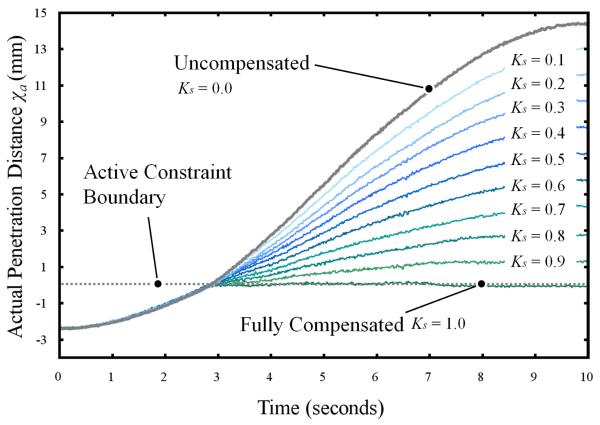
The device was rigidly clamped to a test rig that excited the device linearly along the axis of the surgical tool. The device was excited with a sinusoidal input at 0.05Hz through a peak-to-peak amplitude of 16.6mm using a linear motor (LM1247-040-01, Faulhaber). An active constraint was positioned 2.5 mm in front of the tool tip and the measurements of χa were made over time, this is shown in Fig. 5. The device was programmed to retract the instrument tool tip for 10 scaling factors of χu at 0.1 intervals between 0-1. Additionally, the device was excited with the tool rigidly fixed so as to show the trajectory of the uncompensated instrument (equivalent to the trajectory of χu) for comparison. The hand-held device was excited to an amplitude within the maximum stroke of the linear motor, which ensures there were no discontinuities in the motion compensation as a result of the actuation range of the device.
Fig. 5.
A plot showing actual penetration distance of the tool tip versus time for the fully compensated, uncompensated and 9 motion-scaled cases.
For each case, the trajectory starts at 2.5mm from the active constraint; the penetration distance is defined as negative when the surgical tool is approaching the active constraint. When the surgical tool penetrates the active constraint, a discontinuity in its trajectory is observed for all but the uncompensated cases. When fully compensated, the position of the tip is held constant at the active constraint boundary threshold. A maximum penetration error of 0.13mm was observed for this case. In the motion-scaled cases, the trajectories of the tool tip can be seen as transformed sine profiles following penetration of the active constraint.
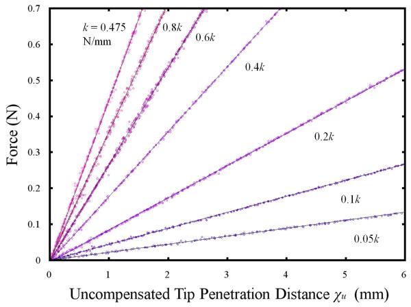
In a second experiment, the device was translated into an active constraint and measurements were made of the forces generated by the force-feedback display with respect to the theoretical distance χu. The device was mounted onto the excitation rig as used in the previous experiment and the force-feedback display was pre-loaded with a spring to simulate the operator’s fingertip. The force sensor was zeroed before each experiment and calibrated against precision weights. Fig. 6. illustrates the force-displacement profiles for 7 settings of k. Linear regression models using the least squares method are fitted to the observed measurements.
Fig. 6.
A plot showing force versus the uncompensated tool tip penetration distance for 7 different stiffness factors.
It has been shown that the device was capable of accurately reproducing a range of stiffness factors which could be used to create rigid and soft constraints as the operator collides the device with an active constraint. A linear relationship between force and uncompensated tip penetration distance is observed. This is true up until the point that the VCA saturates, after which point a discontinuity is introduced into the force-feedback response. At higher stiffness factors, the motors saturate after only a short penetration distance. The current limits set in this experiment meant that the VCA saturated at around 0.8N. The linear regression models fitted to the experimental data showed that the observed values of k were less than the preset value by an average of 5.7%. This can be attributed to the absence of integral control in the force-feedback control scheme.
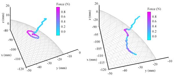
To illustrate the combined motion compensation and force-feedback abilities of the device, a freehand palpation of a spherical active constraint is presented in Fig. 7. This shows an operator interacting with both a rigid (fully motion compensated) and soft (motion scaled, where Ks = 0.5) active constraint. A force-feedback stiffness factor of 0.19N/mm was adopted for the interaction.
Fig. 7.
Plot showing the actual tool tip position Pa in a free hand palpation of a spherical active constraint for both rigid (left) and soft (right) active constraints in which the tool tip motion is fully compensated and scaled respectively.
The color overlay represents the force being exerted on the operator as the active constraint is palpated. In both cases, the tool tip approaches the active constraint with no force being exerted on to the operator. As the uncompensated tool tip position fluctuates, so does the force being exerted onto the operator. When the rigid positional constraint has been implemented, the tool tip motion is constrained to the surface of the spherical active constraint. In the motion-scaled case, it can be seen that the tool trajectory penetrates beyond the constraint boundary in proportion to the motion scaling factor. Additionally, the force-feedback is proportional to the distance penetrated by the surgical tool, so that the operator experiences a spring-like response from the active constraint.
B. User Study
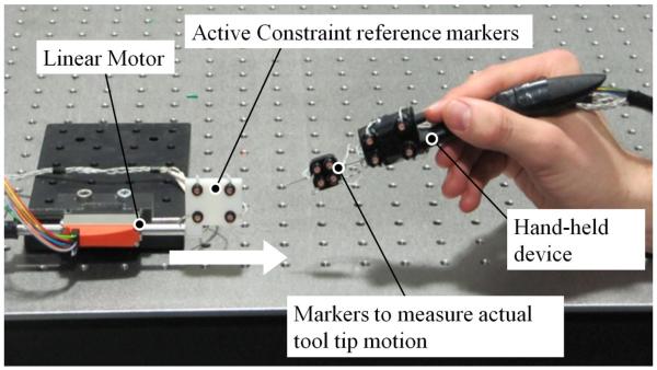
A user study was conducted in order to quantify the performance of the combined motion compensation and force-feedback abilities of the hand-held device with respect to user performance. Eight right-handed users (4 female and 4 male) of ages 24 to 35 with no clinical experience were recruited for this study. The users were asked to hold the hand-held device in a stationary position whilst an active constraint was translated on to the tool tip so as to cause a virtual collision and generate force-feedback on to the user’s fingertip. The experimental setup is shown in Fig. 8.
Fig. 8.
shows the experimental setup. The hand-held device is held stationary by the operator whilst the linear motor translates the active constraint on to the tip of the device so as to cause a collision. The optical markers are tracked using the Optotrak system which is not shown.
The penetration depth threshold at which users could perceive the active constraint was measured when the device was operated with and without the tool tip motion compensation. A fully compensated (rigid) position constraint was imposed for the compensated case in this study. The same hand-held device as used in the bench tests that incorporated the additional optical markers that could track the tool directly was adopted in this user study. An additional rigid body containing optical markers was mounted on to a linear motor (LM1247-040-01, Faulhaber) and translated towards the hand-held device at a constant velocity of 9mm/s towards the tool tip. The linear motor shaft was constrained so as to only allow linear translation of the rigid body containing the optical markers. A constant velocity profile was chosen so that all virtual collisions would occur at the same velocity across the user study and prevent biasing of the results. This would not have been the case if users had instead been requested to translate the device towards a stationary active constraint. Additionally, this would potentially cause users to learn the position of the active constraint through their proprioception sense. The device was positioned to make contact with the translating active constraint at approximately halfway through its stroke.
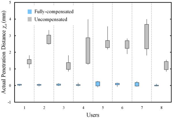
A stiffness factor of k = 0.475N/mm was implemented in the force-feedback control algorithm for both cases. Since the velocity of the active constraint was translated at 9mm/s, neglecting physiological tremor, on average the VCA would reach its peak force 0.19 seconds after the tool tip penetrates the active constraint. This ensured a near instantaneous sensation to the user, which reduced the time for them to perceive the active constraint. Use of a lower stiffness factor would bias the study in favor of the motion-compensated case. The users were required to depress a push button immediately after they felt the force-feedback from the device. For each collision detection, the instantaneous actual penetration depth χa was acquired through a DAQ card (NI-6221, National Instruments Corp., USA) and then passed to the multi-threaded real-time controller (cRIO-9014, National Instruments Corp.) which returned the data to a host PC. The data was logged from the host PC at a rate of 100Hz. The users were required to perform 5 runs for both the compensated and uncompensated cases. The motion compensation was switched on and off randomly between each run without the user’s knowledge so as to prevent biasing of the results. Users were requested to not observe the experiment area so as to be wholly dependent on their sense of touch in perceiving the active constraint. The results of the user study are presented as a box plot in Fig. 9.
Fig. 9.
A box plot showing thresholds for the actual distance penetrated by the tool tip following the user’s indication that they had perceived the active constraint for both fully compensated and uncompensated cases.
It has been shown that the use of motion compensation reduced the actual penetration distance of the tool tip significantly. The average penetration distance for the compensated case was 0.06mm and for the uncompensated case, 2.12mm. The results from these 2 cases were shown to be significant (P = 3.1×10⁻¹⁷) through a statistical comparison test (Kruskal-Wallis). The peak penetration distance measured for the compensated case (0.27 mm) is lower than the lowest measured penetration distance for the uncompensated case (0.83mm). No trends were observed to suggest an improvement in performance over time by the users. Another salient feature of Fig. 9 is the considerable differences in the variability of the measured tool penetration distances, with the motion compensation providing greater consistency. The standard deviations of the penetration compensated case (0.09 mm) and uncompensated case (0.91 mm) highlight this point. These results indicate the ability of the hand-held device to respond faster than its human operator. The variability in the compensated cases can be largely attributed to latency in control of the instrument tool tip. The large variability observed in the uncompensated case can be attributed to a number of human factors, although most significantly, the reaction time in perceiving, cognitively processing the active constraint and mechanically depressing the push button. For this reason, the results observed for the uncompensated case represent an overestimate for the actual penetration depth thresholds that were perceived through the force-feedback display. This is because the active constraint was always advancing towards the tool tip, whereas in the compensated case, the relative motion between active constraint and tool tip could be advancing or receding from the active constraint boundary. For the same reasons, quantization errors in the measurements will also increase the measured penetration distances in the uncompensated case.
In addition to variations in the intrinsic reaction times between users, other factors explain the large variations in the perceived active constraint penetration distance thresholds. Any pre-loading of the force-feedback display will have reduced the fidelity of the tactile sensation felt when the tool tip penetrated the active constraint. The reaction time is also dependent on the concentration of the operator in the instant in which they perceived the active constraint. Differences in the extent of erroneous physiological motion between users may also explain the inter-user variability in both the compensated and uncompensated cases. High amplitude physiological tremor or other high frequency motions cannot be fully compensated for by the control scheme implemented in this study.
Conclusion
In this study, we have proposed a novel ungrounded hand-held device for providing active constraints with force-feedback. The hand-held device has been quantified with respect to its motion compensation and force-feedback abilities in bench tests. It has also been validated in terms of its ability to indicate interaction with an active constraint to a user through a controlled user study. It is expected that this work can be extended to demonstrate tool guidance of an ungrounded, hand-held instrument through pre-defined active constraints. Whilst implementation of active constraints with an ungrounded hand-held device has previously been demonstrated [16], this work demonstrates that force-feedback allows intuitive perception of the active constraint by the user. The force-feedback provides a prompt for the user to indicate when they are in close proximity to an anatomically-critical area. It also has potential to aid navigation of the tool in conjunction with the motion compensation. Additionally, knowledge of the active constraint boundary is important in preventing the operator exceeding the range of the motion compensation.
Future work will investigate the use of force-feedback to aid navigation of an active constraint path. For this to work, it is likely that additional degrees-of-freedom would need to be rendered back to the operator to provide a direction to the tactile cue. Whilst there is merit the simplicity of a single degree-of-freedom motion compensation system, additional degrees-of-freedom of the surgical tool would also enhance performance, for example, when the tool approaches an oblique surface. Whilst force-feedback has been provided in this study, there is also the potential for sensory substitution such as auditory feedback to indicate proximity to an active constraint. This work could also be extended to incorporate dynamic active constraints [21], [22] when physiological motion needs to be compensated for. This would allow autonomous tracking of the tool tip and permit high-level guidance of the instrument through the use of force-feedback.
In summary, we have developed a novel ungrounded, hand-held device that combines motion compensation and force-feedback. It is expected that such a device could be used in surgical scenarios to enhance the safe navigation of surgical tools.
Acknowledgments
The authors would like to acknowledge Hedyeh Rafii-Tari, Valentina Vitiello, Hani Marcus and Thomas Cundy for their contributions to this research.
Research supported in part by a Wates Fellowship and the Wellcome Trust Medical Engineering Centre of Excellence Grant.
References
- [1].Taylor R, Jensen P, Whitcomb L, Barnes A, Kumar R, Stoianovici D, Gupta P, Wang Z, de Juan E, Jr., Kavoussi L. A steady-hand robotic system for microsurgical augmentation. Int. J. Robot. Res. 1999;18:1201–1210. [Google Scholar]
- [2].Salcudean SE, Yan J. Toward a force-reflecting motion-scaling system for microsurgery. Proc. IEEE Int. Conf. Robot. Autom.; May 1994.pp. 2296–2301. [Google Scholar]
- [3].Ang WT, Riviere CN, Khosla PK. An active hand-held instrument for enhanced microsurgical accuracy. Proc. Med. Image Comput. Comput.-Assisted Intervention Conf.; 2000.pp. 878–886. [Google Scholar]
- [4].Becker BC, Voros S, Lobes LA, Handa JT, Hager GD, Riviere CN. Retinal vessel cannulation with an image-guided handheld robot. 32nd Annual International Conference of the IEEE EMBS; Argentina. Aug. 31 – Sep. 4, 2010; [DOI] [PMC free article] [PubMed] [Google Scholar]
- [5].Tabarés JC, MacLachlan R, Ettensohn C, Riviere CN. Cell micromanipulation with an active handheld micromanipulator. Proc. 32nd Annu. Int. Conf. IEEE Eng. Med. Biol. Soc.; Aug./Sep. 2010; pp. 4363–4366. [DOI] [PMC free article] [PubMed] [Google Scholar]
- [6].MacLachlan RA, Becker BC, Cuevas Tabares J, Podnar GW, Lobes LA, Jr., Riviere CN. Micron: an actively stabilized handheld tool for microsurgery. IEEE Trans. on Robotics. 2012 Feb.28(1):195–212. doi: 10.1109/TRO.2011.2169634. [DOI] [PMC free article] [PubMed] [Google Scholar]
- [7].Latt WT, Tan UX, Shee CY, Ang WT. A compact hand-held active physiological tremor compensation instrument. Proc. IEEE/Amer.Soc. Mech. Eng. Int. Conf. Adv. Intell. Mechatronics; Singapore. 14–17 Jul. 2009.pp. 711–716. [Google Scholar]
- [8].Becker BC, et al. Semiautomated intraocular laser surgery using handheld instruments. Lasers Surg. Med. 2010;42:264–273. doi: 10.1002/lsm.20897. [DOI] [PMC free article] [PubMed] [Google Scholar]
- [9].Yang S, MacLachlan RA, Riviere CN. Design and analysis of 6 dof handheld micromanipulator. Proc. IEEE Int. Conf. Robot. Autom.; 2012; pp. 1946–1951. [DOI] [PMC free article] [PubMed] [Google Scholar]
- [10].Latt WT, Newton RC, Visentini-Scarzanella M, Payne CJ, Noonan DP, Shang J, Yang G-Z. A hand-held instrument to maintain steady tissue contact during probe-based confocal laser endomicroscopy. IEEE Transactions on Biomedical Engineering. 2011 Sep.58(9) doi: 10.1109/TBME.2011.2162064. [DOI] [PubMed] [Google Scholar]
- [11].Yuen SG, Perrin DP, Vasilyev NV, del Nido PJ, Howe RD. Force tracking with feed-forward motion estimation for beating heart surgery. IEEE Transactions on Robotics. 2010;26(5):888–896. doi: 10.1109/TRO.2010.2053734. [DOI] [PMC free article] [PubMed] [Google Scholar]
- [12].Rosenberg L. Virtual fixtures: perceptual tools for telerobotic manipulation. Proc. IEEE Int. Symp. Virt. Reality.1993. pp. 76–82. [Google Scholar]
- [13].Lin HC, Mills K, Kazanzides P, Hager GD, Marayong P, Okamura AM, Karam R. Portability and applicability of virtual fixtures across medical and manufacturing tasks. Proc. IEEE Int. Conf. Robot. Autom.; 2006.pp. 225–231. [Google Scholar]
- [14].Li M, Ishii M, Taylor RH. Spatial motion constraints using virtual fixtures generated by anatomy. IEEE Trans. on Robotics. 2007;23:4–19. [Google Scholar]
- [15].Davies B, Jakopec M, Harris SJ, Rodriguez y Baena F, Barrett A, Evangelidis A, Gomes P, Henckel J, Cobb J. Active-constraint robotics for surgery. Proc. IEEE.Sep, 2006. pp. 1696–1704. [Google Scholar]
- [16].Becker BC, MacLachlan RA, Hager GD, Riviere CN. Handheld micromanipulation with vision-based virtual fixtures. Proc. IEEE Int. Conf. Robot. Autom.; May 2011; pp. 4127–4132. [DOI] [PMC free article] [PubMed] [Google Scholar]
- [17].Stetten G, Wu B, Klatzky R, Galeotti J, Siegel M, Lee R, Mah F, Eller A, Schuman J, Hollis R. Hand-held force magnifier for surgical instruments. Proc. IPCAI; LNCS; 2011. pp. 90–100. [Google Scholar]
- [18].Lee R, Wu B, Klatzky R, Shivaprabhu V, Galeotti J, Horvath S, Siegel M, Schuman J, Hollis R, Stetten G. Hand-held force magnifier for surgical instruments: evolution toward a clinical device. Augmented Environments for Computer Assisted Intervention. 2013;7815:77–89. [Google Scholar]
- [19].Payne CJ, Latt WT, Yang G-Z. A new hand-held force amplifying device for micromanipulation. Proc. IEEE Int. Conf. Robot. Autom.; 2012.pp. 1583–1588. [Google Scholar]
- [20].Kamuro S, Minamizawa K, Kawakami N, Tachi S. Ungrounded kinesthetic pen for haptic interaction with virtual environments. Proc. IEEE International Symposium on Robot and Human Interactive Communication; 2009.pp. 436–441. [Google Scholar]
- [21].Kwok KW, Mylonas GP, Sun LW, Lerotic M, Clark J, Athanasiou T, Darzi A, Yang G-Z. Dynamic active constraints for hyper-redundant flexible robot. Proc. Med. Image Comput. Comput.-Assisted Intervention Conf.; 2009; pp. 410–417. [DOI] [PubMed] [Google Scholar]
- [22].Kwok KW, Tsoi KH, Vitiello V, Clark J, Chow GCT, Luk Wayne, Yang G-Z. Dimensionality reduction in controlling articulated snake robot for endoscopy under dynamic active constraints. IEEE Trans. on Robotics. 2012;29(1):1–17. doi: 10.1109/TRO.2012.2226382. [DOI] [PMC free article] [PubMed] [Google Scholar]


