Abstract
Graphene is a novel material and currently popular as an enabler for the next-generation nanocomposites. Here, we report the use of graphene to improve the mechanical properties of nano-58S bioactive glass for bone repair and regeneration. And the composite scaffolds were fabricated by a homemade selective laser sintering system. Qualitative and quantitative analysis demonstrated the successful incorporation of graphene into the scaffold without obvious structural damage and weight loss. The optimum compressive strength and fracture toughness reached 48.65 ± 3.19 MPa and 1.94 ± 0.10 MPa·m1/2 with graphene content of 0.5 wt%, indicating significant improvements by 105% and 38% respectively. The mechanisms of pull-out, crack bridging, crack deflection and crack tip shielding were found to be responsible for the mechanical enhancement. Simulated body fluid and cell culture tests indicated favorable bioactivity and biocompatibility of the composite scaffold. The results suggest a great potential of graphene/nano-58S composite scaffold for bone tissue engineering applications.
58S bioactive glass (58S) (58% SiO2, 33% CaO and 9% P2O5, based on mol%) has received special attention as scaffold material owing to its good biodegradability, excellent bioactivity and bone-bonding ability1,2. It reacts with physiological fluids to form direct bonds to bone tissue in the early time after implantation without toxicity, inflammation and foreign-body response3. The fast surface reactions in vivo lead to rapid ionic dissolution and formation of hydroxyl-carbonated apatite (HCA) layer4. The release of soluble Si, Ca, and P ions can activate gene expression and stimulate osteoblast proliferation for rapid bone formation5. Moreover, 58S in nano scale (nano-58S) exhibits better bioactivity in terms of cell growth, osteogenic differentiation and HCA formation6. The major hurdles of 58S are intrinsic brittleness, low fracture toughness and crack resistance to sustain the loads transmitted from surrounding bone tissue7, which is considered to be one of the main requirements of scaffolds during the period of new bone formation. Thus, there has been a strong impetus to improve the mechanical properties of 58S scaffold in the past years.
Current attempts focused on improving the mechanical properties of 58S by incorporating second phase reinforcements including polymers and metallic oxides. O'Shea et al. developed a poly(lactic-co-glycolic acid) (PLGA)-coated 58S scaffold. The addition of PLGA coating improved the compressive strength of 58S scaffold to 0.25 MPa, which was twice that of uncoated 58S scaffold (0.12 MPa) but still lies toward the lower limit of cancellous bone8. Increasing efforts were also devoted to improve the mechanical properties by surface modification using organic molecular, which promoted the dispersion of 58S particles in the composites9,10. Nevertheless, this method was also accompanied by a weakened capability for calcium precipitation11. So far, few of these scaffolds fulfill both the mechanical and biological requirements for load bearing applications.
Graphene possesses a unique two-dimensional structure with single-atom thickness and extensive conjugation, which endowed it with excellent mechanical, electrical and thermal properties12. These exceptional properties make graphene a key enabler for the next-generation nanocomposites13. Moreover, it is far superior to other known reinforcements in transferring their mechanical properties to host material. Recent findings demonstrated no adverse effect of graphene incorporation on the microenvironment in vivo14. The combination of promising biocompatibility and outstanding mechanical properties indicate the potential application of graphene as reinforcing phase in 58S bone scaffold. However, till now researches have mainly focused on graphene/polymer composites and studies on graphene/ceramic composites are relatively limited. It is attributed to the greater difficulties in the dispersion and incorporation of graphene in ceramic-based composites, which require the employment of long-time high temperature and/or pressure during conventional consolidation process15. Thus, there is an urgent need for suitable processing technique to incorporate graphene in ceramic-based composites with minimum or no structural damage to graphene.
Selective laser sintering (SLS) has emerged as a promising technique to consolidate three dimensional (3D) scaffolds through layer-by-layer deposition process16. The duration of laser beam at individual particle is typically between 0.5 and 25 ms, enabling a much shorter processing time of SLS compared with conventional sintering techniques17. This is expected to avoid oxidative damage to graphene and inhibit devitrification of 58S during the sintering process. Furthermore, SLS is qualified for fabricating scaffolds with customized shape and porous structure in order to match the specific requirements of individual patients18. Up to now, there is a dearth of literature in the use of graphene to improve the mechanical properties of nano-58S. The SLS fabrication of graphene/nano-58S composite scaffold and corresponding enhancement mechanism remain to be systematically explored.
In this study, nano-58S was combined with graphene in order to enhance its poor mechanical properties for bone tissue engineering applications. 3D porous composite scaffolds of graphene/nano-58S were fabricated using SLS technique. The microstructure and chemical composition were studied by scanning electron microscopy/energy dispersive spectroscopy (SEM/EDS), Fourier transform infrared spectroscopy (FTIR), X-ray diffraction (XRD) and field emission transmission electron microscopy (FE-TEM). The graphene in the scaffold was analyzed using Raman spectroscopy and thermogravimetric analysis (TGA). The compressive strength and fracture toughness were investigated by compression test and indentation method. The enhancement mechanism was discussed based on the test results. The biocompatibility and bioactivity were assessed after immersion in simulated body fluid (SBF) and by in-vitro cell culture using human osteoblast-like cells (MG-63).
Results
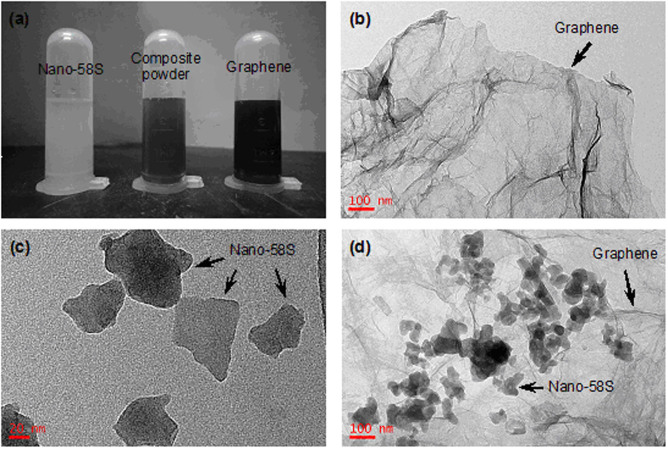
Good dispersibility of graphene in solvent can possess uniform distribution in matrix, which helps to maintain uniform properties throughout the composite. The dispersion states of the starting powders in NMP were shown in Fig. 1a. It can be seen that graphene suspension exhibited visually homogeneous and stable solution with black color. The forces keeping graphene dispersed in NMP arose from the hydrogen bonds formed between graphene and the solvent19. TEM image showed many ripples and wrinkles on the as-received graphene surface (Fig. 1b), which was benefit for protein adsorption and cell adhesion20,21. Besides, nano-58S powder was also well dispersed in the solvent and yielded a white suspension. The powder consisted of irregular particles with a size of 30–60 nm (Fig. 1c). After mixing with graphene suspension and ultrasonication, a composite solution was obtained with dark gray color. And nano-58S particles were found to uniformly and intimately anchor on the graphene surface, as can be seen in Fig. 1d.
Figure 1. Material preparation.
(a) dispersion of the starting powders in NMP. TEM images of (b) as-received graphene, (c) as-received nano-58S powder and (d) graphene/nano-58S composite powder.
Raman analysis was carried out to investigate the structure changes of graphene after the sintering process (Fig. 2). The spectrum of as-received graphene was dominated by a D peak at 1359 cm−1 and a G peak at 1586 cm−1 (Fig. 2a). The G peak referred to C–C stretching vibration while the D peak originated from the structural disorder and defects in graphene22. A broad band was also observed around 2915 cm−1 corresponding to 2D, D + G and 2D′ peaks23. No peaks were found in the spectral region from 1200 to 3200 cm−1 for 58S-0 (Fig. 2b). The aforementioned peaks were presented in the spectra of sintered samples with graphene, confirming the survival of graphene after SLS process. In comparison with the as-received graphene, there was only a slight increase of the intensity ratio of D peak to G peak (ID/IG) for graphene-containing samples (Figs. 2c–f), indicating a higher degree of disorder in the graphene lattice24. The Raman results demonstrated the successful incorporation of graphene into nano-58S scaffold by SLS without obvious structural damage.
Figure 2. Raman spectra.
(a) as-received graphene. (b) 58S-0. (c) 58S-0.1. (d) 58S-0.5. (e) 58S-1. (f) 58S-1.5.
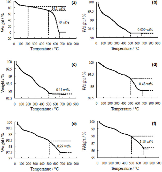
The TGA curves of as-received graphene and sintered samples were obtained (Fig. 3) in order to estimate the weight retention of graphene after the SLS process. The curves showed a weight loss below 200°C, owing to the evaporation of adsorbed water25. A weight loss (14.1 wt%) occurred between 200 and 500°C in the curve of as-received graphene (Fig. 3a), which can be assigned to the oxidation of amorphous carbon26. A significant weight loss (70 wt%) was noticed in the range of 500–675°C, corresponding to the complete combustion of the carbon skeleton of graphene27. In contrast, no obvious weight loss (0.009 wt%) was found in this temperature range for 58S-0 (Fig. 3b). This indicated that the weight loss in the temperature range of 500–675°C corresponded to the graphene content in the sintered samples. As can be seen in Figs. 3c–f, the weight losses in this temperature range were about 0.11, 0.48, 0.99 and 1.53 wt%, which represented the amount of graphene in 58S-0.1, 58S-0.5, 58S-1 and 58S-1.5 respectively. As the temperature increased above 675°C, the weight loss slowed down and plateau formed in the TGA curves. The TGA results demonstrated little weight loss of graphene after the SLS process in nitrogen atmosphere.
Figure 3. TGA curves.
(a) as-received graphene. (b) 58S-0. (c) 58S-0.1. (d) 58S-0.5. (e) 58S-1. (f) 58S-1.5.
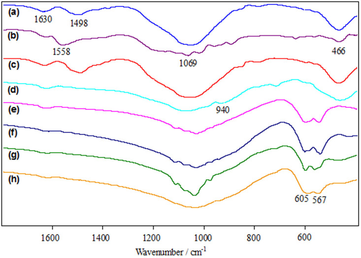
The FT-IR spectra of the starting powders and sintered samples were shown in Fig. 4. The spectrum of as-received nano-58S powder (Fig. 4a) was dominated by a strong absorption band in the region 900–1200 cm−1, which was a combination of Si–O–Si stretching and P–O stretching vibrations in the glass network28. And the absorption peak at 466 cm−1 was ascribed to the bending vibration of Si-O-Si29. The small band appeared in the vicinity of 1498 cm−1 was the typical absorption band of carbonates as a result of the admission of water and CO2 on nano-58S powder30. The spectrum of as-received graphene (Fig. 4b) exhibited an absorption band at 1558 cm−1, associating with the C = C skeletal vibration31. The peak for C = C stretching vibration32 was observed at 1630 cm−1. The dispersive band located around 1069 cm−1 corresponded to the C-O stretching vibration in the reduced graphene33,34. The spectrum of composite powder was similar to that of nano-58S powder due to the low content of graphene (Fig. 4c). Absorption peak at 940 cm−1 was observed in the spectrum of 58S-0 (Fig. 4d), which can be attributed to the formation of SiO groups with non-bridging oxygens35. For the sintered samples with graphene (Figs. 4e–h), a double peak that arose from the bending vibration of P-O appeared at 567 and 605 cm−1, indicating the formation of crystalline phosphate in the glasses36.
Figure 4. FT-IR spectra.
(a) as-received nano-58S powder. (b) as-received graphene. (c) composite powder. (d) 58S-0. (e) 58S-0.1. (f) 58S-0.5. (g) 58S-1. (h) 58S-1.5.
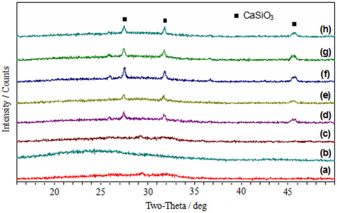
The XRD patterns of the starting powders and sintered samples were shown in Fig. 5. It can be seen that the as-received nano-58S powder was amorphous, and no diffraction peaks were observed except for a broad band of 2θ between 26° and 32° (Fig. 5a). There was only a broad band at about 24° in the pattern of as-received graphene (Fig. 5b), which was attributed to the irregular arrays of atoms in three dimensions37. After mixing with nano-58S powder, no trace of graphene was detected by XRD analysis because of its low amount in the composite powder (Fig. 5c). There was a similar XRD pattern among the sintered samples with and without graphene addition (Figs. 5d–h). Diffraction peaks of wollastonite (CaSiO3) were identified at about 27.5°, 31.7° and 45.7° in all the sintered samples38, indicating partial crystallization occurred in the nano-58S. The addition of graphene had no influence on the phase composition of sintered samples, since no obvious difference were found among the patterns with different graphene contents. Besides, the crystalline phosphate found in the FT-IR results were absent in the XRD patterns, which might be attributed to the trace amount of crystalline phosphate and insufficient detection limit of XRD method39.
Figure 5. XRD patterns.
(a) as-received nano-58S powder. (b) as-received graphene. (c) composite powder. (d) 58S-0. (e) 58S-0.1. (f) 58S-0.5. (g) 58S-1. (h) 58S-1.5.
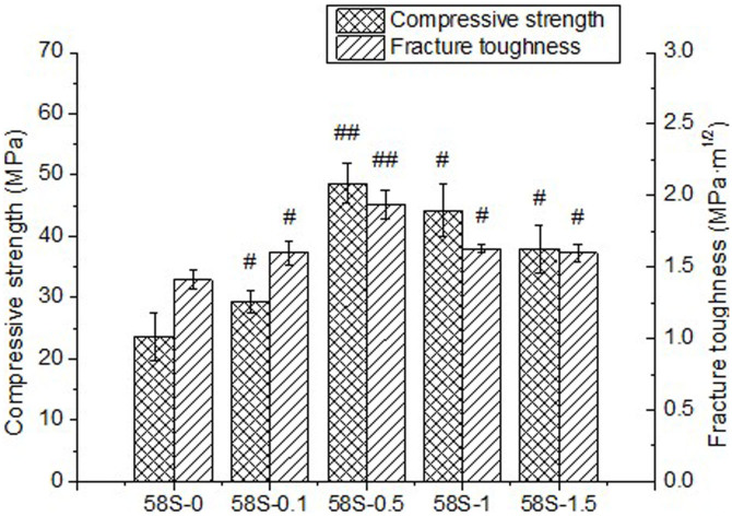
The mechanical properties of sintered samples were obtained by compressive tests and indentation technique, as shown in Fig. 6. It can be seen that the compressive strength firstly increased from 23.66 ± 3.90 MPa for 58S-0 to 48.65 ± 3.19 MPa for 58S-0.5, followed by a decrease to 44.19 ± 4.27 and 37.92 ± 3.84 MPa with increasing graphene content up to 1.0 or 1.5 wt%. The fracture toughness of sintered samples increased with the addition of graphene from 0 to 0.5 wt% and then diminished as graphene content reached 1.0 or 1.5 wt%. Incorporation of 0.5 wt% graphene improved the fracture toughness of nano-58S by 38% from 1.41 ± 0.07 to 1.94 ± 0.10 MPa·m1/2. It was clear from the data that the 58S-0.5 displayed the highest compressive strength and fracture toughness among the samples tested. While the diminished enhancements of 58S-1 and 58S-1.5 might be attributed to the degradation in dispersion of graphene at high content.
Figure 6. Mechanical properties of sintered samples with different graphene contents.
(# p < 0.05, ## p < 0.001 compared with 58S-0).
Apart from the mechanical properties, bioactivity and biocompatibility of 58S-0.5 were studied by SBF and cell culture tests. SEM image revealed that the surface of 58S-0.5 scaffold was covered by a thick and well formed HCA layer after immersion in SBF for 7 days (Fig. 7a). Precipitated granules were found to distribute homogeneously on the surface in the magnified SEM image (Fig. 7b). EDS analysis of the precipitated granules revealed a mean molar Ca/P ratio of about 1.69 (Fig. 7c). XRD analysis (Fig. 7d) indicated that the diffraction peaks of (002) and (211) surfaces of HCA40 were superposed on that of CaSiO3 at 2θ of 25.8° and 31.7°. The other peaks of HCA were observed at 2θ of 39° and 46°, corresponding to the (310) and (222) surfaces respectively41. The apatite layer on 58S-0.5 scaffold was further analyzed using FTIR and shown in Fig. 7e. The double peak corresponding to P–O bending vibrations was observed at 558 and 605 cm−1 in the spectrum, while the P–O stretching band was superposed on the Si–O stretching band of 58S at about 1082 cm−1. Well-defined carbonate bands were presented at 875 (C–O bending vibration) and 1420–1480 cm−1 (C–O stretching vibration)42,43, indicating the incorporation of carbonate into the apatite layer. These findings further confirmed the formation of HCA layer on the surface of 58S-0.5 scaffold after immersing in SBF. In vitro cell culture tests revealed that MG-63 cells colonized and grew favorably on 58S-0.5 scaffold after 7 days (Fig. 7f). MG-63 cells showed a round shape with mineralised nodules and were anchored to the surface by elongated filopodia, suggesting a good cell biocompatibility of the scaffold.
Figure 7. Biological tests.
(a) Low magnification and (b) high magnification SEM images, (c) EDS spectrum, (d) XRD pattern and (e) FT-IR spectrum of 58S-0.5 after immersion in SBF for 7 days. (f) surface morphology of 58S-0.5 after cultured with MG-63 cells for 7 days.
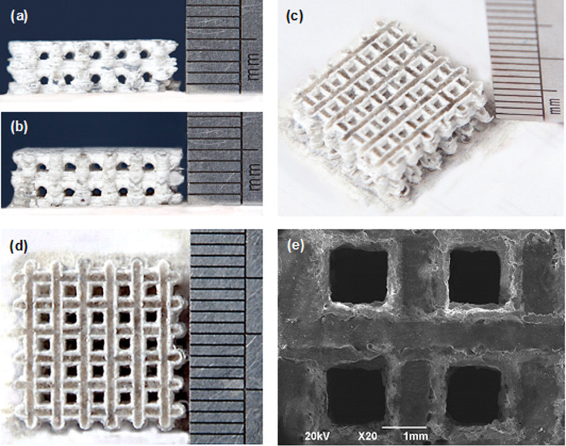
A graphene/nano-58S composite scaffold was fabricated with the optimum graphene content (0.5 wt%) at laser power of 7.5 W, scan speed of 100 mm/min and spot diameter of 1 mm. The digital images of the scaffold (Figs. 8a–d) showed a 3D network of interconnected pores which were approximately 0.8 μm in size and isotropic in their distribution. SEM image indicated good connections between pore walls (Fig. 8e). The high degree of porosity and pore interconnectivity are beneficial for vascularisation in vivo and rapid osteogenesis44.
Figure 8. Graphene/nano-58S composite scaffold by SLS.
(a), (b) side views. (c) isometric view. (d) top view. (e) SEM image.
Discussion
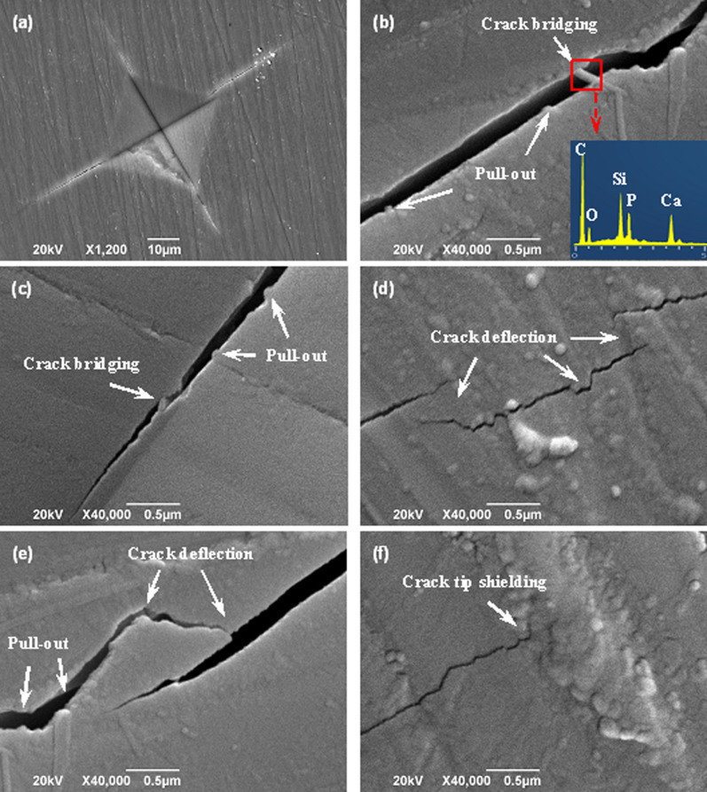
The typical toughening mechanisms for graphene-based materials can be summarized as follows: (a) Crack bridging. Graphene bridges the two surfaces of crack and provides a closure stress to counteract the applied stress, delaying further propagation of the crack. (b) Pull-out. Graphene is pulled out the matrix and slows down crack propagation by the interfacial friction between graphene and matrix. (c) Crack deflection. Crack deflects into a different plane when it encounters graphene, resulting in a tortuous path and more energy dissipation for crack propagation. (d) Crack tip shielding. The crack tip is restricted in the vicinity of graphene due to the insufficient energy required for interface debonding. The indentations and radial cracks were characterized by SEM to identify the mechanism responsible for the enhanced mechanical properties (Fig. 9). A representative microhardness indentation and induced radial cracks were prepared on the polished surface of 58S-0.5 (Fig. 9a). Magnified image in Fig. 9b showed the presence of graphene pull-out and crack bridging (labeled by white arrows) on the fracture line. Individual graphene bridged the gap between the crack surfaces, delaying the rupture of 58S matrix. EDS analysis confirmed the toughening effect by graphene since a strong peak referred to carbon element was observed in the spectrum. The direct evidence of graphene pull-out and crack bridging were also observed in Fig. 9c. The crack propagation was slowed down due to the loss of fracture energy by graphene pull-out. As a result, the reduced fracture energy was insufficient to pull out another graphene sheet and crack bridging formed in the propagation path. Characteristic crack deflections were visible in Fig. 9d and 9e. The crack firstly propagated in its own plane and then along graphene–58S interface when met with graphene, followed by the deflection to 58S matrix. Such crack deflection occurred several times in the propagating path, which would force the crack to propagate along a very tortuous path to release stress. Crack tip shielding by graphene was observed in Fig. 9f, in which graphene effectively prevented the further propagation of crack tip. These results indicated that graphene was highly effective in suppressing crack propagation in 58S matrix. The mechanisms of graphene pull-out, crack bridging, crack deflection and crack tip shielding were responsible for the enhancement of compressive strength and fracture toughness.
Figure 9. Inhibition of crack propagation by graphene in the sintered samples.
SEM images of (a) microhardness indentation and radial cracks, (b–e) Crack deflection, crack bridging and graphene pull-out, (f) Termination of crack growth at the crack tip.
The enhancement mechanisms associated with the morphological evidence were schematically depicted in Fig. 10. Once a matrix crack is initiated and propagates, load is transferred from the matrix to graphene due to the difference in elastic modulus. The wrinkled surface texture of graphene enabled efficient mechanical interlocking and load transfer with the matrix45. The toughening mechanism of crack bridging is shown in Fig. 10a where graphene bridges two crack surfaces. Graphene hampers the relative displacement between the opposite crack surfaces by alleviating the stress required for further crack propagation. The pull-out of graphene occurs when the shear stress at the interface exceeds the interfacial strength of graphene–58S (Fig. 10b). This mechanism requires high energy dissipation due to the high toughness and large surface area of graphene. The crack propagation can be effectively slowed down by additional resistance from the interfacial friction between graphene and 58S matrix. Fig. 10c demonstrates the toughening mechanism of crack deflection. A crack propagates firstly in 58S matrix and then deflects into a different plane when it encounters graphene. More energy is required for the further propagation of crack, since the crack plane is no longer perpendicular to the axis of stress. Moreover, the deflection process generates a tortuous path for crack propagation, which allows much more energy dissipation. Crack deflection may be highly effective for graphene-based materials in virtue of the large specific surface area. As shown in Fig. 10d, the crack tip is restricted in the vicinity of graphene due to the insufficient energy required for interface debonding. These mechanical enhancements get saturated with graphene content of 0.5 wt%, as more graphene are difficult to disperse homogeneously in the nano-58S powder.
Figure 10. A schematic of enhancement mechanisms in the sintered samples.
(a) Crack bridging. (b) Graphene pull-out. (c) Crack deflection. (d) Crack tip shielding. The yellow region refers to 58S matrix, black region refers to graphene, purple region refers to crack, and red arrow refers to the resistance to crack propagation by graphene.
In summary, this study evaluates graphene as a potential reinforcement to nano-58S bone scaffold for enhancing the mechanical properties. Uniform dispersion of graphene, nano-58S and composite powders were obtained using NMP solvent. Graphene was successfully incorporated into the scaffold by SLS without obvious structural damage in spite of a slight increase of ID/IG ratio. And there was little weight loss of graphene in the scaffold after the sintering process. The addition of graphene showed no influence on the phase composition of nano-58S scaffolds. The mechanical properties of nano-58S increased with the increase of graphene content (0–0.5 wt%) and then diminished with graphene content of 1.0 or 1.5 wt%. Incorporation of 0.5 wt% graphene improved the compressive strength of nano-58S by 105% and the fracture toughness by 38%. Microstructural results demonstrated that pull-out, crack bridging, crack deflection and crack tip shielding were responsible for the mechanical enhancement. A well-formed HCA layer with Ca/P ratio of 1.69 formed on the scaffold surface after immersing in SBF for 7 days. In vitro cell culture tests revealed that MG-63 cells colonized and grew favorably on the surface, suggesting a good cell biocompatibility of the composite scaffold. This study may pave the way for the mechanical enhancement of nano-58S scaffold in the application of bone tissue engineering.
Methods
Materials and experiments
Graphene (purity: 99.8%, 0.7–1.2 nm in thickness and 0.8–3 μm in diameter) was purchased from Nanjing JCNANO Tech Co., Ltd. It was prepared by modified Hummers method46 with a metal impurity < 10 PPM. 58S bioactive glass was firstly prepared by sol-gel method. Then freeze-drying and grinding process were adopted to achieve nano-scale 58S powder (average particle size of 48.3 ± 6.6 nm). N-methyl-2-pyrrolidone (NMP) (Tianjin Kemiou Chemical Reagent Co., Ltd., China) was used as the solvent for dispersing graphene due to the well matched surface energy to graphene47.
As-received graphene was firstly weighed using an electronic balance (Model FA1004, Changzhou Hengzheng Electronic Instrument Co., Ltd., China) and dispersed in NMP with concentration of 0.5 mg/ml using ultrasonic cleaning device (SK3300H, Shanghai Kudos Ultrasonic Instrument Co., Ltd., China) for 30 min. Then, a certain amount of nano-58S powder was added to the solution and dispersed ultrasonically for another 30 min. Subsequently, the resultant mixed solution was filtrated and dried by a rotary evaporator (RV 10 digital, IKA, Germany) at 60°C for 24 h, followed by further drying in a vacuum oven (DZ-3, Tianjin Taisite Instrument Co., Ltd., China) for 24 h at 100°C to remove any trapped solvent. Finally, the composite powder was carefully peeled off the filter paper and broken up using pestle. By accurately weighing the graphene and nano-58S powder, the composite powders with different graphene contents (0 wt%, 0.1 wt%, 0.5 wt%, 1.0 wt% and 1.5 wt%) were obtained.
Experiments were carried out on a home-made SLS system in nitrogen atmosphere with laser power of 7.5 W, scan speed of 100 mm/min, spot diameter of 1 mm48,49. And the sintered samples with different graphene contents were labeled as 58S-0, 58S-0.1, 58S-0.5, 58S-1 and 58S-1.5, respectively.
Microstructural characterization
The morphology of graphene, nano-58S and composite powder were observed with a field emission transmission electron microscope (JEM-2100F, JEOL Ltd., Japan) after the powders were ultrasonicated in NMP for 30 min to form homogeneous suspensions. The microstructure of sintered samples were characterized using a scanning electron microscope (JSM-6490LV, JEOL Ltd., Japan) at 20 kV accelerating voltage after the samples were vacuum coated with platinum (JFC-1600 auto fine coater, JEOL Ltd., Japan). The element composition on the sample surface was studied using EDS (Neptune XM4, EDAX Inc., USA).
The phase analysis was conducted on a X-ray diffractometer (D/MAX 2550V, Rigaku, Japan) at 2θ range of 10–60° using CuKα radiation. FTIR spectra were recorded to identify the typical functional groups present in the samples using a Fourier transform infrared spectrometer (Nicolette TM 6700, Thermo Scientific Co., USA). The characterization was conducted with KBr pellets technique in a spectral region of 400–2000 cm−1. In order to determine the structure changes of graphene, Raman spectroscopic studies were performed on a LabRAM HR800 spectrometer (HORIBA Jobin Yvon, France) with laser wavelength of 488 nm and spot size of 0.1 mm. TGA analysis was performed on a thermal analyzer (Netzsch STA 449C, Germany) to determine the weight retention with increasing temperature and further the amount of graphene in the samples. Prior to tests, all the samples were grinded to powders to ensure sufficient heat transfer. The measurements were conducted from ambient temperature to 750°C at a heating rate of 10°C/min under air flow of 30 mL/min.
Mechanical properties assessment
Fracture toughness was determined by the indentation technique using a digital microhardness tester (HXD-1000TM/LCD, Shanghai Taiming Optical Instrument Co., Ltd., China). The samples were firstly inlayed by a mounting press (XQ-2B), followed by surface grinding with abrasive paper and polishing using diamond pastes. The indentations and cracks were made on the samples by loading to the maximum load (500 gf) in 10 s, subsequently holding for 15 s and then unloading to zero load in 10 s. The fracture toughness was calculated based on the crack length according to equation (1)50. A total of ten indentation data points were collected for each sample to check the reproducibility.
 |
Where P is the applied load (N), KIC is the fracture toughness (Pa·m1/2) and c is the diagonal crack length (m).
Compression tests were performed on a universal testing machine (WD-D1, Shanghai Zhuoji instruments Co., Ltd., China) using an S-beam load cell at crosshead speed of 0.5 mm/min. Prior to the tests, samples were ground using abrasive papers (400, 600, 800 and 1000-grit) under water lubrication. Subsequently, the surfaces were polished using successively finer grades of diamond paste to remove grinding damage. Ultrasonic cleaning was then applied to avoid any abrasive entrapment, followed by spraying the surfaces with alcohol and drying under a stream of hot air. The stress–strain curves were recorded and the compressive strengths were calculated from the maximum loads of stress–strain curves. For accuracy of results, ten data points were averaged for each group.
Biological properties assessment
The bioactivity of a scaffold is directly related to its ability to induce HCA formation. The HCA formation behavior of samples was evaluated in vitro by immersing them in SBF. The ion concentration (mmol/L) of SBF51 is similar to that of human plasma and presented as follows: Na+ 142.0, Ca2+ 2.5, K+ 5.0, Mg2+ 1.5, Cl− 147.8, HCO3− 4.2, HPO42− 1.0, and SO42− 0.5. The samples were immersed in SBF (pH = 7.4) with a surface area (cm2) to solution volume (mL) ratio of 0.1 cm2/mL at 37°C for 7 days. The solution was renewed every 3 days to keep the ion concentration and pH constant for better simulation of the in vivo conditions. After immersing, the samples were extracted from the solution, gently rinsed with acetone, and dried at ambient temperature before further characterization.
Cell culture test was conducted to study the biocompatibility of scaffolds using MG-63 cells (American Type Culture Collection, Rockville, MD) isolated from human osteosarcoma. The cells were cultured in Dulbecco's modified Eagle's medium (DMEM, containing 10% fetal bovine serum (FBS), 50 IU/ml penicillin and 50 mg/ml streptomycin) under a humidified atmosphere of 5% CO2 at 37°C. The samples were firstly sterilized with ultraviolet radiation and preconditioned for 24 h in DMEM to prevent the sudden release of high ion concentrations from 58S. Then MG-63 cells were seeded on the samples and incubated in 12-well cell culture plates for 7 days. The medium was changed every 3 days to guarantee a constant nutrition supply. After the cell culture, the samples were rinsed twice in phosphate buffered saline (PBS) and fixed with 2.5% glutaraldehyde. Dehydration was performed by sequential immersion in a graded series of ethanol solutions (70%, 80%, 90%, 95% and 100%). Afterwards, the samples were dried and sputtered with platinum for SEM observations.
Statistical analysis
Data analysis was performed using SPSS 16.0 software (SPSS Inc., Chicago, IL, USA) and the data were expressed as mean ± standard deviation (SD). Statistical analysis was conducted by two-tailed Student's t-tests between groups with different graphene contents (n = 10). Differences were considered statistically significant when p < 0.05.
Author Contributions
C.G. and C.S. conceived and designed the research. C.G., T.L. and S.P. performed experiments. C.G. and C.S. analyzed the data and wrote the manuscript. All authors reviewed the manuscript.
Acknowledgments
This work was supported by the following funds: (1) The Natural Science Foundation of China (51222506, 81372366); (2) Hunan Provincial Natural Science Foundation of China; (3) Program for New Century Excellent Talents in University (NCET-12-0544); (4) The Fundamental Research Funds for the Central Universities(2011JQ005, 2012QNZT015); (5) Project supported by the Fok Ying-Tong Education Foundation, China (131050); (6) Shenzhen Strategic Emerging Industrial Development Funds (JCYJ20130401160614372); (7) The Open-End Fund for the Valuable and Precision Instruments of Central South University; (8) Hunan Provincial Innovation Foundation For Postgraduate.
References
- Labbaf S. et al. Spherical bioactive glass particles and their interaction with human mesenchymal stem cells in vitro. Biomaterials 32, 1010–1018 (2011). [DOI] [PubMed] [Google Scholar]
- Roohani-Esfahani S. I., Nouri-Khorasani S., Lu Z. F., Appleyard R. C. & Zreiqat H. Effects of bioactive glass nanoparticles on the mechanical and biological behavior of composite coated scaffolds. Acta Biomater. 7, 1307–1318 (2011). [DOI] [PubMed] [Google Scholar]
- Oudadesse H., Gloriant T., Fauré J. & Drevet R. Electrophoretic Deposition of Bioactive Glass Coatings on Ti12Mo5Ta Alloy. Key Eng. Mater. 507, 135–140 (2012). [Google Scholar]
- Gerhardt L. C. et al. The pro-angiogenic properties of multi-functional bioactive glass composite scaffolds. Biomaterials 32, 4096–4108 (2011). [DOI] [PubMed] [Google Scholar]
- Hoppe A., Güldal N. S. & Boccaccini A. R. A review of the biological response to ionic dissolution products from bioactive glasses and glass-ceramics. Biomaterials 32, 2757–2774 (2011). [DOI] [PubMed] [Google Scholar]
- Misra S. K. et al. Comparison of nanoscale and microscale bioactive glass on the properties of P(3HB)/Bioglass composites. Biomaterials 29, 1750–1761 (2008). [DOI] [PubMed] [Google Scholar]
- Ma J., Chen C. Z., Wang D. G., Meng X. G. & Shi J. Z. Influence of the sintering temperature on the structural feature and bioactivity of sol–gel derived SiO2–CaO–P2O5 bioglass. Ceram. Int. 36, 1911–1916 (2010). [Google Scholar]
- O'Shea T. M. & Miao X. Preparation and characterisation of plga-coated porous bioactive glass-ceramic scaffolds for subchondral bone tissue engineering. Ceram. Trans. 210, 517–523 (2010). [Google Scholar]
- Boccaccini A. R. et al. Polymer/bioactive glass nanocomposites for biomedical applications: A review. Compos. Sci. Technol. 70, 1764–1776 (2010). [Google Scholar]
- Zhou Y. L., Gao Y. & Chang J. Effects of hydrolysis on dodecyl alcohol-modified bioactive glasses and PDLLA/modified bioactive glass composite films. J. Mater. Sci. 45, 6411–6416 (2010). [Google Scholar]
- Liu A. et al. Novel composites of poly(L-Lactide) and surface modified bioactive SiO2–CaO–P2O5 gel nanoparticles: mechanical and biological properties. Chinese J. Polym. Sci. 27, 415–426 (2009). [Google Scholar]
- Akhavan O., Ghaderi E. & Akhavan A. Size-dependent genotoxicity of graphene nanoplatelets in human stem cells. Biomaterials 33, 8017–8025 (2012). [DOI] [PubMed] [Google Scholar]
- Liang J., Huang Y., Zhang L. & Wang Y. Molecular-level dispersion of graphene into poly (vinyl alcohol) and effective reinforcement of their nanocomposites. Adv. Funct. Mater. 19, 2297–2302 (2009). [Google Scholar]
- Yang K. et al. Graphene in mice: ultrahigh in vivo tumor uptake and efficient photothermal therapy. Nano Lett. 10, 3318–3323 (2010). [DOI] [PubMed] [Google Scholar]
- Sun S., Gao L. & Liu Y. Enhanced dye-sensitized solar cell using graphene-TiO2 photoanode prepared by heterogeneous coagulation. Appl. Phys. Lett. 96, 083113 (2010). [Google Scholar]
- Melchels F. P. W., Domingos M. A. N. & Klein T. J. Additive manufacturing of tissues and organs. Prog. Polym. Sci. 37, 1079–1104 (2012). [Google Scholar]
- Bai P. & Wang W. Selective laser sintering mechanism of polymer-coated molybdenum powder. T. Nonferr. Metal. Soc. 17, 543–547 (2007). [Google Scholar]
- Suárez-González D. et al. Controllable mineral coatings on PCL scaffolds as carriers for growth factor release. Biomaterials 33, 713–721 (2012). [DOI] [PMC free article] [PubMed] [Google Scholar]
- Kim C. J., Khan W., Kim D. H., Cho K. S. & Park S. Y. Graphene oxide/cellulose composite using NMMO monohydrate. Carbohyd. Polym. 86, 903–909 (2011). [Google Scholar]
- Lu J. et al. Self-supporting graphene hydrogel film as an experimental platform to evaluate the potential of graphene for bone regeneration. Adv. Funct. Mater. 23, 3494–3502 (2013). [Google Scholar]
- Nayak T. R. et al. Graphene for controlled and accelerated osteogenic differentiation of human mesenchymal stem cells. ACS nano 5, 4670–4678 (2011). [DOI] [PubMed] [Google Scholar]
- Zhou G. et al. Graphene-wrapped Fe3O4 anode material with improved reversible capacity and cyclic stability for lithium ion batteries. Chem. Mater. 22, 5306–5313 (2010). [Google Scholar]
- Kalita G., Kayastha M. S., Uchida H., Wakita K. & Umeno M. Direct growth of nanographene films by surface wave plasma chemical vapor deposition and their application in photovoltaic devices. RSC Adv. 2, 3225–3230 (2012). [Google Scholar]
- Gollavelli G. & Ling Y. C. Multi-functional graphene as an in vitro and in vivo imaging probe. Biomaterials 33, 2532–2545 (2012). [DOI] [PubMed] [Google Scholar]
- Guo S. et al. Structurally controlled ZnO/TiO2 heterostructures as efficient photocatalysts for hydrogen generation from water without noble metals: the role of microporous amorphous/crystalline composite structure. J. Power Sources 245, 979–985 (2013). [Google Scholar]
- Patole A. S. et al. A facile approach to the fabrication of graphene/polystyrene nanocomposite by in situ microemulsion polymerization. J. Colloid Interf. Sci. 350, 530–537 (2010). [DOI] [PubMed] [Google Scholar]
- Li N. et al. Large scale synthesis of N-doped multi-layered graphene sheets by simple arc-discharge method. Carbon 48, 255–259 (2010). [Google Scholar]
- Aguiar H., Serra J., González P. & León B. Structural study of sol–gel silicate glasses by IR and Raman spectroscopies. J. Non-Cryst. Solids 355, 475–480 (2009). [Google Scholar]
- He Q. et al. Preparation, characterization and application of N-2-Pyridylsuccinamic acid-functionalized halloysite nanotubes for solid-phase extraction of Pb (II). Water Res. 47, 3976–3983 (2013). [DOI] [PubMed] [Google Scholar]
- Groust J. F., Costentin G., Krafft J. M. & Massiani P. Mechanism and deactivation process of the conversion of methylbutynol on basic faujasite monitored by operando DRIFTS. Phys. Chem. Chem. Phys. 12, 937–946 (2010). [DOI] [PubMed] [Google Scholar]
- Zhou K., Zhu Y., Yang X., Jiang X. & Li C. Preparation of graphene–TiO2 composites with enhanced photocatalytic activity. New J. Chem. 35, 353–359 (2011). [Google Scholar]
- Gupta A., Akhtar A. J. & Saha S. K. In-situ growth of P3HT/graphene composites for supercapacitor application. Mater. Chem. Phys. 140, 616–621 (2013). [Google Scholar]
- Choi E. Y. et al. Noncovalent functionalization of graphene with end-functional polymers. J. Mater. Chem. 20, 1907–1912 (2010). [Google Scholar]
- Wang Y., Liu J., Liu L. & Sun D. D. High-quality reduced graphene oxide-nanocrystalline platinum hybrid materials prepared by simultaneous co-reduction of graphene oxide and chloroplatinic acid. Nanoscale Res. Lett. 6, 241–248 (2011). [DOI] [PMC free article] [PubMed] [Google Scholar]
- Mukherjee D. P. & Das S. K. Effects of nano silica on synthesis and properties of glass ceramics in SiO2–Al2O3–CaO–CaF2 glass system: A comparison. J. Non-Cryst. Solids 368, 98–104 (2013). [Google Scholar]
- Hupfer M., Zak D., Roβberg R., Herzog C. & Pöthig R. Evaluation of a well-established sequential phosphorus fractionation technique for use in calcite-rich lake sediments: identification and prevention of artifacts due to apatite formation. Limnol. Oceanogr. Methods 7, 399–410 (2009). [Google Scholar]
- Ma B., Zhou X., Bao H., Li X. & Wang G. Hierarchical composites of sulfonated graphene-supported vertically aligned polyaniline nanorods for high-performance supercapacitors. J. Power Sources 215, 36–42 (2012). [Google Scholar]
- Manda M. et al. The effect of high tempered firing cycle on the bioactive behavior of sol–gel derived dental porcelain modified by bioactive glass. J. Sol-Gel Sci. Techn. 63, 481–494 (2012). [Google Scholar]
- Soong Y., Goodman A. L., McCarthy-Jones J. R. & Baltrus J. P. Experimental and simulation studies on mineral trapping of CO2 with brine. Energy Convers. Manage. 45, 1845–1859 (2004) [Google Scholar]
- Zhang J. et al. Calcium phosphate/chitosan composite coating: Effect of different concentrations of Mg2+ in the m-SBF on its bioactivity. Appl. Surf. Sci. 280, 256–262 (2013). [Google Scholar]
- Lei B., Chen X., Wang Y. & Zhao N. Synthesis and in vitro bioactivity of novel mesoporous hollow bioactive glass microspheres. Mater. Lett. 63, 1719–1721 (2009). [Google Scholar]
- Durdu S., Deniz Ö. F., Kutbay I. & Usta M. Characterization and formation of hydroxyapatite on Ti6Al4V coated by plasma electrolytic oxidation. J. Alloys Compd. 551, 422–429 (2013). [Google Scholar]
- Chen X., Meng Y., Wang Y., Du C. & Yang C. A biomimetic material with a high bio-responsibility for bone reconstruction and tissue engineering. J. Biomat. Sci-Polym. E 22, 153–163 (2011). [DOI] [PubMed] [Google Scholar]
- Vaquette C., Ivanovski S., Hamlet S. M. & Hutmacher D. W. Effect of culture conditions and calcium phosphate coating on ectopic bone formation. Biomaterials 34, 5538–5551 (2013). [DOI] [PubMed] [Google Scholar]
- Rafiee M. A. et al. Fracture and fatigue in graphene nanocomposites. Small 6, 179–183 (2010). [DOI] [PubMed] [Google Scholar]
- Bong S. et al. Graphene supported electrocatalysts for methanol oxidation. Electrochem. Commun. 12, 129–131 (2010). [Google Scholar]
- Pham V. H., Cuong T. V., Hur S. H., Oh E. & Kim E. J. Chemical functionalization of graphene sheets by solvothermal reduction of a graphene oxide suspension in N-methyl-2-pyrrolidone. J. Mater. Chem. 21, 3371–3377 (2011). [Google Scholar]
- Shuai C. et al. Structure and properties of nano-hydroxypatite scaffolds for bone tissue engineering with a selective laser sintering system. Nanotechnology 22, 285703 (2011). [DOI] [PubMed] [Google Scholar]
- Shuai C. et al. Structural design and experimental analysis of a selective laser sintering system with nano-hydroxyapatite powder. J. Biomed. Nanotechnol. 6, 370–374 (2010). [DOI] [PubMed] [Google Scholar]
- Veljovic D., Palcevskis E., Zalite I., Petrovic R. & Janackovic D. Two-step microwave sintering—A promising technique for the processing of nanostructured bioceramics. Mater. Lett. 93, 251–253 (2013). [Google Scholar]
- Leonor I. B. et al. Alkaline treatments to render starch-based biodegradable polymers self-mineralizable. J. Tissue Eng. Regen. M. 1, 425–435 (2007). [DOI] [PubMed] [Google Scholar]


