Abstract
This paper describes a multitasking robotic platform for Minimally Invasive Surgery (MIS). The device is designed to be introduced through a standard trocar port. Once the device is inserted to the desired surgical site, it can be reconfigured by lifting an articulated section, and protruding two tendon driven flexible arms. Each of the arms holds an interchangeable surgical instrument. The articulated section features a 2 Degrees-of-Freedom (DoF) universal joint followed by a single DoF yaw joint. It incorporates an on-board camera and LED light source at the distal end, leaving a Ø3mm channel for an additional instrument. The main shaft of the robot is largely hollow, leaving ample space for the insertion of two tendon driven flexible arms integrated with surgical instruments. The ex-vivo and in-vivo experiments demonstrate the potential clinical value of the device for performing surgical tasks through single incision or natural orifice transluminal procedures.
I. Introduction
The advantages of Minimally Invasive Surgery (MIS) are now well recognized, bringing reduced surgical trauma, shortened hospital stays, and improved patient recovery [1]. With increasing clinical uptake of MIS for many of the routine surgical procedures, the surgical community is also attempting to further expand the boundary of MIS by developing Natural Orifice Transluminal Endoscopic Surgery (NOTES) [2].
The primary advantage of NOTES is often attributed to the avoidance of external scar. However its real-promise is in its flexible access, making it particularly suited for some of the gastrointestinal and gynaecological procedures. Thus far, most attempts of NOTES procedures are performed with either standard or modified endoscopes [4-6]. These devices, however, carry many ergonomic concerns largely because flexible endoscopes are not suitable for intra-abdominal tasks where appropriate counter-traction and accuracy are required. Secondly, disorientation and operation difficulties are major hurdles to overcome applications because of the small field-of-view of the endoscope and device manipulation challenges due to a lack of consistent and repeatable control of the device [7,8].
These problems are not encountered in traditional laparoscopic surgery because of the rigid laparoscopic instruments used. By carefully placing the incision points, good visualization and access to some certain surgical site can be achieved. However, it has restricted access to anatomical targets, requiring well-planned, multiple incision points. Furthermore, the fulcrum effect coupled with a lack of force control makes the procedure challenging to perform, which is often associated with a long learning curve.
In line with the traditional laparoscopic surgery, Single Port Laparoscopic Surgery (SILS) is a branch of the laparoscopic surgery, which uses only one incision. A multi-functional port is usually placed at the incision point and all the visualization and surgical instruments go through the same port. The advantages of SILS compared to the traditional multi-port laparoscopic surgery include less invasion, better cosmetic results and less postoperative pain [9,10]. The disadvantages of SILS include operation difficulties due to the way to provide adequate triangulation for the instruments, entailing large external workspace and confliction between operators.
The evolution from the traditional MIS to SILS and NOTES has placed a significant demand on the development of multitasking, bimanual platforms that can be inserted through single incision or natural orifices. Thus far, there are several multitasking platforms developed, including the Direct Drive system developed by Boston Scientific Corp [11], the Transport and Cobra by USGI [12], and the R-Scope and EndoSAMURAI by Olympus Medical Corp. These platforms are designed with NOTES SILS in mind and have attracted extensive clinical interest. A number of studies comparing the multitasking platforms with traditional dual-channel endoscopes have been performed [13-15]. It has been found that these platforms advantageous in terms of more stable control, however, limited triangulation and accuracy still represent major operation difficulties.
Surgical robotic systems, such as the da Vinci Surgical System by Intuitive Surgical, on the other hand benefit from improved precision and ergonomics, better visualization, and the availability of remote surgery. Despite its high cost, the clinical uptake of these surgical platforms is continuously expanding. In this regard, the development of a multitasking, bimanual platform with robotically controlled actuations has clear advantages.
Thus far, a number of research platforms for flexible access surgery have been developed. These include the continuum robotic arms by Columbia University [16], a bimanual master-slave manipulator that can be attached to a standard endoscope [17], the ARAKNES platform by an EU consortium [18] and the i-Snake® by Imperial College London [19]. Other platforms include Viacath [20], which consists of a flexible overtube that runs alongside a standard gastroscope or colonoscope with two distal articulated robotic instruments that are tendon driven based on serially linked joints. All these are driving towards the development of a flexible multitasking robot that can perform a complete surgical procedure through a single incision, easy to operate and taking up minimal theatre footprint.
The purpose of this paper is to present the design and construction of a flexible robotic platform with bimanual instruments that can be introduced through a single incision port, reconfigurable at the surgical site, and easy to operate. The remaining of the paper is organized as follows. Section II describes the overall design of the platform in terms of mechatronic design. Workspace measurement and the in-vivo experiment on a live porcine model are presented in Section III. Conclusion and discussion of future work are given in Section IV.
II. Mechatronic Design
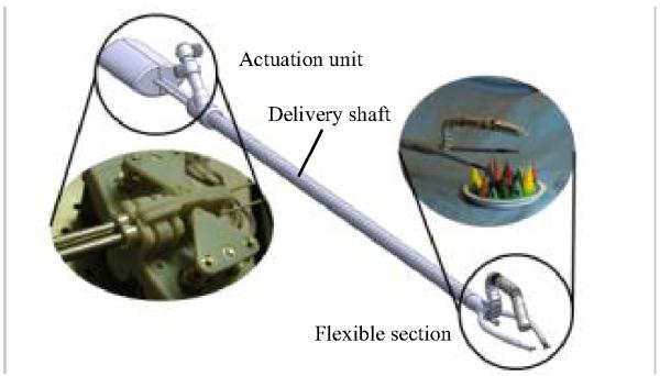
The proposed device consists of three sections as shown in Fig. 1. It includes an actuation pack located at the proximal end; a delivery shaft that delivers the action to the surgical site; and a flexible instrument section located at the distal end of the device.
Fig.1.
System configuration showing the flexible section, delivery shaft and the actuation pack.
The flexible section for surgical instruments comprises three components. The first component is an articulated section driven by a hybrid micro-motor design similar to [19]. This is dubbed as the “head” of the device. The embedded motor driving design eliminates complexity of running tendons through the delivery shaft to the proximal end where actuation pack is located, which usually leads to large theatre footprint. It also features an instrument channel to provide the possibility of introducing an additional instrument. The “head” is mounted to the “neck” of the device, which is made of a series of links driven by tendons, manually actuated by mechanism located at the actuation unit of the device. The third component of the instrument section includes the flexible surgical arms incorporating the surgical instruments. They are also driven by tendons attached to the distal end and actuated by DC motors in the actuation pack. Each of these components will be introduced in more details later.
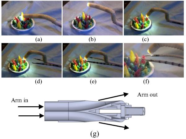
Prior to the insertion of the device, the arms are fully retracted into and concealed inside the delivery shaft, while the neck and head are positioned straight, as shown in Fig. 2(a). The profile of the device is constrained within the volume of a cylinder with diameter of 16mm. Once the device is inserted through an incision port, the flexible section is reconfigured by raising the head and advancing the two arms. The reconfigured device is shown in Fig. 2(b )-(f). The head is raised by actuating the neck to form an “s” bend. The arms are then extended from the two sides of a bespoke plug located between the instrument section and the main shaft. The plug, as in Fig. 2(g), features two curved channels bifurcating from each other, resulting in the two arms diverge from one another to provide the necessary triangulation required during SILS or NOTES.
Fig.2.
Configuration of the robot at different stages of insertion to the surgical site. (a) Configuration before insertion. The neck is straight and arms are retracted. (b), (C) The head is lifted and activated. (d), (e) Arms advanced. (f) The arms and head activated. (g) Cross section view of the plug that diverge the two arms to provide triangulation.
For the proposed platform, each of the arms is made of superelastic Nitinol tube with slots on the wall to enable two-directional flexibility. Four tendons attached to the distal end of the arm at 90° separation run along the arm towards the proximal end. At the proximal end, the tendons are wound on two capstans driven by two DC motors. Each motor actuates a pair of tendons at the opposite positions.
Each of the arms accommodates an interchangeable instrument that has two DoF movement for performing translation and rotation, as well as a single DoF end effector actuation, e.g. gripper open/close. In this prototype, the instrument translation, rotation and actuation are manually controlled by the operator.
In addition to the two instruments manipulated by the arms, there is a 3mm channel within the articulated section that provides the possibility of passing a third instrument through.
Two cameras are used for visualization. One (Medigus 1.8mm) mounted at the tip of the head for regional view and the other one (Medigus 3.0mm) mounted at the proximal end of the neck for broader view of the surgical site. Two illumination LED lights are mounted at the tip.
A. Design of the Articulated Section
The articulated section comprises the head and neck. The head features a 2-DoF universal joint followed by a single DoF yaw joint. Each DoF is driven by an embedded micro motor using a hybrid gear-tendon mechanism as described in [19]. Each DoF of the articulated section can be actuated by ±45°. In order to provide a better coverage of the surgical site and the dexterous workspace of the two instruments, the neutral position of the universal joint is arranged to angle downwards by 30°. As a result, the travel range of the universal joint is + 15° to −75° in the vertical plane and ±45° in the horizontal plane. As the yaw joint that also travels at ±45°, the travel range of the head is ±90° horizontally and + 15° to −75° vertically.
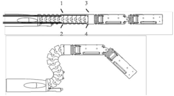
The neck is formed of a series of links with all pivoting axes perpendicular to the plane of the bending, as shown in Fig. 3. The neck is controlled by two pairs of tendon, with one pair terminates at the distal end of the links and the other pair terminates at the middle link. By actuating the two pairs of tendon, an “s” bend can be formed to lift the head up to the deployed position. The tendons are manually driven by two knobs located at the proximal end of the device. There are mechanical hard limits for straight position and maximum bending position, as shown in Fig. 3. These hard limits make the control of the section very easy to reach the two mostly desired positions, straight and “s” bend.
Fig. 3.
The neck in straight position (top) and in deployed position(bottom). Also showing the tendon termination points.
B. Instrument Manipulation
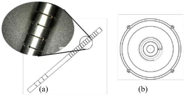
The two interchangeable instruments are manipulated by two arms made of super-elastic Nitinol overtubes. Diameter of each overtube is 5mm and length is 150mm. The overtubes are designed to comprise two sections as shown in Fig. 4. The distal section features slots in two orthogonal planes. This results in actuation being possible in any direction by combining the actuating force in the two planes appropriately. The second section features slots in one plane to passively follow the curved path of the plug. Each arm is delivered by a stainless steel tube that runs all the way along the main shaft of the device.
Fig. 4.
(a) Design of one arm, with two plane cutting at the distal section and one plane cutting at the proximal section; (b) Cross section view showing four tendons attached and flexible shaft at the centre.
Four tendons run along the outside of the overtube at 90° separation. The tendons are welded at the distal end of the tube, run along the entire length to the actuation-pack located at the proximal end and driven in pairs by two DC motors. Each tendon is paired with the opposite one, so that when the driving motor rotates, one tendon pulls back and the opposite tendon pays out, results in the tube bending towards the pulling tendon. The distal section with slots in two planes means there is no back-bone to support the structure. Therefore, the tendon driving fashion inevitably causes compression along the axis. This problem is addressed by carefully designing of the slots to have thick wall transversely to withstand more axial force and thin wall along the axis to enable easy bending.
The overtubes are designed to have maximum bending of ±90°. The length difference between the compressed edge and the central line is
| (1) |
where r is the radius of the tube. The maximum Δl is the amount of compression when all the slots are completely compressed. Therefore, each slot width can be Δl/n, where n is the number of slots in one plane. By minimizing the slot width, the maximum capability of withstanding the axial force is achieved while fulfills the actuation range requirement.
C. Instrument Design
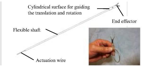
The design specification of the instruments demands the device to have (1) end effector actuation; (2) rotation and translation within the overtube; (3) flexibility to be manipulated by the overtube. The challenge of the design lies in the combination of flexibility and force/torque transmission over a long distance. Each instrument is required to have 1 m in length to allow it to be delivered from the proximal end, through the delivery shaft, to the front of the arms. The detailed design of a surgical gripper, as an example, is shown in Fig. 5.
Fig. 5.
Configuration of a surgical gripper designed for the device with a picture of a complete instrument.
The actuation of the end effector is achieved by using a single wire through a channel to push and pull the mechanism. Rigid rods cannot be used in this case due to lack of flexibility, while flexible wires are not suitable for push action over long distance. A suitable wire must combine flexibility that can be easily bent and rigidity that can be pushed to open the end effector. We chose Ø0.8mm, 1×7 strand stainless steel wire which well fulfills the requirement.
The cylindrical surface of the end effector is 20mm long. It sits at the front end of the arm where the internal surface the arm provides support for the translation and rotation. The translation is limited to 15mm so that only part of the cylindrical surface can protrude from the arm channel.
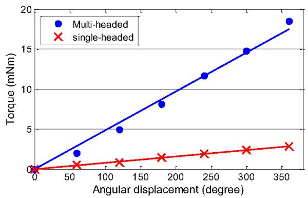
The channel that accommodates the actuation wire and delivers the end effector not only needs to be flexible to be actuated by the overtube, but also needs to withstand compression force while the actuation wire is pulled. Furthermore, it is the key component to deliver torque to the end effector. Typical endoscopic instruments use single-headed coil that is tightly wound. Although it is flexible and can withstand compression force, it is not suitable if torque transmission is required. Multi-headed helical hollow strand combining flexibility and torque transmission capability fulfills the requirement. The torque transmission capability of the two materials is shown in Fig. 6. One material is a single-headed coil with outer diameter (OD) of 2.2mm, 1m in length, 0.5mm wire diameter. The second material is a multi-headed helical hollow strand (6 wires) with the same OD, wire size and length (one meter). The torque was measured by attaching one end of the coil to a force-torque sensor (ATI Nano17) that is clamped to a table and the other end to a dial. By rotating the dial, the torque is transmitted to the sensor. Torque exerted by up to 360° rotational displacement was measured. The result shows that the multi-headed coil transmits about six times more torque compared with the single-headed coil at the same angular displacement.
Fig. 6.
Comparison of torque transmission capability. The red line indicates the single-headed coil, the blue line indicates the multi-headed helical strand.
A. Drive and Control Interface
The articulated joints section is driven in the same way as described in [19] using a thumb-stick and toggling between the joints by an embedded push button. Two Phantom Omni haptic devices (Sensable, Wilmington MA) are used to control the two arms. The 2D motion of the handles is mapped with the overtube bending direction respect to the handle movement. A damping factor was given to let the operator feel the movement.
III. System performance experiments
A. Work Space Measurement
The workspace of the two instruments and the head was measured by using the Aurora Electromagnetic Measuring System (NDI, Canada). The field generator was placed in front of the device, and the sensors were placed at the tip of each instrument or articulated joints.
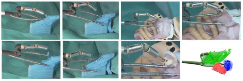
Both the instruments and the head were moved thoroughly so that the whole moving range of each sensor was captured. Fig. 7 shows the head and instruments work space coverage in respect to the performed tasks. The last figure shows the measured workspace coverage. The blue and red areas indicate the workspace of the left and right instrument respectively, while the green area indicates the workspace of the head.
Fig. 7.
Capability of performing surgical steps, dissection using one gripper and a pair of scissors (left), suturing using two needle holders (second column), targeted ablation using two instruments to manipulate tissue and the third instrument delivered through the working channel in the articulated section (right). The last figure shows the plotted workspace of the head and instruments using data acquired with Aurora Electromagnetic Measuring System.
The cross section of the workspace for each instrument is close to a rectangle shape rather than an ideal circle. This is due to the slots are cut in two planes instead of being distributed circularly. The manufacturing error of the position of the four tendons is the main reason of the rectangular shape instead of a square.
Each of the instrument covers around 40mm-60mm area with a small overlap that is clearly shown in the figure. The overlapping area is very important for bimanual manipulation during tasks such as passing a needle from one needle holder to the other. Although the arms are designed to have 90° bending, it was not achieved due to the stiffness of the sheath, which is also the reason of the small overlapping area.
The workspace of the head sits on top of the two instruments workspace and covers both the areas. This is to ensure that the entire range of the surgical site can be visualized. When it is required, the third instrument can be delivered through the instrument channel of the head to anywhere that the two arm instruments can reach.
B. In-vivo Porcine Surgical Experiment
The clinical application of the robot was evaluated in a live porcine model under ethical approval (80/2297). For the purpose of the study, a trans-umbilical access was undertaken to target the pelvic cavity whilst a natural orifice trans-vaginal approach was developed to target the upper abdominal organs.
For the transvaginal approach, an incision was made in the posterior fornix of the cervix, anatomically a point which communicates directly with the peritoneal cavity. An extended 15mm diameter trocar port was inserted through the incision which provided a stable access channel to the abdominal cavity for the robot. The robot was inserted until clearance of the side arms was assured internally, before it was reconfigured by lifting the head up and advancing the two arms out. In this configuration surgical tasks could be undertaken.
The two instrument arms were directed to locate and manipulate target tissue which in this case was small bowel. Visualization was provided by the two cameras, one located at the base of the neck providing a forward view of the instrument arms, and the other at the tip of the end articulating section providing a bird’s eye view over the instrument tips. Large organ manipulation was found to be challenging due to the force requirements on the flexible arms. Fig. 8 shows the robot performing small bowl inspection.
Fig. 8.
One surgeon operating the instruments and another surgeon operating the arms. The robot was deployed trans-vaginally, performing small bowl inspection.
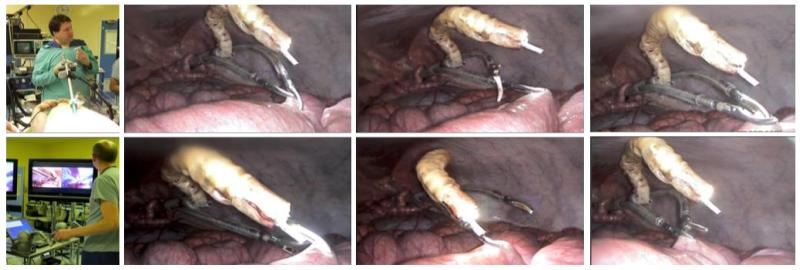
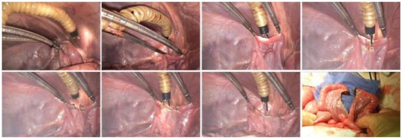
To assess the potential clinical value of the platform, a tubal ligation procedure, an operation performed for sterilization in women, was undertaken using the transabdominal approach. A single 15mm trocar port was placed trans-cutaneously in the upper abdomen of the pig with the uterine horn in the pig targeted due to its close resemblance to the human fallopian tube in position and dimensions. The trocar port was angled acutely towards the pelvis to enable the robot to be inserted fully without interference from the other abdominal organs before full configuration to the effective surgical device could be performed as described above. The robot was manually positioned to target each of the uterine horns in tum. The two arms were used to hold the uterine horn providing lateral traction and counter-traction essential for safe exposure and dissection. A 2.3mm flexible needle-knife cautery instrument was passed through the working channel in the articulating head and its external position was controlled through the actuation of the head. With the tension placed on the tissue by the instrument arms the needle-knife was able to dissect through the horns with relative ease. Fig.9 shows different stages of the two arms holding the uterine horn and diathermy delivered.
Fig. 9.
Different stages of the two arms holding a uterine horn to provide traction and counter-traction force, diathermy probe through the third instrument channel to cut the tissue.
IV. Discussion and future work
In this paper, we have presented the design and experiments of a flexible, multitasking robotic platform for single port or NOTES surgery. The advantages of the device include: flexible arms and instruments for tissue manipulation, interchangeable instruments, actuated visualization and third instrument delivery channel, improved ergonomics. The in-vivo experiments demonstrate the usability of inspection, tissue destruction/resection using the platform.
For the prototype presented in this paper, a rigid delivery portion was fabricated. This has limited the access capability of the device. An actuated flexible delivery portion will enhance the device’s access capability, and avoid manual manipulation of the device pivoting against the incision point. The dexterity of the flexible arms and instruments of the current can also be further extended. Adding an additional wrist function to each of the instrument can significantly improve the performance. For a device has so many DoFs, issues related to human-robot control needs to be addressed. Currently, a damping factor is applied to the Phantom Omni for the operator to “feel” the arms are being driven Integration of force sensing to provide haptic feedback is highly desirable.
Acknowledgment
This work was supported by the i-Snake® programme of the Wellcome Trust [GR083689].
The authors are grateful for the help of the staff at the Department of Surgical Research, Northwick Park Institute for Medical Research.
References
- [1].Fuchs KH. Minimally Invasive Surgery. Endoscopy. 2002;34:154–159. doi: 10.1055/s-2002-19857. [DOI] [PubMed] [Google Scholar]
- [2].Halim I, Tavakkolizadeh A. NOTES: The next surgical revolution? International Journal of Surgery. 2008 Aug;6(4):273–6. doi: 10.1016/j.ijsu.2007.10.002. [DOI] [PubMed] [Google Scholar]
- [3].Kahnamoui K, Cadeddu M, Farrokhyar F, Anvari M. Laparoscopic surgery for colon cancer: a systematic review. Canadian Journal of Surgery. Journal Canadien de Chirurgie. 2007;50(1):48–57. [PMC free article] [PubMed] [Google Scholar]
- [4].Marecaux J, Dallemagne B, Perretta S, Wattiez A, Mutter D, Coumaros D. Surgery Without Scars: Report of Transluminal Cholecystectomy in a Human Being. Arch Surg. 2007;142:823–826. doi: 10.1001/archsurg.142.9.823. [DOI] [PubMed] [Google Scholar]
- [5].Fong DG, Pai RD, Thompson CC. Transcolonic endoscopic abdominal exploration: a NOTES survival study in a porcine model. Gastrointestinal Endoscopy. 2007 Feb;65(issue 2):312–318. doi: 10.1016/j.gie.2006.08.005. [DOI] [PubMed] [Google Scholar]
- [6].Wolfe B, Gardiner B, Leary B. Endoscopic cholecystectomy: Analysis of complications. Arch. Surg. 1991;126:1192–1196. doi: 10.1001/archsurg.1991.01410340030005. [DOI] [PubMed] [Google Scholar]
- [7].Swanstrom L, Zheng B. Spatial orientation and off-axis challenges for NOTES. Gastrointest Endosc Clin N Am. 2008;18:315–324. doi: 10.1016/j.giec.2008.01.015. [DOI] [PubMed] [Google Scholar]
- [8].Clark J, Sodergren M, Noonan DP, Darzi A, Yang G-Z. The Natural Orifice Simulated Surgical Environment (NOSsE): Exploring the Challenges of NOTES Without the Animal Model. J Laparoendosc Adv Surg Tech A. 2009;19:211–214. doi: 10.1089/lap.2008.0357. [DOI] [PubMed] [Google Scholar]
- [9].Chow A, Purkayastha S, Aziz O, Paraskeva P. Single-incision laparoscopic surgery for cholecystectomy: an evolving technique. Surgical Endoscopy. 2009 doi: 10.1007/s00464-009-0655-4. [DOI] [PubMed] [Google Scholar]
- [10].Raman JD, Cadeddu JA, Rao P, Rane A. Single-incision laparoscopic surgery: initial urological experience and comparison with natural-orifice transluminal endoscopic surgery. BJU International. 2008;101:1493–1496. doi: 10.1111/j.1464-410X.2008.07586.x. [DOI] [PubMed] [Google Scholar]
- [11].Thompson CC, Ryou M, Soper NJ, Hungess ES, Rothstein RI, Swanstrom LL. Evaluation of a manually driven, multitasking platform for complex endoluminal and natural orifice transluminal endoscopic surgery applications (with video) GASTROINTESTINAL ENDOSCOPY. 2009;70(1) doi: 10.1016/j.gie.2008.11.007. [DOI] [PubMed] [Google Scholar]
- [12].Bardaro SJ, Swanstro L. Development of advanced endoscopes for Natural Orifice Transluminal Endoscopic Surgery (NOTES) Minim Invasive Ther Allied Technol. 2006;15(6):378–383. doi: 10.1080/13645700601038069. [DOI] [PubMed] [Google Scholar]
- [13].Ikeda K, Sumiyama K, Tajiri H, Yasuda K, Kitano S. Evaluation of a new multitasking platform for endoscopic full-thickness resection. Gastrointestinal Endoscopy. 2011 Jan;73(Issue 1):117–122. doi: 10.1016/j.gie.2010.09.016. [DOI] [PubMed] [Google Scholar]
- [14].A multitasking platform for natural orifice translumenal endoscopic surgery (NOTES): a benchtop comparison of a new device for flexible endoscopic surgery and a standard dual-channel endoscope. SURGICAL ENDOSCOPY. 23(12):2720–2727. doi: 10.1007/s00464-009-0476-5. DOI: 10.1007/s00464-009-0476-5. [DOI] [PubMed] [Google Scholar]
- [15].Shaikh SN, Thompson CC. Natural orifice translumenal surgery: Flexible platform review. World J Gastrointest Surg. 2010 Jun 27;2(6):210–216. doi: 10.4240/wjgs.v2.i6.210. [DOI] [PMC free article] [PubMed] [Google Scholar]
- [16].Simaan N, Xu K, Wei W, Kapoor A, Kazanzides P, Taylor R, Flint P. Design and Integration of a Telerobotic System for Minimally Invasive Surgery of the Throat. International Journal of Robotics Research. 2009 doi: 10.1177/0278364908104278. [DOI] [PMC free article] [PubMed] [Google Scholar]
- [17].Phee SJ, Low SC, Sun ZL, Ho KY, Huang WM, Thant ZM. Robotic System for No-Scar Gastrointestinal Surgery. Int J Med Robot. 2008;4:15–22. doi: 10.1002/rcs.179. [DOI] [PubMed] [Google Scholar]
- [18].Piccigallo M, Scarfogliero U, Quaglia C, Petroni G, Valdastri P, Menciassi A, Dario P. Design of a Novel Bimanual Robotic System for Single-Port Laparoscopy. IEEE/ASME Transactions on Mechatronics. 2010 Dec;15(6) [Google Scholar]
- [19].Shang J, Noonan D, Payne C, Clark J, Sodergren MH, Darzi A, Yang G-Z. An Articulated Universal Joint Based Flexible Access Robot for Minimally Invasive Surgery; IEEE International Conference on Robotics and Automation (ICRA); 2011. [Google Scholar]
- [20].Abbott DJ, Becke C, Rothstein R, Peine WJ. Design of an Endoluminal NOTES Robotic System. IEEE International Conference on Intelligent Robots and Systems. 2007:410–416. [Google Scholar]


