Abstract
The recent introduction of surface acoustic wave (SAW) technology onto lab-on-a-chip platforms has opened a new frontier in microfluidics. The advantages provided by such SAW microfluidics are numerous: simple fabrication, high biocompatibility, fast fluid actuation, versatility, compact and inexpensive devices and accessories, contact-free particle manipulation, and compatibility with other microfluidic components. We believe that these advantages enable SAW microfluidics to play a significant role in a variety of applications in biology, chemistry, engineering, and medicine. In this review article, we discuss the theory underpinning SAWs and their interactions with particles and the contacting fluids in which they are suspended. We then review the SAW-enabled microfluidic devices demonstrated to date, starting with devices that accomplish fluid mixing and transport through the use of travelling SAW; we follow that by reviewing the more recent innovations achieved with standing SAW that enable such actions as particle/cell focusing, sorting, and patterning. Finally, we look forward and appraise where the discipline of SAW microfluidics could go next.
1. Introduction
During the past two decades, microfluidics has emerged as an important platform in chemistry, biology, and medicine.1–9 The introduction of “lab-on-a-chip” (i.e., small-sized analytical devices) has spurred steadily increasing interest and research efforts in the microfluidics discipline (upon which lab-on-a-chip devices are based). The promise of such lab-on-a-chip devices is grounded in the advantages of microfluidics relative to traditional laboratory techniques used in chemistry and biomedicine: system miniaturization, automation, low cost, reduced reagent and sample consumption, rapid turnaround time, and precise microenvironment control. With an aim to improve the functionality, versatility, and performance of lab-on-a-chip devices researchers have continued to integrate new physics into the microfluidic platform. For example, the incorporation of electrowetting in microfluidics has enabled effective on-chip manipulation of droplets, i.e., digital microfluidics.10,11 Incorporation of magnetics in microfluidics has led to the demonstration of highly efficient cell manipulation and separation12–14 and incorporating optics in microfluidics has spurred the development of fluid-based optical components such as optofluidic lasers, lenses, and modulators with unprecedented tunability.15–19
In recent years, surface acoustic wave (SAW) technologies have begun to receive significant attention in the microfluidics community. SAWs are acoustic waves that propagate along the surface of an elastic material. To date, SAW technologies have been used extensively in the telecommunication industry (e.g., cell phones) for signal processing and filtering.20 Other established applications of SAW technologies include touchsensitive screens and biological/chemical sensing.21–25 Recent research demonstrates that SAWs provide an effective means to control fluids and particles in lab-on-a-chip devices.26 These SAW-based microfluidic devices offer the following useful and inimitable combination of features:
Simple, compact, inexpensive devices and accessories: SAW devices have been used extensively in various compact commercial electronic systems, such as cell phones (each cell phone manufactured today contains multiple SAW devices which, along with their accessories, occupy only a small portion of the phone volume). This widespread commercial deployment demonstrates that SAW devices—and the accessories needed to drive them (such as driving circuits and power supplies)—are compact, inexpensive, and highly reliable.20 SAW-based microfluidic devices would be simple and inexpensive to fabricate and integrate with other on-chip components in mass production.
High biocompatibility: The acoustic power intensity and frequency used in many SAW-based microfluidic devices are both in a range similar to those used in ultrasonic imaging, which has been used extensively for health monitoring during various stages of pregnancy and proven to be extremely safe.27 Therefore, we expect that with proper design, SAW-based microfluidic devices will also be safe and biocompatible with cells, molecules, and other biological samples. This expectation has been partially confirmed by cell viability and proliferation tests using existing acoustofluidic devices.28–30
Fast fluidic actuation and large forces: Current microfluidic technologies have difficulty generating fast fluidic actuation or large forces on particles. These drawbacks have limited their applications in medical diagnostics and biochemical studies. As indicated in a review article on microfluidics,5 “small feature sizes typically prevent flow velocities from being high enough to yield high (Reynolds) numbers. High-frequency acoustic waves, however, can circumvent such difficulties.” SAW-based devices can be used to selectively introduce chaotic advection31 to a microfluidic system (in which laminar flow generally dominates), thereby enabling fast, effective manipulation of fluids and particles. Thus far, SAW-based microfluidic devices have proven to be able to pump fluids at 1–10 cm/s31 and manipulate mm-scale objects (e.g., C. elegans).29Neither of these two features can be readily achieved by other microfluidic techniques.
Versatility: SAW technologies enable biological/chemical detection, fluidic control (e.g., fluid mixing, translation, jetting, and atomization), and particle manipulation (e.g., focusing, patterning, separation, sorting, concentration, and re-orientation). SAW technologies are capable of manipulating most microparticles, regardless of their shape, electrical, magnetic, or optical properties; they are capable of manipulating objects with a variety of length scales, from nm to mm; and they are capable of manipulating a single particle or groups of particles (e.g., tens of thousands of particles).
Contact-free manipulation: SAWs manipulate particles and cells by means of the primary acoustic radiation force applied by the surrounding fluid; and SAWs manipulate fluid by means of acoustic waves leaked into the fluid. This represents contact-free manipulation, eliminating the potential for sample contamination.
Convenient on-chip integration with SAW-based sensors: SAW microfluidic devices can perform not only precise manipulation and control of both fluids and particles, but can also perform sensitive detection and sensing. SAW-based microsensors have matured over the years and can be integrated with other SAW-based microfluidic components.21–23 These characteristics make it feasible to realize SAW-based, fully integrated, true lab-on-a-chip systems that can be launched into practical settings, rather than the chip-in-a-lab systems that we often encounter in the microfluidics community.
When compared with bulk acoustic wave (BAW) microfluidics,33 another subset of acoustofluidics (i.e., the fusion of acoustics and microfluidics), SAW microfluidics has its advantages and limitations. While BAW microfluidics is more mature, better understood, and has demonstrated higher throughput, SAW microfluidics has the following advantages:
It allows one to better control excitation frequencies in a wider range and utilize higher excitation frequencies whenever needed. As a result, SAW microfluidics is more versatile and flexible and can achieve more precise and controllable manipulation of fluids and particles.
It does not require that fluid channels be made of materials with high acoustic reflection, making it possible to employ microfluidic devices made of polymers, which generally have low acoustic reflection.
Because SAWs confine most of their energy to the surface of a microfluidic device substrate (whereas BAWs expend energy traveling through the bulk of the device substrate), they require less power than BAWs to achieve the same acoustic effects.
SAW devices can be conveniently fabricated on the same chip as many other microfluidic components through standard micro/nano fabrication processes in a massproducible fashion. In this regard, SAW microfluidics appear to be more amenable to system integration and mass production than BAW microfluidics.
These recognized features and advantages of SAW microfluidics (relative to BAW microfluidics and other microfluidic approaches) have rendered it an attractive platform for many lab-on-a-chip applications. Although some aspects of SAW microfluidics have been reviewed elsewhere34–39 (such as traveling SAW based droplet microfluidics, SAW based particle manipulation, and SAW based biosensing in microfluidics), we provide in this article a comprehensive review of SAW microfluidics. We propose the decomposition of SAW microfluidics into two types: travelling SAW (TSAW) and standing SAW (SSAW). For both SAW types, we first introduce the theory before summarizing microfluidic applications to date. Finally, we look forward to identify areas with space for research innovations.
2. Travelling Surface Acoustic Wave (TSAW) Microfluidics
2.1 Theory Involved with TSAW
2.1.1 Generation of SAWs
The best-known form of SAW, Raleigh SAW, is composed of a longitudinal and a vertically polarized shear component.38 Rayleigh SAW strongly couples with media in contact with the wave propagation surface, enabling the sensing of mass perturbation and elastic properties of a medium introduced on the wave’s propagation path. Other SAW modes exist in elastic materials of different compositions. For example, Love SAW is a guided shear-horizontal wave that propagates in a thin layer on top of a substrate. However, as most SAW-based lab-on-a-chip technologies utilize Rayleigh SAWs, we use “SAW” to specifically indicate Rayleigh SAW in this review.
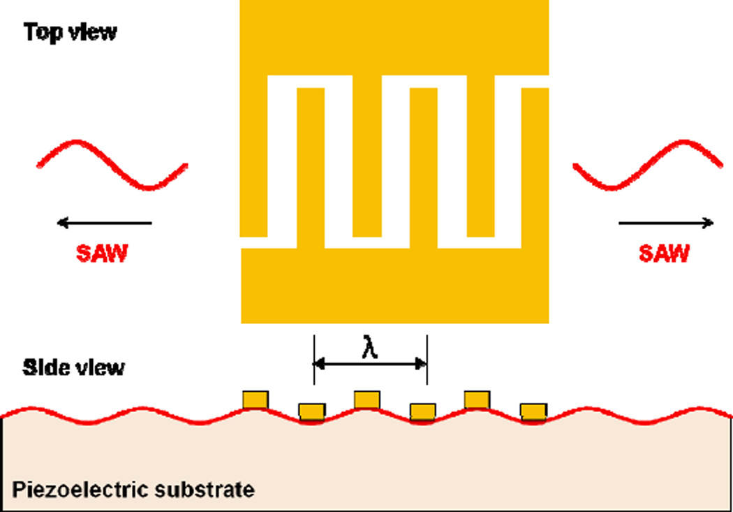
SAWs are generally produced by applying an appropriate electric field to a piezoelectric material. The piezoelectric material, in turn, generates propagating mechanical stress. A typical SAW device uses at least one set of metallic interdigital transducers (IDTs) fabricated on the surface of a piezoelectric substrate. The IDT then introduces the electric field, generating a SAW displacement amplitude on the order of 10 Å. An IDT consists of a set of connected metallic fingers interspaced with an opposite set of connected metallic fingers; an alternating current electrical signal in the radio frequency (RF) range is applied across the two sets of connected fingers (Fig. 1). The structure of the IDT determines the bandwidth and directivity of the generated SAW. By changing the number, spacing, and aperture (overlapping length) of the metallic fingers, one can change the characteristics of the resulting SAW. For example, a focused IDT consists of pairs of annular electrodes that can focus SAW energy to a spatially small focal point.40 A chirped IDT has a gradient of the electrode finger width directed along the SAW propagation direction, allowing it to generate SAWs over a wide frequency range.29 A slanted finger IDT has a gradient of electrode finger width directed perpendicular to SAW propagation direction, allowing it to generate narrow SAW beams of varying frequency along its finger length.41 Each IDT variant has its own set of advantages and disadvantages and the choice of IDT type for use in a SAW-based microfluidic device depends on the device requirements. Additional IDT design types will be discussed in the later portion of this review article.
Fig. 1.
A metallic IDT deposited on the piezoelectric substrate generates SAWs that propagate along the substrate surface in both directions.
Generation of SAW on a piezoelectric material can be mathematically modeled, but is complicated by (1) the anisotropy exhibited in most piezoelectric materials and (2) the intrinsic electromechanical coupling in piezoelectric media. The anisotropy of a piezoelectric material dictates whether the piezoelectric material generates shear-horizontal SAW,42 leaky SAW,43 or psuedo-SAW.44 As such, consideration must be given to anisotropy to ensure the generation of the desired type of wave. The full mathematical modeling of SAW propagation requires the analysis of the link between electrical signal and deformation in piezoelectric media, referred to as electromechanical coupling. The constitutive equations governing the linear theory of wave propagation in piezoelectric material are as follows:45
| (1) |
| (2) |
where Skl are the components of strain tensor, Ek is the electric field, eikl are the components of the piezoelectric stress tensor, are the dielectric constants at constant strain, and are the elastic moduli.
2.1.2 Generation of SAW-induced streaming
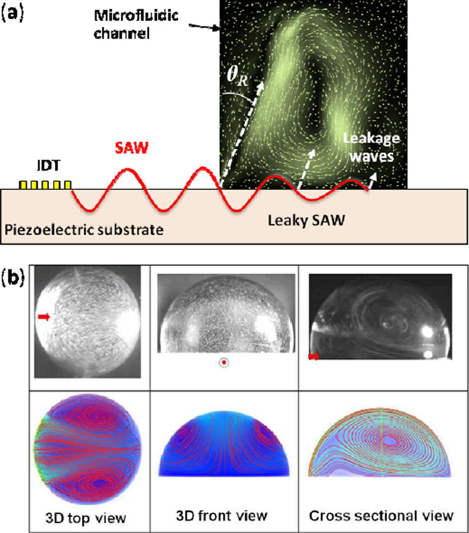
When a travelling SAW contacts a liquid, the liquid’s increased viscosity, relative to the substrate, causes part of the SAW to refract into the liquid as a longitudinal wave. Because of this acoustic refraction, the mode of SAW changes to a form called “leaky SAW” or “pseudo-SAW”. As shown in Fig. 2a, a SAW is excited by the IDT and propagates from left to right along the piezoelectric substrate surface within the depth of a single wavelength.46 The refracted wave moves along the direction given by a refraction angle known as Rayleigh angle:
| (3) |
where cs and cl denote the acoustic wave velocities of the piezoelectric substrate and the fluid, respectively. For a SAW propagating on a 128° Y-cut lithium niobate (LiNbO3) substrate at room temperature, the SAW velocity of about 3990 m/s47 and the speed of sound in water of 1490 m/s result in a Rayleigh angle of about 22°. The refracted longitudinal waves generate a force in their propagation direction and induce flow within the confined liquid. The boundaries of the confined liquid reflect the actuated liquid and lead to internal streaming. Such a non-linear phenomenon that transforms the SAW attenuation into a steady fluid flow is called SAW-induced acoustic streaming.48–56
Fig. 2.
SAW-induced acoustic streaming. (a) Rayleigh SAW is excited by means of an IDT. Underneath a liquid, the SAW turns into a leaky SAW, radiating pressure waves at the Rayleigh angle ΘR into the fluid. The streaming map is from Koster. Reprinted with permission from ref. 46. (b) Comparison of experimental results and numerical modeling for a hemispherical droplet positioned at the center of the SAW propagation direction. Reprinted with permission from ref. 52.
Here we provide a brief summary of the theory involved with SAW-induced streaming. Because the full physical process of SAW-induced streaming involves a coupled system of elastic, electromagnetic, and hydrodynamic effects,57 a comprehensive examination of its theoretical aspects is beyond the scope of this review. We instead examine the flow motion separately from the SAW that generates the flow in order to simplify the otherwise complicated physics of this phenomenon.
SAW-induced acoustic streaming can be visualized by introducing small particles or dyes into the effected liquid. The experimental and numerical results in Fig. 2b show a typical view of SAW streaming patterns within a hemispherical microdroplet positioned at the center of the SAW propagation direction.52 The SAW-induced streaming pattern varies dramatically with the shape of the confined liquid, as well as the incident position, angle, and the operating frequency of the SAW.55 Mathematical models, based on the compressible Navier-Stokes equations and numerical simulations of SAW-induced streaming, have been investigated by Vanneste et al.51 for liquid confined in a rectangular space and by Alghane et al.52 for droplets.
The principles of mass and momentum conservation that govern the motion of continuous media, for a linear viscous compressible fluid, yield the following set of governing equations:58, 59
| (4) |
| (5) |
where ρ is the mass density, u is the flow velocity, p is the fluid pressure, μ and μBare the shear and bulk dynamic viscosities, respectively. These equations allow one to predict the motion of the fluid when complemented by adequate sets of boundary conditions and a fundamental relation linking the behavior of the pressure p to that of the mass density ρ. In many applications, p and ρ are assumed to be linearly related:
| (6) |
where c0 is the speed of sound in the fluid at rest. Equations (4–6) form a nonlinear system of equations whose solution can be challenging, especially when focusing on behavior driven by the high-frequency oscillations imposed by SAWs. Since the fluid is a dissipative system, the response to harmonic forcing is not, in general, harmonic. It is convenient to think of the motion induced by harmonic forcing as having two components: (i) a harmonic, or more generally periodic, component with period equal to the forcing period; and (ii) remainder which can, in turn, be viewed as having a steady component and, possibly, a harmonic component with frequency double that of the forcing. The first component of the motion is the fluid’s acoustic response. The second component is the streaming motion. The acoustic component of the velocity is often referred to as the particle velocity, although this sort of vocabulary does not agree with the rigorous notion of particle velocity in continuum mechanics.
When the velocity of the acoustic component is dominant relative to the velocity of the streaming component, the streaming is called slow. Conversely, when the streaming velocity is of the same order or larger than the acoustic component, the streaming is called fast. While the decomposition of the motion into acoustic and streaming components, and the corresponding distinction between slow and fast streaming are conceptually straightforward, defining rigorous analytical and computational methods to separate these two components is still “a work in progress.” In fact, from a strictly mathematical viewpoint, the only theory that is on a rigorous foundation is that for slow streaming. This theory is based on an asymptotic expansion approach58 in which fluid velocity, density, and pressure fields are assumed to have the following form:
| (7a) |
| (7b) |
| (7c) |
where ε ≪ 1 is a non-dimensional smallness parameter defining the order of the acoustic response, the latter being represented by the quantity ũ1 = εu1. In slow streaming, the streaming velocity ũ2 = ε2u2 is assumed to be of second order, relative to the acoustic velocity ũ1. The parameter ε is typically taken to be the acoustic Mach number given as ε = |ũ1/c0. Köster defines the smallness parameter as the ratio between the amplitude of the displacement of the boundary in contact with the SAW device (i.e., the amplitude of the boundary excitation) and a characteristic length.57 From a strictly analytical viewpoint, this definition is appealing in that it is less tautological and directly related to the boundary data. This latter fact is crucial to the establishment of a mathematically rigorous development of the boundary conditions for the boundary value problems that the expansion in Eqs. (7) is meant to generate (see also Bradley,60 although Bradley uses the acoustic Mach number as smallness parameter). Using the expansion in Eqs. (7) to a first-order approximation, the first-order continuity and Navier-Stokes equation can be derived as:
| (8) |
| (9) |
The above equations allow the determination of the acoustic motion of the system. As is typical in progressive approximation methods, the acoustic solution is used for the determination of the streaming motion by substitution into the second-order equations. The latter, following a time averaging over a period of excitation, have the following form:
| (10) |
| (11) |
where 〈x〉 denotes the time average of the quantity x over a full oscillation time period.61 Both the first and the second order problems are, effectively, Stokes problems (the second-order problem has also mass sources and body forces). The boundary conditions for the above sets of equations depend on the type of the device. An in-depth discussion of the boundary conditions can be found in Bradley’s work.60 Further analysis and details are presented in Köster’s work.57 From a computational viewpoint, the complexity inherent in the original nonlinear problem is overcome by the solution of two linear problems in succession. With this in mind, the applicability of the solution is limited to the requirement that the series in Eqs. (7) be convergent, that is, that the streaming solution be an infinitesimal of one order higher than the acoustic solution when the smallness parameter goes to zero. It is this assumption that, from a mathematical viewpoint, defines slow streaming. However, experimental investigations have revealed that in some cases the streaming velocity can be of the same order of magnitude as the particle velocity. Thus, the fast streaming case demands another method to decompose the fluid velocity, density, and pressure fields to overcome the limitations of the perturbation approach. Zarembo employed the following decomposition of fluid fields into a time-averaged steady component and a periodic acoustic component (with zerotime averaged value):62
| (12a) |
| (12b) |
| (12c) |
This decomposition allows for the magnitude of the streaming velocity to exceed that of the particle velocity, and can thus be used to model fast streaming. Substitution of Eqs. (12) into Eqs. (4–6), followed by time averaging over an excitation period produces a set of nonlinear equations that can be solved for the streaming motion, provided that a solution is available for the acoustic motion. A discussion of how the equations for the determination of the acoustic motion are derived is offered by Friend and Yeo,31 who also include a discussion on the use of a nonlinear version of the constitutive relation in Eq. (6). However, the derivations of the equations in question cannot be said to have received the same level of attention as those for the slow streaming case.
2.1.3 Acoustic radiation pressure
When a travelling SAW contacts a small volume of liquid, the liquid absorbs part of the SAW’s energy and refracts it in the form of longitudinal waves. As described in Section 2.1.2, this refracted acoustic energy induces flow in the fluid, known as SAW-induced acoustic streaming. This refracted acoustic energy then acts on the fluid medium and any particles present in the fluid. This interaction is termed acoustic radiation pressure.
The notion of acoustic radiation pressure is a central concept in nonlinear acoustics. It should be clarified that the use of the word pressure is a bit of a misnomer in that the quantity called acoustic radiation pressure is actually a force and, as such, a vector quantity. Before introducing a formal definition of acoustic radiation pressure, it is important to stress the fact that the concept is meaningful when dealing with time-dependent phenomena in which there is a separation of time scales such that slow and fast dynamics are present. The acoustic radiation force is borne out of the time-averaging operation over the fast time scale to produce an effect that is relevant at the slow time scale.
Let R(t) be a generally time-dependent domain (e.g., a sphere) within the fluid under consideration. Let S(t) denote the bounding surface of R(t), oriented by an outward unit normal n. The Cauchy theorem from continuum mechanics states the force acting on S(t) is:
| (13) |
where σ = −pl + μ(∇u + ∇uT) + (μB −2μ/3)(∇ · u)I is the (Cauchy) stress in the fluid. Since the fluid is excited harmonically and the time scale of the harmonic oscillations can be much smaller than that of the resulting streaming flow, it is reasonable to compute the time average of the force in Eq. (13) over the fundamental period of harmonic excitation:63
| (14) |
This acoustic radiation “pressure” is experienced by the domain R(t). Using the assumptions underlying the expansion in Eqs. (7), it is possible to show that Eq. (14) can be written as:
| (15) |
where σ2 is the second-order stress, 〈ρ0u1⊗u1〉 is the so-called Reynolds stress, and S0 is the unperturbed configuration of S(t). The above expression represents the generalized equation for acoustic radiation pressure, and can be specialized to specific geometries and circumstances (e.g., the interaction of an acoustic wave with a single particle). Eq. (15) is essentially identical to that obtained in several other contexts in mechanics when dealing with time averaging over a fast time scale. Most notably, it is closely related to the notion of virial stress found in molecular dynamics.64,65
While Eq. (15) describes acoustic radiation pressure generally, the acoustic radiation force on an incompressible particle was first derived by King66 and was later extended for compressible particles by Yosioka and Kawasima.67 These works were further generalized by Gorkov.68 Using Gorkov’s approach, the primary acoustic radiation force on a small, spherical particle in an inviscid fluid has been derived as:69
| (16a) |
| (16b) |
| (16c) |
where, again, the angle brackets denote time averaging over an excitation cycle, a is the radius of the particle, c0 is the speed of sound in the medium, β0 and ρ0 are the compressibility and the density of the fluid, and βp and ρp are the compressibility and the density of the particle, respectively. A perturbation approach similar to Eq. (7) was utilized to derive Eqs. (16).70 Eqs. (16) are valid only for an inviscid fluid. Expressions for a viscous fluid can be derived using the general description of acoustic radiation pressure, Eq. (15).63
All of the above discussion regarding acoustic radiation pressure describes the force acting on a single particle that is present in fluid subjected to a SAW. If there are other particles contained in this same fluid, then acoustic interactions with these other particles will generate additional secondary forces on the particle being examined.69 The net effect of these primary and secondary acoustic radiation forces is to move a particle towards either the pressure node or the pressure antinode, depending on the mechanical properties of the particle.71
It is important to note that these particles will be subjected to both a net acoustic radiation force and a force from the SAW-induced fluid streaming. Which force dominates is dependent on the size of the particle: particles with dimensions above a particular size threshold will have their motion dictated by the acoustic radiation force. Barnkob et al. found that the size threshold is dependent on factors such as actuation frequency, acoustic contrast factor, and kinematic viscosity.72 Size threshold was demonstrated, both computationally and experimentally, to be 1.4 µm for polystyrene beads subjected to an acoustic frequency of 2 MHz in water.
2.2 Microfluidic Technologies Enabled by TSAWs
In this section, we review the application of TSAWs in both open and confined microfluidic geometries to accomplish (1) fluid mixing, (2) fluid translation, (3) jetting and atomization, (4) particle/cell concentration, (5) droplet and cell sorting, and (6) re-orientation of nano-objects. These examples demonstrate the growth of TSAW into a key component for many emerging on-chip applications.
2.2.1 Fluid mixing
Many lab-on-a-chip applications require the mixing of two or more fluids. However, the laminar flows that predominate at the micro-scale result in mixing that occurs via diffusion. Such diffusion-based mixing is too slow for most lab-on-a-chip applications, so researchers have looked to SAW-induced streaming for its ability to mix fluids quickly by generating chaotic advection.
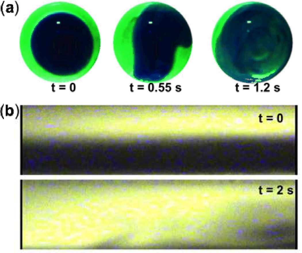
A few groups have demonstrated methods using TSAWs to mix fluids in an unconstrained droplet. Shilton et al.56 generated a TSAW using a single-phase unidirectional transducer (SPUDT) to induce liquid recirculation inside a droplet. Their results, shown in Fig. 3a, demonstrate the fast mixing of dyed water and dyed glycerine solution. Frommelt et al.73 demonstrated a more refined TSAW-based droplet mixing, using a pair of tapered IDTs (TIDTs) to generate a narrow SAW beam with a tunable launching point. By individually modulating the input signals of the two TIDTs, they demonstrated the ability to temporally modulate the flow patterns generated by each IDT to achieve efficient mixing. They also demonstrated that they could control mixing speed (within the droplet) by adjusting SAW amplitude and frequency.
Fig. 3.
Fluid mixing by SAW-induced acoustic streaming. (a) Rapid mixing of glycerine (light) and water (dark) in a droplet. (b) Mixing of fluorescence dyes (light) with water (dark) in a rectangular microfluidic channel. Reprinted with permission from refs. 73 and 54.
Tseng et al.54 also used IDTs to demonstrate TSAW-based mixing. Instead of mixing fluids in an unconstrained droplet, they mixed fluids inside a microchannel (Fig. 3b). They performed a comprehensive experimental study on the effects of various operational parameters, showing that mixing performance could be significantly improved by applying higher voltage signals to the IDTs. Luong et al.74 used a curved IDT design to focus the generated acoustic energy, resulting in considerably improved mixing performance relative to the parallel IDT design employed by previous groups.
Recently, Rezk et al.75 incorporated SAW-induced mixing in a paper-based microfluidic device. They utilized a hue-based colorimetric technique to compare the mixing efficiency of their device with that of capillary-based mixing: the SAW-based mixing showed greatly enhanced consistency and speed.
By adjusting IDT design and input signal parameters, researchers have proven that TSAWs can effectively and precisely mix fluids in both open and confined fluid geometries. This versatility makes TSAW-based mixing techniques extremely attractive in microfluidics.
2.2.2 Fluid translation
2.2.2.1 Fluid translation in open space
When a liquid droplet is placed within the propagation path of TSAWs on a piezoelectric substrate, leaky SAW will be diffracted into the droplet at the Rayleigh angle. If the SAW has low amplitude, it will induce acoustic streaming within the droplet. If the SAW has sufficiently intermediate amplitude, the leaky acoustic energy generates an acoustic force on the droplet along the SAW propagation path, causing the droplet to deform into an axisymmetrical conical shape and translate across the substrate.49,76 Liquid droplet speeds of 1–10 cm/s can be achieved using this TSAW-based actuation; this is more than an order of magnitude faster than other current micro-pumping actuation schemes.32
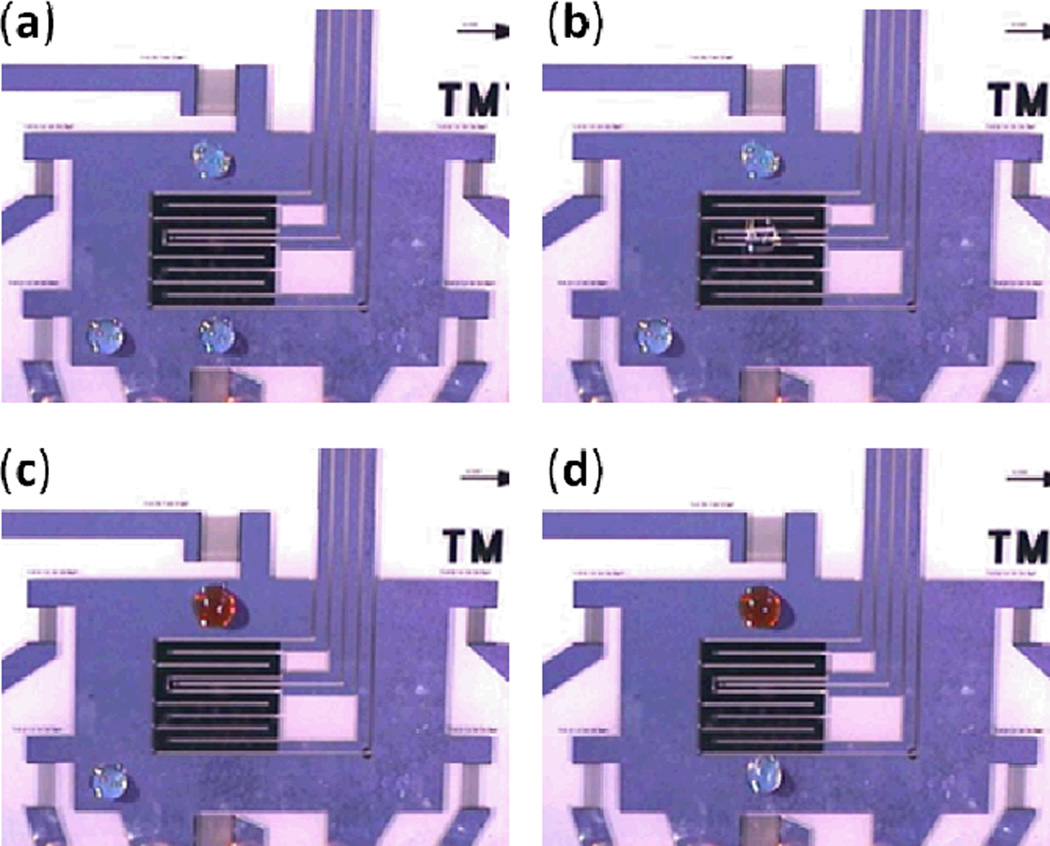
Moreover, as electrical actuation of IDTs can be programmed, droplet movements can be automated. Through the automated control of multiple droplets, merging, mixing, splitting, and chemical or biochemical reactions can be performed in so-called “programmable bioprocessors”. A simple example of a programmable bioprocessor is shown in Fig. 4, in which three droplets with different fluid content are moved independently in any desired direction and can be made to join together.78
Fig. 4.
TSAW-driven programmable bioprocessors. (a—d) Three droplets are moved individually and with precise control. Reprinted with permission from ref. 78.
Many chemical and biological applications have been demonstrated with TSAW-driven droplets. Guttenberg et al. precisely actuated oil-covered aqueous droplets between sinkers and heaters to perform a highly sensitive, fast, and specific DNA amplification reaction with droplet volumes as low as 200 nL.79 Similarly, Tan et al. rapidly and effectively collected and removed micro-particles using this TSAW-driven droplet translation technique.80 Finally, Li et al. used a similar mechanism to transport cells into tissue scaffolds to enhance cell seeding for tissue engineering studies.81
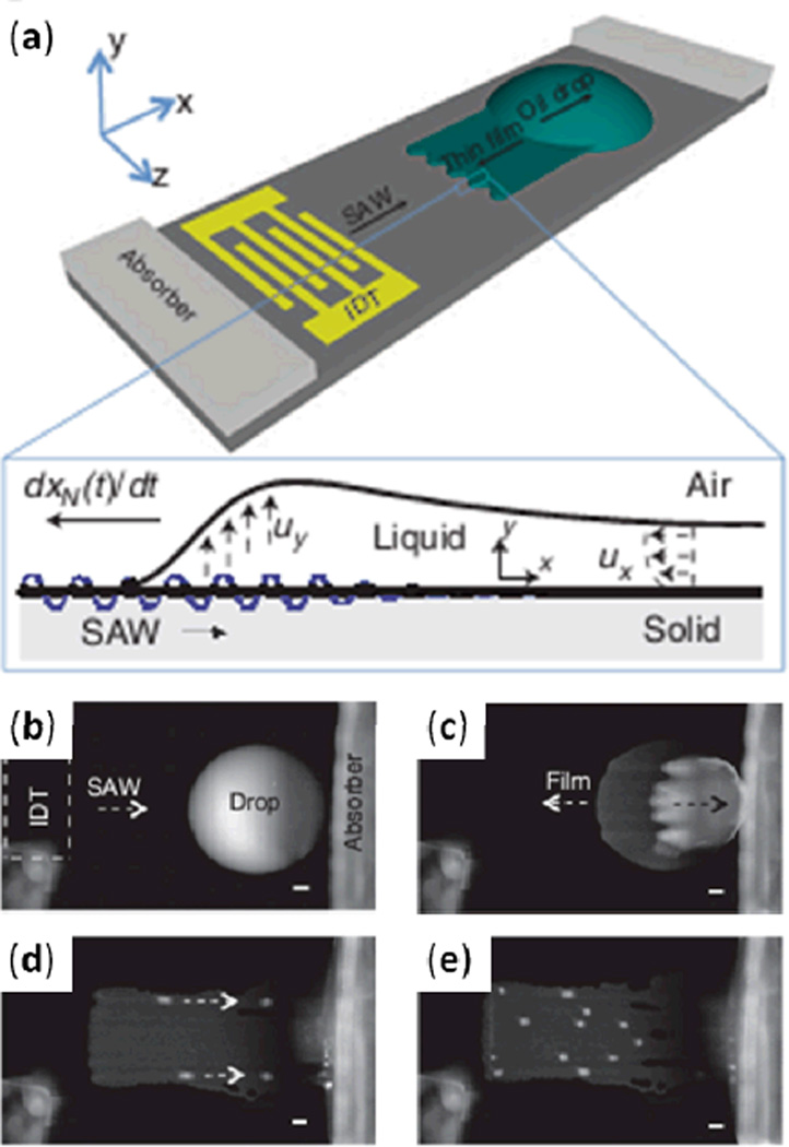
Rezk et al. subjected a droplet of silicone oil to TSAW excitation, observed behavior substantially different from that of water droplets, and developed theory for the behavior (Fig. 5a).82 Silicone oil has a much smaller contact angle with a LiNbO3 piezoelectric substrate than does water. When a silicone oil droplet on such a substrate was exposed to TSAW, this small contact angle led to a majority of the droplet being propelled in the SAW propagation direction (Fig. 5b), while a thin film spread in the opposite direction (Fig. 5c). As the thin film advanced, it formed finger-shaped patterns (Fig. 5d); eventually, soliton-like wave pulses appeared above the fingers and propagated along the TSAW direction (Fig. 5e). The authors suggest that this TSAW-induced thin film spreading may have applications in film coating and microfluidic actuation.
Fig. 5.
(a) Schematic of experimental setup depicting the emergence of a thin film from a standing oil drop due to TSAW exposure. (b) Initial state of the oil droplet. (c) After excitation with TSAW, the bulk of the oil droplet is displaced along the SAW propagation direction while a thin oil film advances in the opposite direction. (d) Finger patterns form in the thin film. (e) Soliton-like wave pulses subsequently appear above the fingers and translate in the SAW propagation direction. Reprinted with permission from ref. 82.
Historically, most SAW microdevices have been fabricated on bulk LiNbO3 or quartz substrates; these bulk piezoelectric substrates may require some extra processing in order to integrate control electronics (e.g., for the IDTs). To facilitate further advancements in SAW microfluidics, Du et al. presented a thin film piezoelectric material for translation of liquid droplets with volumes up to 10 µl.53 They first deposited a ZnO thin film on a plain silicon substrate. This hydrophilic ZnO thin film layer prevents effective droplet translation. To circumvent this, they treated the ZnO thin film with a self-assembled monolayer of octadecyltrichlorosilane (OTS), which made the substrate surface hydrophobic while producing no measurable acoustic damping. The new substrate is cheaper than bulk piezoelectric substrates, and the silicon base can easily be integrated with control electronics for the IDTs, enabling the potential for a fully automated microsystem.
2.2.2.2 Microfluidic pumping in enclosed channels
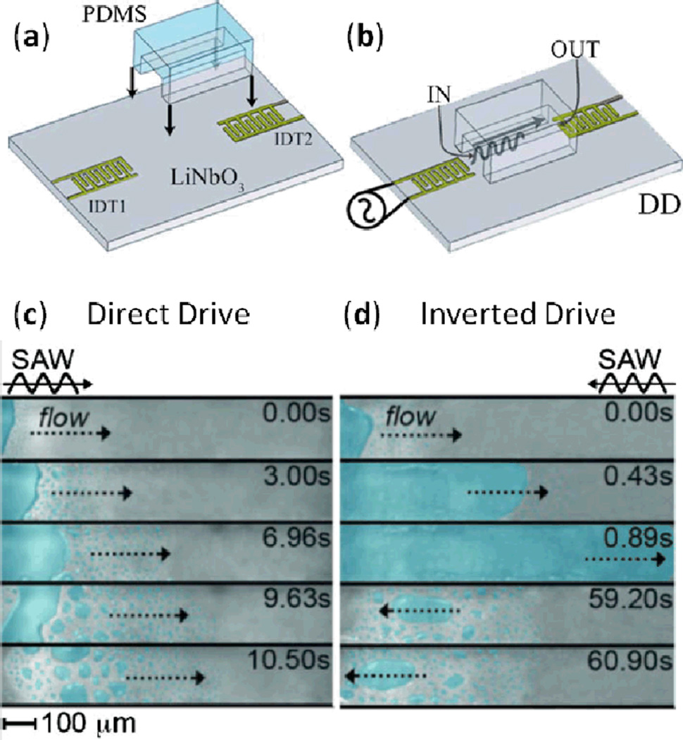
In addition to translating liquid droplets in open space, TSAWs can be employed to pump fluid through enclosed channels.83–89 Cecchini et al.86 bonded a straight PDMS microchannel between two IDTs on a LiNbO3 substrate (Fig. 6a). After placing a water droplet between one IDT and the channel inlet (this droplet was termed the water “reservoir”), two different operation modes were tested: direct drive mode and inverted drive mode. In direct drive mode, SAWs were excited by the IDT near the channel inlet and propagated from inlet to outlet (Fig. 6b), whereas inverted drive mode had SAWs excited by the IDT near the channel outlet and propagated from outlet to inlet. In direct drive mode, SAW excitation caused significant atomization in the water reservoir, resulting in rapid evaporation of the water and preventing the channel from being filled (Fig. 6c). In inverted drive mode, the water reservoir quickly translated into the microchannel, filling it at a flow speed as high as 1.24 mm/s. The authors propose that this flow rate, occurring opposite the TSAW propagation direction, is attributable to TSAW-induced atomization at the leading edge of the water. These droplets continuously form, coalesce, and rejoin the water-air meniscus, thereby dragging the water through the channel and resulting in net motion opposite the direction of TSAW propagation (the water reservoir is not exposed to significant atomization under the inverted drive configuration because the TSAW power is sufficiently diminished by the time it reaches the reservoir location at the channel inlet).
Fig. 6.
(a) Schematic of the assembly of the microfluidic device and (b) activation of IDT1, called direct drive (DD) mode; activation of ID2, called inverted drive (ID) mode, results in TSAW propagation opposite that shown in this image. (c) Photographs of the (ineffective) water filling process under DD mode at different times. (d) Photographs of the water filling process under the ID mode at different times. Reprinted with permission from ref. 86.
Based on this TSAW inverted drive mechanism, Girardo et al.87 developed a fully controlled low-voltage micro pump in a two-dimensional microchannel array. By combining a 5×5 orthogonal array of PDMS microchannels on a LiNbO3 substrate with 20 IDTs, the researchers could selectively generate either a single TSAW or multiple TSAWs. Thus, droplets at channel inlets could be directed through the microchannel grid to the desired outlets. This device achieved several SAW-driven fluid operations including extraction, deviation, splitting, and simultaneous multichannel filling.
TSAW-driven pumping has also been demonstrated in a closed microfluidic channel (with no liquid-air interface) by Fallah et al.88 This device featured a microfluidic channel in a square-shaped loop, with an IDT to generate SAWs travelling along one of the four sides. When a TSAW reaches the fluid-substrate interface, the acoustic energy leakage profile decays exponentially with continued wave travel along the fluid channel. With a sufficiently long channel, the location of initial TSAW contact with the fluid essentially acts like a point pressure source, driving the fluid through the channel loop according to conservation of mass. With this setup, fluid flow could be continuously actuated with very fast response. Fluid pumping in such a closed-loop chamber can be used to mimic the action of small blood vessels, making it useful for clinical applications and biomedical studies.83,84,89
2.2.2.3 Microfluidic rotational motor
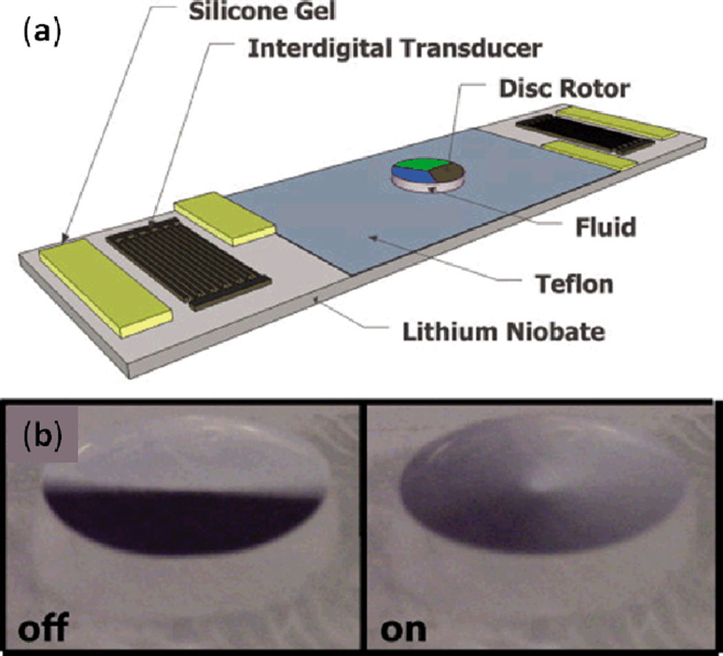
Shilton et al. utilized SAW-induced acoustic streaming to drive a rotary micromotor in a microfluidic chip (Fig. 7a).90,91 A pair of IDTs were patterned on a LiNbO3 substrate, and a layer of hydrophobic Teflon film was coated in the space between the two IDTs in order to hold a fluid droplet in place. Silicone gel was placed on the SAW’s path to absorb half of the energy from each IDT, creating a centrosymmetric TSAW exposure in the droplet, which resulted in centrosymmetric acoustic streaming inside the droplet. When a Mylar disc with 5 mm diameter and 100 µm thick was placed on top of the droplet, the droplet’s rotational inertia actuated rotational motion in the disc (shown in Fig. 7b). The disk’s angular velocity under a range of SAW amplitudes was investigated. In the case in which a 50 µl water drop was used as the fluid-coupling layer, a maximum disk rotation speed of 2250 rpm was achieved with a maximum torque of around 69 nNm. The authors found that increasing SAW amplitude to surpass ~3 nm would reduce angular speed due to the unstable disc rotation caused by asymmetric flow in the drop.
Fig. 7.
(a) Schematic of the SAW-induced rotary micromotor. Silicone gel was used to break the axisymmetry of the planar SAW and generate a centrosymmetric SAW, resulting in centrosymmetric acoustic streaming inside the drop. (b) The static and spinning states of the Mylar disc placed on top of the drop. Reprinted with permission from ref. 90.
By replacing the original Mylar micromotor with a patterned disk, Glass et al. successfully used this setup as a miniaturized lab-on-a-disc.92 These discs were patterned with microfluidic channels, enabling SAW-induced microcentrifugation. With this setup, the authors demonstrated functions such as capillary valving, mixing, and particle concentration and separation.
As described in the above examples, SAW-induced acoustic streaming enables a simple and miniaturized on-chip rotational motor without the need for moving mechanical parts. In future studies, researchers will likely examine fluid-coupling layers other than water in order to circumvent the potential for evaporation.
2.2.3 Jetting and atomization
A fluid jet is commonly defined as a coherent stream of fluid projected into a surrounding medium. For a fluid to undergo jetting phenomena, it must possess sufficient inertia to overcome the restoring capillary forces acting on the interface of the fluid and surrounding media.31,93 Jetting at micro-scales finds numerous applications in hand-held ink jet printers, ink jet highlighters, and ink jet brushes.94,95 Such micro-scale jetting can be accomplished by exposing small fluid volumes to TSAW (with the SAW power higher than that used for droplet translation). Recent research has demonstrated that SAW-based fluid jet production offers benefits over existing jetting techniques as it concentrates mechanical energy into a small drop, generating jets without the narrow confinement typically necessary to accelerate fluid.
Recently, Tan et al.96 studied the nature of jet formation using TSAW devices, as shown in Fig. 8. They characterized jetting length as a function of the driving force and the jet Weber number. They also predicted the jet’s velocity as a function of acoustic Reynolds number using the jet momentum equation of Eggers,93 and verified their results with the experimental data. These rigorous characterization efforts have helped to facilitate future TSAW-based jetting technologies.
Fig. 8.
Jetting generation resulting from exposure to travelling SAW. Reprinted with permission from ref. 96.
Atomization is the making of an aerosol of small solid particles or liquid droplets. It has long been applied in numerous areas, such as internal combustion engines, medicine, agriculture, and cosmetics.97 Kurosawa et al. first proposed and constructed a novel ultrasonic atomizer using a TSAW device.98 Since then, SAW-based atomization has been used for numerous applications such as protein extraction and characterization for paper-based diagnostics,99 portable pulmonary delivery of asthmatic steroids,100 and mass spectrometry interfacing with microfluidics.101,102 Qi et al.103 proposed a miniature inhalation device based on SAW atomization, and Ho et al.104 merged SAW atomization with a paper-based sample delivery system to detect the presence of caffeine in human whole blood.
TSAW atomization has also been utilized for producing micro and nano particles. Alvarez et al.105 demonstrated the generation of protein aerosols and nanoparticles using SAW atomization, while Friend et al.106 utilized a similar technique to synthesize polymeric nanoparticles. The small footprint of its generating mechanism, low power consumption, biocompatibility, and control over aerosol size make SAW an attractive method for atomization and a potential enabler for next-generation drug delivery devices.
TSAW-induced atomization is a result of capillary waves on the air-liquid interface.107 The mathematical analysis of this phenomenon is challenging due to the presence of a free interface and a non-linear, two-dimensional wave interaction coupled with vastly varying time scales. Despite the associated difficulty, numerous efforts have been made to understand this phenomenon from a theoretical perspective. Köster et al.57 used a perturbation approach to investigate flow field inside a droplet, while Dong et al.108 approached the problem by solving three-dimensional Navier-Stokes equations using a volume-of-fluid method to determine the free interface. Tan et al.109 used a coordinate transformation approach to model the deformation of the interface, deriving the bulk deformation and unsteady capillary wave from the most basic principles, thus allowing their approach to correctly calculate acoustic wave reflections. Most recently, Collins et al.110 investigated the hydrodynamics associated with SAW atomization, and developed a model for thin film spreading behavior under SAW excitation. Despite recent progress in describing the physics governing SAW-induced atomization, much remains to be understood.
2.2.4 Particle/cell concentration
Concentrating particle/cell suspensions is a basic but critical operation in many applications in chemistry and biomedicine. On the macro-scale, particles can be easily concentrated using centrifugation. On the micro-scale, however, concentrating cells or particles can be difficult. As volume decreases, surface forces acting on the particles/cells begin to dominate over body forces. Lack of significant body forces makes standard centrifugation impractical, so researchers have explored SAW-induced acoustic streaming to concentrate cells and particles for low-volume systems.56,111–113
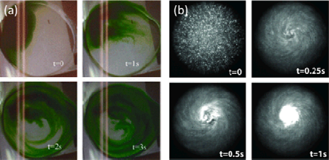
To initiate rotational fluid motion, Shilton et al.56 placed a droplet within a portion of a SAW propagation pathway in such a way that the droplet experienced TSAW exposure across a fraction of its width. This resulted in a circular pattern of SAW-induced acoustic streaming within the droplet (Fig. 9a). When microparticles in aqueous suspension were subjected to this rotational pattern of SAW-induced streaming, they were concentrated and deposited in the center of the droplet. The researchers attributed the concentration effects to a shear gradient between regions of high shear at the droplet’s periphery and regions of low shear at the droplet’s center. Particles tended to move towards the region of low shear, where the linear velocities of the fluid approached zero.
Fig. 9.
(a) Sequential images of rotational acoustic streaming in a drop resulting from asymmetric exposure to TSAWs, with flow streamlines visualized using dye. (b) Concentration of particles in a 0.5 µl droplet via such rotational acoustic streaming. Reprinted with permission from ref. 56.
Figure 9b shows sequential images of the SAW-induced streaming for a water sample containing 0.5 µm white fluorescent beads. The progression from distributed individual dots at t=0 to the central bright spot at t=1 s demonstrates how quickly the rotational SAW-induced streaming moves the fluid and concentrates the particles. In this way TSAWs allow for quick and efficient particle concentration at the micro-scale with a simple droplet-based device setup.
2.2.5 Droplet/cell sorting
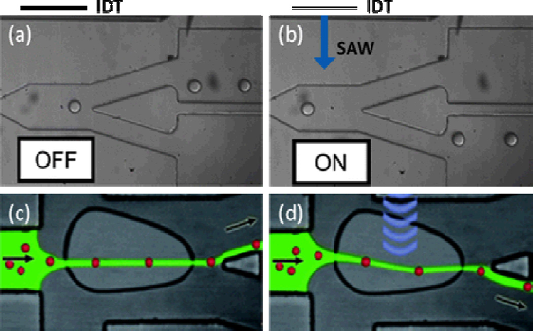
The ability to precisely sort individual droplets of interests from other droplets is extremely important for various chemical and biological screenings. Similarly, cell sorting is an important task for many disciplines, ranging from basic cell biology to clinical diagnosis. Recently, several groups have shown that SAW-induced acoustic streaming can selectively sort droplets or cells. The device used to accomplish this sorting consists of a branched PDMS channel and an IDT positioned adjacent to the channel that generates TSAWs propagating across the channel width. Either droplets or cells are injected into the main channel and hydrodynamically focused in its center before reaching the region of TSAW exposure.114,115 When the IDT is off, the droplets or cells travel through the upper outlet branch because of its larger cross-sectional area and correspondingly lower hydrodynamic resistance (Figs. 10a and 10c). When the IDT is powered, the resulting TSAWs generate acoustic streaming in the channel fluid and push the fluid, which carries with it the contained droplets or cells, towards the lower outlet branch (Figs. 10b and 10d). In this way, the device harnesses SAW-induced acoustic streaming to sort droplets or cells into two outlets. Recently, the same group used this TSAW propagation technique to modulate droplet generation.116
Fig. 10.
Schematic illustrations of the SAW-based mechanism for droplet or cell sorting. With the absence of SAW propagation through the main channel, (a) the droplets or (c) cells in the main channel move into the upper outlet channel due to its lower hydrodynamic resistance. With SAW exposure, acoustic streaming moves the fluid downward, carrying with it the contained (b) droplets or (d) cells and moving them to the lower outlet channel. Reprinted with permission from ref. 114 and 115.
2.2.6 Reorientation of nano-objects
2.2.6.1 Carbon nanotube alignment
Carbon nanotubes (CNTs) have been a focus of nanotechnology research for over two decades.117 Their mechanical strength and unique electrical properties make CNTs attractive for a wide variety of applications ranging from sports equipment to electronics. However, aligning large quantities of CNTs for use in these applications often proves challenging. TSAWs present a practical solution, allowing for the simultaneous alignment of many CNTs.
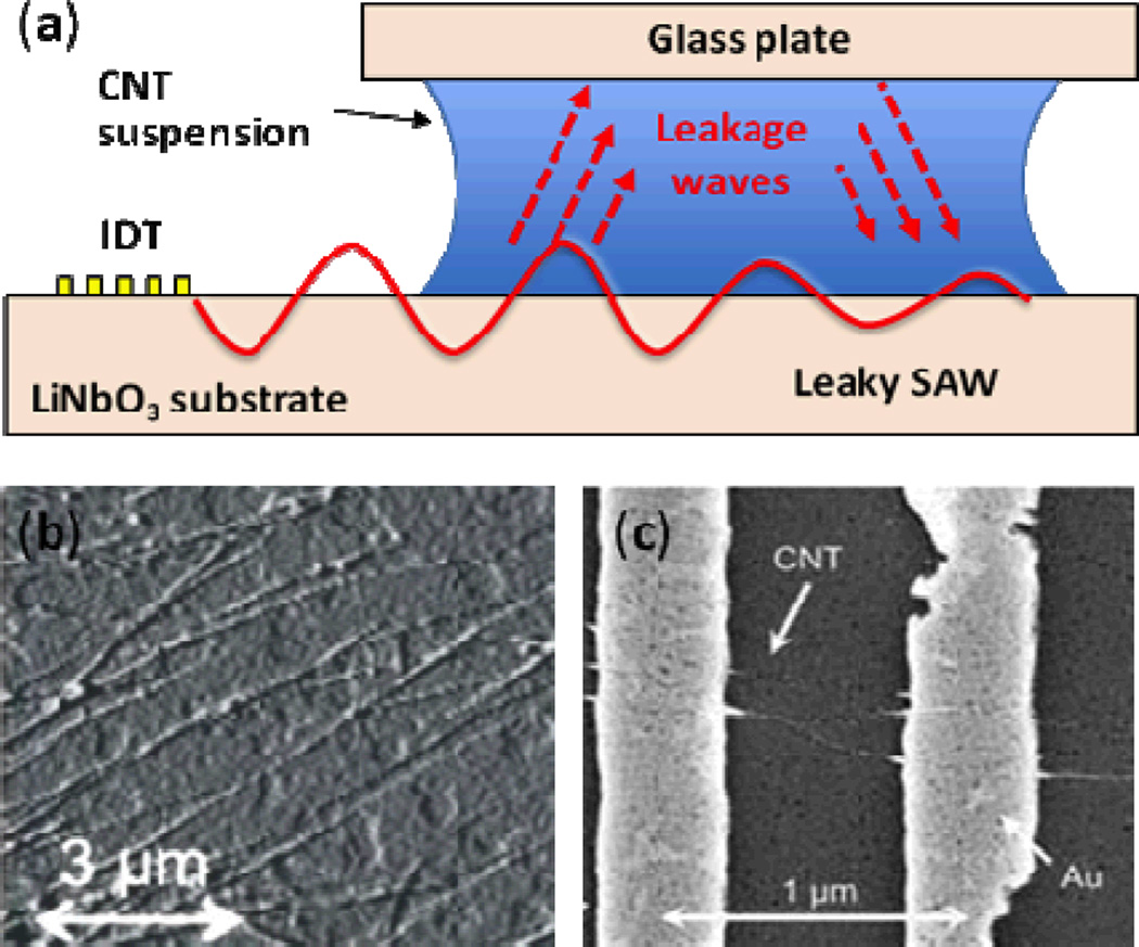
Strobl et al. demonstrated the alignment of multi-walled carbon nanotubes (MWNTs) on a LiNbO3 substrate using TSAWs.118 Figure 11a shows a typical setup for the SAW-induced nanotube alignment device. After activating the SAWs, the device aligned carbon nanotubes 25–45 degrees relative to the SAW field (shown in Fig. 11b). To discern between the effects of fluid movement and piezoelectric field in the alignment of these MWNTs, the authors covered the LiNbO3 substrate with a 20 nm layer of NiCr. This thin metallic film then screened the piezoelectric field of the TSAWs. Experiments conducted on this metal-coated substrate device yielded no observable alignment of the MWNTs. To confirm this observed alignment is dependent on the piezoelectric field, the authors then used a LiTaO3 substrate to propagate a shear-wave SAW (as opposed to the Rayleigh SAW propagated on a LiNbO3 substrate). The mechanical component of a shear-wave SAW exists in the plane of the crystal, yielding minimal fluidic coupling relative to that of Rayleigh SAWs. When using LiTaO3 substrate, the MWNTs aligned parallel to the SAW field, showing improved alignment relative to the LiNbO3 device. Thus the authors concluded that the MWNT alignment is attributable to the piezoelectric field associated with SAW propagation, and the acoustic streaming generated by Rayleigh SAWs actually shifted the MWNTs from being directly aligned with the piezoelectric field.
Fig. 11.
(a) Schematic of device setup for SAW-based carbon nanotube alignment. (b) AFM image of aligned multi-walled carbon nanotubes. Reprinted with permission from ref. 118. (c) SEM image of aligned single-walled carbon nanotubes between pre-patterned gold electrodes on LiNbO3. Reprinted with permission from ref. 119.
Smorodin et al. improved upon the alignment performance of the SAW-only approach by first thiolating single-walled carbon nanotubes (SWNTs) and then placing them on a substrate with patterned gold electrodes (Fig. 11c).119 By applying SAWs across this setup, the authors found that a majority of SWNTs aligned at angles between 0 and 20 degrees relative to the SAW field. They attributed this improvement to the rapid attachment of thiolated carbon nanotubes to the gold electrodes, reducing the impact of acoustic streaming on the nanotube alignment.
Though the previous studies demonstrated successful alignment of CNTs, their use of piezoelectric substrates limits their usefulness in microelectronics applications, as most microelectronic devices use non-piezoelectric silicon substrates. Seemann et al. used a “flip-chip” configuration to overcome this limitation, enabling the alignment of carbon nanotubes on silicon substrate.120 In the experiment, a silicon substrate was patterned with gold contacts and then brought into close proximity with a LiNbO3 substrate. A CNT solution was deposited to fill the space between the two substrates. Application of TSAWs to the CNT solution (by means of the LiNbO3 substrate) resulted in a combination of piezoelectric field and acoustic streaming effects that successfully aligned CNTs between the pre-structured gold electrodes on the silicon substrate.
2.2.6.2 Liquid crystal reorientation
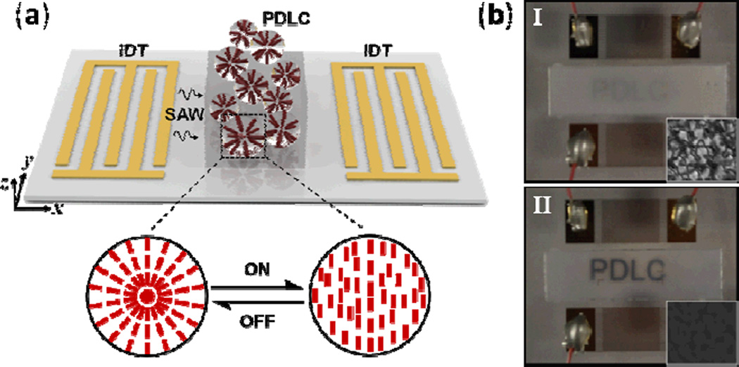
Polymer dispersed liquid crystals (PDLCs) consist of liquid crystal droplets randomly dispersed in a transparent polymer matrix. They are widely used in displays and optical elements, where the application of an electric field to the PDLCs readily adjusts the light transmittance through the material. In addition to PDLC realignment via an electric field, several reports have shown that liquid crystals can also be realigned using acoustics.121 Recently, Liu et al. reported a light shutter effect induced by TSAWs applied to PDLCs.122 As shown in Fig. 12a, PDLCs were placed between two IDTs on a LiNbO3 substrate. In this setup, one IDT generated SAWs and the other detected them. Results demonstrated that SAW-induced acoustic streaming successfully aligned PDLCs parallel to the SAW propagation direction, changing the PDLCs from opaque to transparent (Fig. 12b).
Fig. 12.
(a) The device structure and working principle for the SAW-driven PDLC light shutter. The magnified part shows a reversible switching process between two different liquid crystal droplet configurations. (b) Transmission response of the PDLCs under different acoustic powers. The insets I and II show the imaging quality at the off and on states of the IDT, respectively. Reprinted with permission from ref. 122.
During experimentation, SAW propagation on the substrate heated the PDLCs to 40°C. To verify that the PDLC realignment was attributable to SAW-induced acoustic streaming and not to thermal effects, the researchers set up an experiment using standing SAWs rather than TSAWs. This standing SAW field minimized the acoustic streaming effect while still heating the substrate and PDLCs; no PDLC realignment was observed. Therefore, the authors concluded that SAW-induced acoustic streaming is a viable actuation method for PDLC realignment.
Most recently, Liu et al. demonstrated the robustness of this effect by showing that application of a SAW field can also be used to control light transmission of holographic polymer-dispersed liquid crystals.123
2.3 Microfluidic Technologies Enabled by Phononic Crystal-Assisted TSAWs
2.3.1 Introduction to phononic crystals
In the past decade, there has been a tremendous growth of interest in two- and three-dimensional periodic structures due to their ability to manipulate the propagation of acoustic waves on the wavelength scale. These artificial periodic structures, known as phononic crystals (PCs), are composed of arrays of elastic scatterers embedded in elastic host materials with properties different from those of the scatterers. PCs exhibit several unique behaviors as a result of their structures. Of greatest interest are so-called “phononic band gaps”, which occur when phonon wavelengths correspond to the scale of the PC’s periodicity. In phononic band gaps, acoustic waves in any vibration mode cannot penetrate the PC’s structure in any direction due to destructive interference caused by phonon reflections from the periodic scatterers.124,125
The properties that result from PCs’ periodic structure allow them to function in a wide variety of applications. The predictable responses produced by phononic band gaps make PCs promising candidates for perfect acoustic mirrors and for acoustic filters at designated frequencies. Likewise, PCs can serve as resonators and acoustic waveguides because any defect in a PC will contain acoustic wave vibrations when operating within the phononic band gap. Most importantly, PCs can be used to achieve super-resolution acoustic imaging when they exhibit negative refraction (the phenomenon occurring at the interface of materials in which acoustic waves are refracted opposite to the typically expected refraction).126 Super-resolution acoustic imaging has been obtained because of the PC-based acoustic lens’ ability to overcome the diffraction limit. Recently, with the introduction of a gradient-index (GRIN) concept to PC, a new class of PC was born. GRIN PC adds the ability to bend, focus, and modify the aperture of an acoustic beam to the already powerful capabilities of PCs.127–131
PCs and GRIN PCs are considered the most promising candidates for solving low-frequency noise reduction issues and for providing ideal acoustic isolation for communication-band SAW devices. Moreover, the combination of PCs with SAW-based microfluidic devices can improve the performance of existing SAW microfluidic technologies and lead to novel applications. Though the field of PCs is still relatively new, it offers tremendous potential. In the following sections, we introduce a few examples of the successful technologies that arise from merging PCs with TSAWs.
2.3.2 Particle/cell concentration
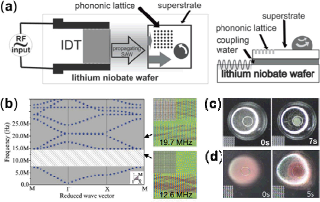
To accomplish particle concentration in a droplet on the surface of a superstrate, Wilson et al. exploited the absolute phononic band gap of a PC.132 As shown in Fig. 13a, an IDT was fabricated on a LiNbO3 wafer to generate TSAWs. A PC consisting of circular holes in a square array was designed to exhibit a wide phononic band gap and fabricated on a silicon wafer (Fig. 13b). When a SAW is generated at the proper frequency by the IDT, it travels along the surface of the LiNbO3 substrate, leaks into a water-coupling layer, and excites Lamb waves across the thickness of the silicon superstrate that propagate in the same direction as the SAWs. Half of the excited Lamb waves encounter and are reflected by the PC, and the other half travel through the superstrate undisturbed. Thus the water droplet experiences an asymmetric Lamb wave exposure, and an in-plane counter-clockwise acoustic streaming pattern is induced. Fig. 13c shows the induced circular acoustic streaming being used to focus small particles inside a droplet. The Cooper group also used this method to concentrate human blood cells from a diluted blood sample, demonstrating its applicability in biology and medicine (Fig. 13d).
Fig. 13.
(a) Schematic of SAW device using a superstrate with embedded PC. TSAWs generated by IDT on the LiNbO3 substrate leak into a water-coupling layer, inducing Lamb waves in the silicon superstrate that are then spatially filtered by the phononic lattice to provide asymmetric exposure to the droplet. (b) Left panel shows the band structure of the designed phononic lattice; the shaded area depicts the absolute phononic band gap. Right panel shows simulations at two different frequencies. (c) Concentration of 10 µm polystyrene beads at center of the droplet due to circular acoustic streaming. (d) Concentration of human blood cells at the center of the droplet. Reprinted with permission from ref. 132.
Despite the added complexity to the manufacturing processes, the use of PCs in acoustic streaming applications enables some notable advantages. For example, PCs with different design characteristics can be used to tune the frequency and amplitude of a single SAW, allowing users to program fluid manipulation without altering the input electrical signal. In addition, PCs and IDTs can be fabricated independently on separate units (e.g., substrates and superstrates, coupled by an intermediate fluid layer), enabling device configurability and disposability. Several studies have applied these advantages to create useful technologies. For example, Bourquin et al. combined droplet manipulation via acoustic streaming with a lens-free detection system to create a disposable device for immunoassay.133 Applying their immunoassay to tuberculosis diagnosis, the researchers detected Interferon ϒ at pM concentrations within minutes. Reboud et al. developed a sophisticated SAW-based fluid manipulation tool for the detection of rodent malaria parasite Plasmodium berghei in blood.134 Red blood cells and the parasitic Plasmodium berghei in a drop of blood were mechanically lysed via the strong acoustic rotation vortices generated by PC-aided acoustic streaming. The researchers then amplified the parasitic genomic sequence by heating the sample using different acoustic field and frequencies. Their results demonstrated that this PC-assisted device has the ability to detect around 0.07% parasite DNA in a microliter-size blood sample and, more broadly, that it has potential for disease diagnosis in the developing world.
2.3.3 Jetting and nebulization
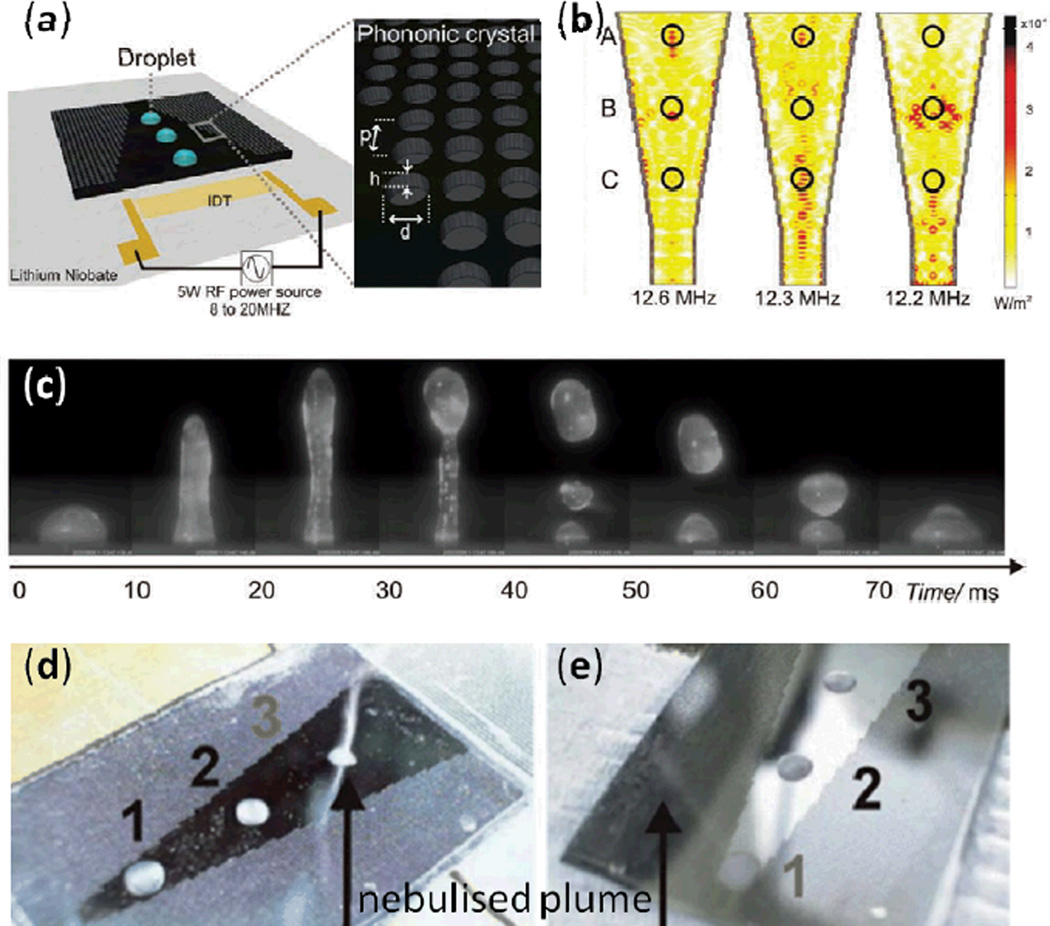
Recently Bourquin et al. reported an interfacial jetting phenomenon by fabricating a conic PC on a superstrate.135 Though jetting of a sessile droplet had been previously demonstrated using focused IDTs on a piezoelectric surface,100 it had not been shown on a superstrate. In this work, the authors forced a SAW in a piezoelectric substrate to couple with a superstrate and excite Lamb waves (Fig. 14a). The cone-shape design of the PC they used provided a means to effectively focus acoustic energy to different hot spots, depending on the frequency of the SAW, as shown in Fig. 14b. They used this spatial control of acoustic energy to dictate the location and direction of the interfacial jetting behavior; Fig. 14c shows that this focused acoustic energy can efficiently produce interfacial jetting phenomenon.
Fig. 14.
(a) Schematic of the SAW-induced interfacial jetting device. (b) Simulations of the conic structure at three different input frequencies. The waves are focused at different positions depending on the frequencies. (c) Continuous microscopic images of the jetting phenomenon on a PC superstrate for a sessile droplet of 10 µL. The drop elongates to form a column of water and breaks up into droplets. Images in (d) and (e) show, alternately, drops at position 3 (excited at 12.6 MHz) and position 1 (excited at 9.4 MHz) being selectively nebulized on the conic phononic superstrate (at a power of 3 W) while the other two drops remain. Reprinted with permission from refs. 135 and 136.
The researchers used a similar conical PC superstrate setup to selectively nebulize drops, as shown in Figs. 14d and e.136 In Fig. 14d, a droplet was nebulized at position 3 when a SAW at 12.6 MHz excited the phononic structure. Meanwhile in Fig. 14e, a SAW frequency of 9.4 MHz caused the droplet nebulization to occur at position 1. This PC-assisted selective jetting and nebulization technology adds versatility to the applications of TSAWs and may be useful for the nebulization of drugs.
3. Standing Surface Acoustic Wave (SSAW) Microfluidics
3.1 Theory Involved with SSAW
3.1.1 Formation of SSAW fields
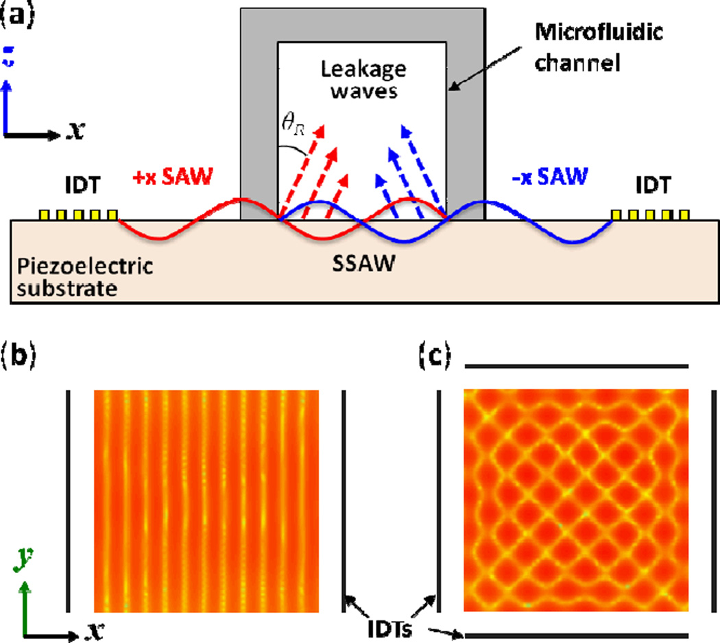
The basic principles that govern the interference of all waves give rise to the formation of SSAWs. If a pair of identical IDTs fabricated on a piezoelectric material generates two travelling SAWs propagating toward each other, the SAWs’ interference will result in a one-dimensional SSAW field as shown in Fig. 15a. Computational analysis of a one-dimensional SSAW on the surface of a substrate has led to the simulated interference pattern shown in Fig. 15b. The light and dark regions represent weak and strong amplitudes of the sound pressure field, respectively. The lightest and darkest lines show that SSAWs have a series of nodes (minimum field) and anti-nodes (maximum field) at fixed locations on the substrate surface. The distance between neighboring nodes—and also the distance between neighboring anti-nodes—is always half of the SAW wavelength on the substrate. BAW-based approaches typically use acoustically reflective materials in channel walls to form standing waves within the channel (or cavity). In contrast, the SSAW-based approaches create standing waves through direct interference of two or more identical SAWs and do not require channel walls to be made of acoustically reflective materials.
Fig. 15.
(a) A cross-section schematic of a microfluidic channel and the two IDTs used to generate travelling SAWs that propagate in opposite directions, establishing a SSAW across the channel width. This SSAW radiates acoustic leakage waves into the liquid at the Rayleigh angle. (b) and (c) show the simulated interference pattern of a one-dimensional and two-dimensional SSAW field on the substrate surface, respectively.
Similar to the one-dimensional case, a two-dimensional SSAW field can be formed on the surface of a substrate by generating SAWs from two pairs of IDTs arranged orthogonally, as shown in Fig. 15c. Note that the two-dimensional interference pattern is tilted 45 degrees with respect to the propagation direction of each SAW, and the shortest distance between nodes—and also the shortest distance between anti-nodes—in this two-dimensional patterned array is times the SAW wavelength on the substrate.
3.1.2 Primary acoustic radiation force
Both experiments and theory have established that when particles are immersed in a fluid medium, and a standing acoustic field is established in that fluid medium, the particles experience primary acoustic radiation forces that move them toward pressure nodes or pressure anti-nodes, depending on the material properties of both the particles and the surrounding fluid. The primary acoustic radiation force Fax is expressed as137
| (17) |
where p0 and Vp are the acoustic pressure and particle volume, respectively; λ and k are the wavelength and wavevector of the acoustic waves, respectively; β is compressibility; and ρ is density. φ, the acoustic contrast factor, indicates whether particles aggregate at pressure nodes (positive φ) or pressure anti-nodes (negative φ) and is given by:
| (18) |
where the subscripts p and f stand for particle and fluid, respectively. Most particles, such as polystyrene beads and blood cells, have a positive acoustic contrast factor φ, causing them to move toward the pressure nodes in a standing acoustic field.
SSAW-based microfluidic devices establish a standing acoustic field in fluid by means of IDT pairs forming a SSAW on a piezoelectric substrate in contact with the fluid (such as the setup in Fig. 15a). As discussed in Section 3.1.1, we have good understanding of the SSAW field present on the piezoelectric substrate. However, if we are to apply Eq. (17) in order to explain the working mechanism of SSAW-based microfluidic devices, we must understand the standing acoustic field present in the fluid (as induced by acoustic energy leakage from the contacting substrate).
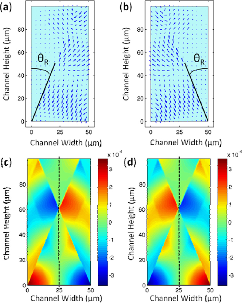
A recent study by the authors138 details a computational method used to model the SSAW-induced pressure field in the microfluidic channel depicted in Fig. 15a. The pressure gradient above the surface of the piezoelectric substrate leads to the generation of a longitudinal sound wave in the liquid. The displacement fields of the leakage wave created by two opposing travelling SAWs are plotted in Figs. 16a and 16b. Figs. 16c and 16d show the pressure fields corresponding to the combined displacement fields at two time snapshots with half a period time difference. During the time between the two snapshots, the amplitude of the pressure in the vertical center of the channel remains zero (indicated by the dashed line in Figs. 16c and 16d), while pressure in the other channel regions simply changes sign. These results indicate the existence of a standing acoustic pressure field in the fluid of the channel. Furthermore, the pressure nodal plane of this standing acoustic field sits immediately above the pressure node of the substrate SSAW that induced it. Several groups have experimentally confirmed the correspondence between pressure nodes of SSAW on the substrate and the acoustic field in the fluid.139–143 The authors’ computational model of the SSAW also demonstrated that the resulting primary acoustic radiation forces consist of axial mode (acting along the channel width) and transverse mode (acting along the channel height). The axial primary force is stronger than the transverse primary force. The partially reflected waves from the PDMS channel walls are included in the model to calculate the transverse primary force.
Fig. 16.
Time snapshots of displacement field of the longitudinal-mode leakage wave from a SAW propagating in (a) the positive x-direction and (b) the negative x-direction. The width of the channel is half the SAW wavelength and the height is one SAW wavelength. The pressure field resulting from the combined displacement fields (i.e. resulting from a SSAW on the substrate) is shown in the cross-section of the channel at (c) t = t0 and (d) t = t0 + τ/2. The dotted line denotes the pressure nodal plane in the middle of the channel. Reprinted with permission from ref. 138.
Eq. (17) indicates that particles suspended in fluid in which a standing acoustic field exists will be subjected to primary acoustic radiation forces that drive them to either the field’s nodes or anti-nodes. Because both theoretical and experimental work has demonstrated that the nodes and anti-nodes of the standing acoustic field in the fluid lie immediately above those of the substrate SSAW, microfluidic devices can be designed according to knowledge of the substrate SSAW. Recently, by using an acoustically reflective glass channel in a SAW device rather than an acoustically absorbent PDMS channel, Johansson et al. found that the glass-channel-based SAW system displayed features similar to those of BAW systems. Specifically, the size and shape of the channel significantly affected the acoustic field, and the node-to-node distance was half the sound wavelength in liquid.144
3.2 Microfluidic Technologies Enabled by SSAWs
Section 2.2 detailed the notable on-chip technologies and applications of TSAWs. These applications harnessed the acoustic streaming induced by the TSAWs to perform useful functions like fluid mixing and cell sorting. In this section, we review the latest on-chip innovations enabled by SSAWs. Instead of harnessing the acoustic streaming, SSAW-based devices use the primary acoustic radiation forces acting on particles via the surrounding fluid. We will detail devices that use these primary acoustic radiation forces to (1) focus a flow stream of particles into a single-file line, (2) separate a flow stream of particles based on particle properties, (3) actuate a single particle/cell moving with a flow stream, (4) pattern a group of particles in stagnant fluid, (5) manipulate a single particle/cell/organism in stagnant fluid, (6) manipulate proteins, and (7) align micro/nano materials. These technologies enrich the flexibility and functionality of SSAW-based, on-chip particle manipulation and will prove essential in building next-generation lab-on-a-chip systems.
3.2.1 Focusing of particles in a flow stream
Microfluidic focusing of particles in a liquid flow stream has attracted attention mainly due to its direct applicability to on-chip flow cytometry.145–149 To detect particles via flow cytometry, the particles need to be lined up single-file so they can each pass individually through a detection point. Many microfluidic devices have achieved particle focusing hydrodynamically, using sheath flows to align a particle stream single-file in the middle of a microfluidic channel. However, these sheath flows add substantial bulk to the microfluidic chip, increasing chip complexity and size. Sheath flow also introduces additional shear stress to the cells, which could affect cell viability and other functions. Therefore, a number of researchers have been investigating particle focusing methods that eschew sheath flows. Some of the best methods have harnessed SSAWs.
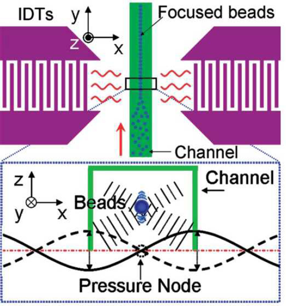
Shi et al. accomplished particle focusing in a microfluidic channel by situating the channel between two IDTs such that a SSAW was established across the channel width with a single pressure node that was located at the channel center.139 When particles passed through the region of SSAW exposure, the acoustic radiation force pushed them to the center of the microfluidic channel width (i.e., two-dimensional focusing), as shown in Fig. 17. Following this original work on SSAW-based particle focusing, Zeng et al. reported that adding Bragg reflectors inside or outside of the IDTs enhanced particle focusing effects.150 These SSAW-based, sheathless particle-focusing devices can be conveniently fabricated and operated.
Fig. 17.
Schematic and working mechanism of SSAW-based focusing of particles in a liquid flow stream. Reprinted with permission from ref. 139.
Though focusing of particles within the channel width satisfies the needs of some applications, others require that particles be focused in both the channel width and height (i.e., three-dimensional focusing). 3D focusing is especially important for flow cytrometry applications, as fixing particle position along the channel height minimizes fluorescence variations caused by varying focal depths. Shi et al. showed that SSAW can effectively achieve 3D focusing.138 Applying a SSAW to fluid in a microchannel, the researchers realized that a non-uniform acoustic field generates a primary acoustic radiation force transverse to the particles in the channel (i.e., in the z-direction, relative to the device plane). This force will direct all of the particles towards the point of maximum acoustic kinetic energy. However, the acoustic radiation force acting in the z-direction is weaker than that acting in the device plane. Therefore, particles focus first along the channel width and then migrate to a focal point along the channel height. The researchers used a prism placed adjacent to the microchannel to verify experimentally that particles did, in fact, focus in the z-direction; they then validated this with theoretical calculations.
3.2.2 Continuous separation of particles in a flow stream
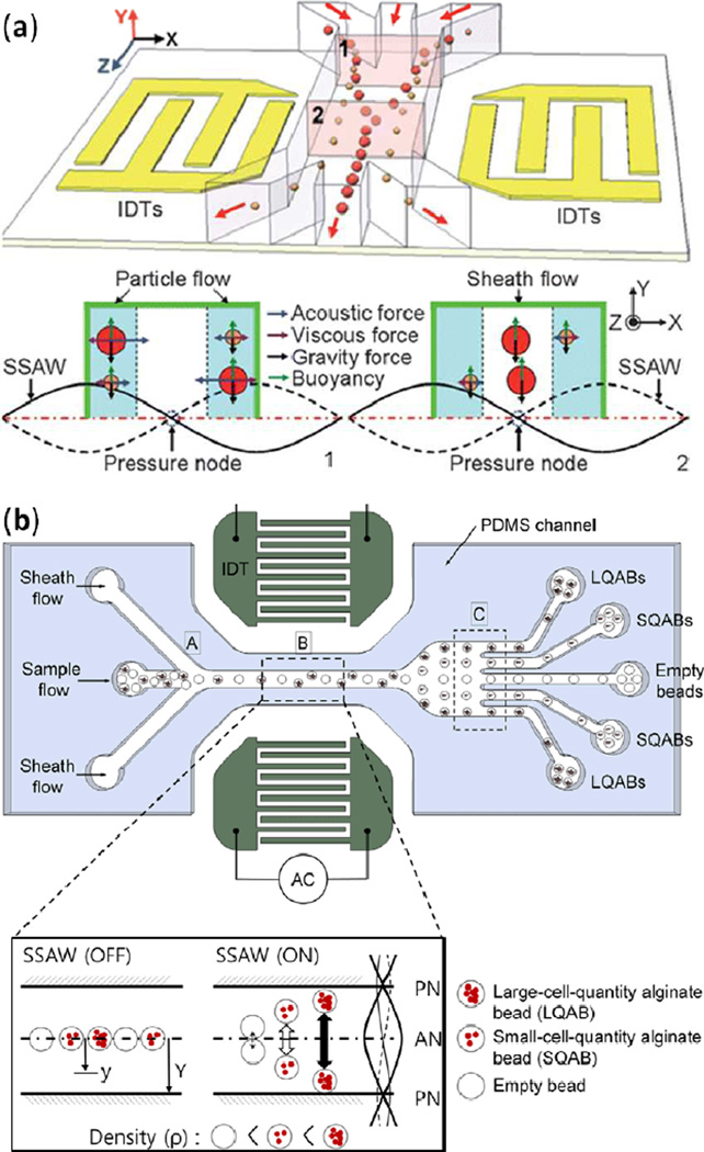
As implied by Eq. (17), a standing acoustic wave field exerts a primary acoustic radiation force whose magnitude and direction depend on particle size, density, and compressibility. Therefore, SSAW fields can differentiate particles or cells based on their physical properties. Shi et al. first reported SSAW-based continuous separation of particles in a flow stream in a PDMS microfluidic device.151 The researchers situated a microfluidic channel between two IDTs such that a SSAW was established across the channel width with half a wavelength spanning the channel and a single pressure node at the channel center. The researchers introduced a particle mixture into the channel from side inlets while simultaneously injecting a sheath flow from the center inlet (Fig. 18a). Because larger particles tend to experience larger primary acoustic radiation force, they migrate to the pressure node faster than smaller particles. Therefore, with appropriate length of the SSAW exposure region, SSAW enabled size-based particle separation. Larger particles move to the center outlet, while smaller particles remain in the side streams. This device demonstrated a simple, efficient, and cost-effective method for size-based particle separation.
Fig. 18.
(a) Schematic of device for SSAW-based separation of particles in a liquid flow stream, based on particle size. (b) Schematic of device for SSAW-based separation of cell-encapsulating polymer beads in a liquid flow stream, based on bead density. Reprinted with permission from refs 151 and 154.
Following the work of Shi et al., Nam et al. developed a similar device setup and applied it to sorting blood cells from platelets.152 First, to demonstrate the device, the researchers pumped a mixture of large and small particles through a separation channel from the device’s center inlet while introducing sheath flows from side inlets. By positioning SSAW pressure nodes near the channel walls, the researchers managed to move larger particles from the center stream towards the channel sides. Smaller particles could then be collected from a middle outlet, while larger particles were collected from side outlets.
Nam et al. then applied this device setup to blood samples in order to separate platelets from red and white blood cells.153 Because platelets are smaller than red and white blood cells, SSAW exposure in the separation channel resulted in large primary acoustic radiation forces pushing the red and white blood cells to the channel sides while platelets remained in the channel center. The SSAW-based sorting process effectively removed 99% of blood cells and achieved 74% separation efficiency for platelets. The work of Nam et al. demonstrated that SSAW not only effectively sorts particles, but also efficiently differentiates components of biological samples.
In addition to separating a particle flow stream based on particle size, SSAW devices can separate based on particle density. Cell-encompassing polymer beads provide one such example. There are numerous potential biological applications associated with encapsulating cells in biocompatible polymers. Although researchers have effectively generated monodispersive polymer beads, they often struggle when attempting to control the number of cells encased by each polymer bead. To circumvent this challenge, Nam et al. exploited the increased polymer bead density associated with multiple contained cells. As a particle stream of polymer beads was flowed through a channel, the researchers used a SSAW with pressure nodes at either channel wall to drive the more dense beads to the channel sides while the less dense beads remained in the channel center.154 In this device, large-cell-quantity alginate beads (LQABs), small-cell-quantity alginate beads (SQABs), and empty beads were collected from their respect outlets (Fig. 18b). The device attained 97% separation efficiency and 98% separation specificity for LQABs. This device demonstrated that SSAWs can be employed to effectively sort particles in a flow stream based on both size and density.
Supplementing the work of previous groups, Jo et al. reported a sheathless method to separate equally-sized polystyrene and melamine beads based on their density differential.155 To achieve sheathless separation, the researchers placed two pairs of IDTs side-by-side along a microfluidic channel. The first IDT pair generated a SSAW field with a pressure node in the channel center in order to focus the particle stream. After passing through the first IDT pair and being focused into a single-file line, the particle stream passed through the second IDT pair. The second IDT pair generated a SSAW field with pressure nodes at the channel walls, pushing the high-density melamine beads (1.71 g/cm3) to the channel sides while low-density polystyrene beads (1.05 g/cm3) remained in the center stream. The device achieved 89.4% separation efficiency at a 2 µL/min flow rate, demonstrating the ability of SSAW to focus and separate particles all in one integrated unit. Guldiken et al. also reported an integration of SSAW-based focusing and separation to achieve sheathless separation of particles in a flow stream.156
3.2.3 Actuating a single particle in a flow stream
The previous section described how SSAW could be used to continuously separate a flow stream of particles based on the particles’ physical properties (size and density). However, there are situations where it is desirable to sort a single particle moving in a liquid flow stream. A prime example is on-chip flow cytometry. After particles are focused and individually detected they are often sorted based on a property determined during detection (e.g., presence of a cell surface protein as determined by fluorescence). Several mechanisms have been proposed for on-chip particle/cell actuation including electrokinetic, magnetic, optical, and hydrodynamic forces.157–161 Recently, researchers have also proposed SSAW-based particle/cell actuation.162–168
While TSAW-based cell actuation (described in Section 2.2.5) utilizes acoustic streaming to move a cell, SSAW-based actuation moves the cell by means of primary acoustic radiation force. Because this primary acoustic radiation force pushes cells, particles, and droplets toward the SSAW pressure nodes (or anti-nodes, depending on their properties), these objects can be moved across the width of a microfluidic channel—and thereby sorted—by changing the position of a SSAW pressure node (or anti-node). By manipulating SSAW phase, researchers have demonstrated precise 1D actuation of micro-objects in continuous flow.162–164 Most recently, Ding et al. utilized SSAW-based actuation to construct a tunable device that precisely sorts single cells in a liquid flow stream into as many as five separate outlet channels (Fig. 19).165 In their work, the researchers positioned a microfluidic channel between two parallel chirped IDTs; these chirped IDTs operated in a wide frequency range, allowing them to generate a variety of SAW wavelengths. The width of the device channel was carefully selected so that only one pressure node could exist between the channel walls. The researchers tested their sorting device by pumping HL-60 cells through the channel. At frequency f1 (9.8 MHz), the primary acoustic radiation force pushed the cell towards the SSAW field pressure node positioned at the topmost outlet channel (Fig. 19a). Switching the input frequency to f5 (10.9 MHz) shifted the pressure node downward and guided the cell to the lowest outlet channel (Fig. 19b). Intermediate input frequencies f2, f3, and f4 were used to guide the cell to the intermediate outlet channels. Fig. 19c shows multichannel cell sorting, in which the device sorted cells contained in a liquid flow stream into five separate channels. This device demonstration shows the feasibility of SSAW-based actuation for the sorting of individual cells in on-chip flow cytometry. Li et al. recently applied the same principle to sort water-in-oil droplets into five separate outlets with a throughput of 222 droplets per seconds.166
Fig. 19.
Left panel shows the working mechanism of SSAW-based sorting of a single cell contained in a liquid flow stream. (a) At an input signal frequency f1 (9.8 MHz), the primary acoustic radiation force directs the cell to the pressure node at the upper wall of the channel, and the cell is collected from the topmost outlet. (b) At an input signal frequency f2 (10.9 MHz), the pressure node is shifted to the lower wall of the channel, and the cell is collected from the lowermost outlet. Right panel shows images of the experiment: HL-60 cells are driven individually to one of five desired outlet channels at five specific frequencies. Reprinted with permission from ref. 165.
3.2.4 Patterning a group of particles in stagnant fluid
Techniques that can noninvasively arrange particles or cells (contained in a stagnant fluid) into desired patterns are invaluable for many biomedical applications, including microarrays, tissue engineering, and regenerative medicine. The non-contact, non-invasive primary acoustic radiation forces generated by SSAWs serve as an excellent enabler of such particle/cell patterning techniques. Wood et al. exploited SSAWs to demonstrate the linear alignment of particles.142 Following this work, Shi et al. developed “acoustic tweezers” to effectively and non-invasively arrange particles and cells.141 The acoustic tweezers device consists of a PDMS microfluidic channel and a pair of IDTs deposited on a piezoelectric substrate in a parallel (Fig. 20a) or orthogonal (Fig. 20b) arrangement. After applying a RF signal to both IDTs to generate a SSAW field, particles/cells were patterned in parallel lines or arrays. Figs. 20c and 20d show the distribution of microbeads before and after the 1D and 2D patterning processes. Patterning of massive particles in a large area has also been demonstrated using a similar mechanism and similar devices.167
Fig. 20.
SSAW-based patterning of a group of particles in stagnant fluid. Schematic of (a) 1D patterning using two parallel IDTs, (b) 2D patterning using two orthogonal IDTs (the angle between the IDTs can be changed to achieve different patterns). (c) Distribution of fluorescent microbeads before and after the 1D (SAW wavelength was 100 um) patterning process, (d) and the 2D patterning process (SAW wavelength was 200 um). Reprinted with permission from ref. 141.
The patterning of the aforementioned devices is static because the working frequency range of the SSAW is very narrow (the regular IDTs used in the devices have a bandwidth of ~0.2 MHz). In order to enable dynamic SSAW-based particle patterning, Ding et al. constructed a device with slanted-finger interdigital transducers (SFITs).41 By tuning the input signal frequency, both the frequency and originating location of the main SAW beam can be tuned, permitting dynamic control of the particle patterning. The authors demonstrate SFIT-produced SSAW-based patterning of HL-60 leukemia cells; the period of the two cell lines was tuned to 60 µm, 78 µm, and 150 µm, using input signal frequencies of 45, 36, and 27 MHz, respectively.
3.2.5 Manipulating a single particle/cell/organism in stagnant fluid
In the previous section, we described recent developments in SSAW-based patterning for large numbers of particles/cells in stagnant fluid, with important biomedicine-related applications in microarrays, tissue engineering, and regenerative medicine. In addition to moving multiple particles/cell into a patterned formation, non-invasive manipulation of a single particle or cell contained in stagnant fluid is also invaluable in many biomedical applications, such as the study of cell-to-cell communication and interaction. Currently, many biologists employ optical tweezers for single-cell manipulation due to their excellent precision and versatility.169 However, optical tweezers depend on complex and expensive optical setups, and the associated focused laser beam can heat the moved object to temperatures that cause physiological damage. To reduce costs and minimize damage, researchers have been developing SSAW-based single-cell manipulation platforms.
When a single particle contained in stagnant fluid is exposed to a SSAW field, the primary acoustic radiation force acts on the particle and pushes it to either a pressure node or antinode (depending on the particle’s properties), trapping it at that location. Once the particle has been trapped, it can be moved by changing the frequencies and phase of the constituent SAWs.162–168 Ding et al. recently demonstrated SSAW-based manipulation on particles, cells, and even millimeter-sized C. elegans worms contained in stagnant fluid inside a microfluidic chamber.29 Their device consisted of a 2.5×2.5 mm2 PDMS chamber asymmetrically bonded to a LiNbO3 substrate between two orthogonal pairs of chirped IDTs (Fig. 21a). The two pairs of chirped IDTs allowed the device to move the objects trapped in the pressure nodes in x and y directions independently. Fig. 21b displays the effectiveness of this technique, as the researchers manipulated a single bovine red blood cell through a pre-programmed pattern, taking a photograph at each cell position and compositing the images to trace the cell’s path. The researchers examined particle speed and potential for cell damage, finding that a 10 µm polystyrene bead is accelerated to a velocity as high as 1.6 mm/s, and that HeLa cells exhibited no significant physiological change after being exposed to high power acoustic fields for 10 min. Finally, the researchers placed C. elegans worms inside the chamber to show that they could move an entire organism without damage, as shown in Fig 21c.
Fig. 21.
(a) Device schematic and working mechanism of SSAW-based manipulation of a single particle contained in stagnant fluid (i.e., acoustic tweezers). (b) Composited image of a single bovine red blood cell translated in two dimensions by changing the frequencies of the constituent SAWs. (c) Optical images showing the manipulation and stretching of a whole C. elegans worm. Reprinted with permission from ref. 29.
The acoustic tweezers device described above is biocompatible, versatile, low-cost, simple in design, and convenient to operate, making it an extremely attractive alternative to conventional optical tweezers for manipulation of single particles or cells. The successful trapping and manipulation of a whole organism also sets the device apart.
3.2.6 Protein manipulation
Supported lipid bilayers (SLBs) are critically important in cellular biology, as they regulate the intracellular and intercellular movement of ions, proteins, and other molecules.170 Recently, researchers have applied SSAWs to pattern SLBs, for use in membrane biology study. Hennig et al. showed that local concentrations of SLBs can be modulated by applying SSAW to a substrate.171 In the experiment, standard IDTs generated shear SSAWs on a LiTaO3 substrate to induce lateral reorganization of a lipid bilayer. Higher membrane density was found in the antinodes of the in-plane shear SSAW, while lower membrane density was found in the nodes. The researchers carefully monitored pattern formation and decay by fluorescence microscopy in order to study diffusion times of supported bilayers during the process. Diffusion times matched those attained with conventional methods, confirming the accuracy of SSAW for patterning of SLBs. Hennig et al. further demonstrated the modulation of DNA density on supported lipid bilayers by binding DNA to a catonic SLB.172
Based on this lipid-patterning approach, Neumann et al. further demonstrated that proteins bound to SLBs can be accumulated, transported, and segregated using shear SSAWs.173 As shown in recent work, SSAW-induced membrane modulations can achieve accumulation of labeled lipids. When the lipids are labeled with biotin, a biotin-binding protein called neutravidin accumulates alongside the lipids at pressure antinodes. The authors finely controlled the movement of proteins on SLBs by adjusting the phase between the two SAWs that combine to form the SSAWs. Phase adjustments in turn changed the locations of pressure nodes and antinodes, enabling protein transport in the 2D plane of the substrate. Finally, the group used shear SSAWs to separate avidin and streptavidin (two different biotin-binding proteins) based on their sizes (Fig. 22a). Since streptavidin is the smaller of the two, it migrated towards the regions with high lipid bilayer densities at the antinodes. In contrast, SSAWs pushed the larger avidin proteins towards the pressure nodes, resulting in size-based protein segregation (Fig. 22b–c). Thus, SSAW-based microfluidic devices can be used to manipulate proteins on SLBs with operational simplicity and high success rate.
Fig. 22.
(a) Schematic of SSAW-based protein separation mechanism. A LiTaO3 chip with IDTs (153 MHz/wavelength 26.6 µm) on opposite sides is used to generate a shear SSAW. The supported membrane (~4 nm thick) and protein segregation of membrane-bound streptavidin (red, Texas Red label) and avidin (green, Atto 488 label) can be observed by fluorescence microscopy through the optically transparent chip. (b) Fluorescence images of dye-labelled avidin and streptavidin. (c) Overlay images to demonstrate the segregation of avidin and streptavidin. Reprinted with permission from ref. 173.
3.2.7 Microtube alignment
In addition to using TSAWs to reorientate micro/nano objects (see Section 2.2.6), researchers have also used SSAWs to align microtubes and nanowires.174,175 Kong et al.174 placed a droplet containing a suspension of rolled-up Cr microtubes on a LiNbO3 substrate between two parallel IDTs. When the IDTs were energized and a SSAW was established in the substrate beneath the Cr microtube suspension, the microtubes uniformly aligned parallel to the propagation direction of the SAWs (Fig. 23). In the SSAW field, these Cr tubes connected together end-to-end, forming tube bridges in a relatively high concentration.
Fig. 23.
(a) Suspension of rolled-up Cr microtubes placed on a LiNbO3 substrate between two parallel IDTs. IDTs are energized to establish a SSAW in the substrate, and the associated electric field uniformly aligned the microtubes parallel to the SAW propagation direction. (b) Optical image of aligned tube chain obtained from 30 µm long Cr tubes confined within the fluidic channel, after application of SAWs (30 MHz, 13 dBm). Reprinted with permission from ref. 174.
To ascertain the physics underlying the alignment process, the researchers conducted control experiments with two sets of rolled-up microtubes, both conductive (Cr) and non-conductive (SiO/SiO2), and two different piezoelectric surfaces, LiNbO3 with a thin metal cover (to isolate the microtubes from the electric field at the substrate surface) and uncovered LiNbO3 (exposing the microtubes to the electric field at the substrate surface). Experiment results showed that the Cr microtubes did not align on the metal-covered LiNbO3 substrate, but did align on the uncovered LiNbO3 substrate. Furthermore, the SSAW exerted little influence on the non-conductive microtubes regardless of substrate. This proved that it was the electric field associated with the SSAW, not the acoustic field, that was responsible for the alignment of the rolled-up metal microtubes.
4. Conclusions and Perspectives
As summarized in this article, SAWs have demonstrated tremendous capability in microfluidic applications. TSAWs and SSAWs have, collectively, been used to achieve: rapid and localized fluid mixing, droplet translation, fluid pumping in microchannels, droplet-based rotational micromotors, droplet jetting and atomization, reorientation of nano-objects, as well as particle/cell focusing, sorting, manipulation, and patterning. Some of these functions have been achieved in microfluidics using techniques other than SAW as well. However, SAW has a combination of advantages that competing techniques lack: simple fabrication, high biocompatibility, versatility, compact and inexpensive devices and accessories, fast fluid actuation, contact-free particle manipulation, and compatibility with other microfluidic components. In addition, using SAW microfluidics, one can achieve functions that are unattainable by conventional methods. For example, non-invasive cell manipulation can be performed in a native cell environment, permitting normal cell growth and proliferation subsequent to the manipulation. This would have significant benefits in the study of stem cell differentiation, cell-cell communication, and tissue engineering. We believe that these unique advantages and functions position SAW to be a key component in the use of microfluidics as a tool in medical diagnostics and biological/chemical studies. For this to happen—for SAW microfluidic technologies to progress from research labs to everyday use in real-world applications—a number of hurdles must be overcome. In this section, we identify some of the areas requiring progress from both theorists and technical innovators.
The physics of SAW microfluidics, whether harnessing TSAW or SSAW, encompasses a range of phenomena, including acoustic radiation forces, acoustic streaming, jetting, and atomization. Theoretical work over the last two decades has fleshed out our understanding of this wide-ranging physics. However, work remains to be done if our theoretical understanding is to be complete. For instance, in the case of SAW-induced fluid atomization, there is an order of magnitude difference between the driving SAW frequency and the droplet excitation frequency (leading to atomization). This massive difference between driving and response frequencies remains poorly understood. Similarly, numerical simulations (e.g., computational fluid dynamics modeling) of SAW-induced acoustic streaming have been hampered by the large discrepancy in the time and space domains between the driving SAW and the resulting liquid streaming. More specifically, a very small time step and a very fine mesh are required to capture the SAW actuation of the liquid, but the resulting streaming occurs over a relatively large time scale and large spatial dimensions. Additionally, quantitative estimates of primary acoustic radiation force acting on complexly-shaped biological particles are currently inadequate, impeding the understanding and optimization of SSAW-based microfluidic platforms. Advancements in SAW-based microfluidic devices—and their adoption in real-world applications—will be strongly facilitated by SAW researchers improving the theoretical foundations of the discipline.
While the theorists do their part, there is much room for continued device innovations. As described throughout this article, much of SAW microfluidics to date has relied on either acoustic streaming or primary acoustic radiation forces to accomplish useful actions. These two phenomena occur simultaneously for both TSAW and SSAW, but for any given device application, the influence of one effect relative to the other is dictated by factors such as particle size, SAW type, SAW power, SAW frequency, and channel geometry.176 For particle manipulation techniques that rely on SSAW, primary acoustic radiation forces are the enabler, and acoustic streaming is considered an undesirable concurrence that disrupts otherwise predictable particle movements. To improve the precision of SSAW-based particle manipulation, it would be beneficial for researchers to find ways to minimize acoustic. It should be pointed out that little research has been done on the acoustic streaming induced by SSAW. This is an area in need of attention; perhaps through some clever innovations, researchers may even be able to convert SSAW-induced acoustic streaming from a complicating factor to an enabling mechanism.
Further improvements to the exactness of SSAW-based particle manipulation are also needed. Current acoustic tweezers devices have micrometer-scale resolution. Their resolution could potentially be refined to the nanometer-scale by using high-frequency SAWs. However, increasing SAW frequency results in higher energy attenuation as the acoustic wave transfers from the substrate surface to the contacting fluid. High SAW frequencies also result in stronger acoustic streaming, which compounds the increasing effect of streaming on particle movement as the particle size decreases. Both the increased energy attenuation and augmented acoustic streaming will need to be addressed in order to improve the resolution, and thus the applicability, of SSAW-based particle manipulation.
In addition to the issue of manipulation resolution, researchers have struggled to achieve precise control of particle manipulation in the device out-of-plane (z) direction. Applications such as tissue engineering and cell-cell communications rely on careful control of cells in all three dimensions. For SSAW-based methods to become an all-around particle/cell manipulation solution, researchers will need to gain precise control of the z direction.
Other device innovations may come from use of new piezoelectric substrates. Among hundreds of piezoelectric materials, LiNbO3 has found ubiquitous use in SAW microfluidics due to its transparency, which enables easy microscope observation of on-chip events. More effort could be applied to exploring the potential benefits of other substrate materials. For example, the use of phononic crystals could help better manipulate SAW propagation and amplitude, and the use of piezoelectric thin films may lead to reduced device cost. In addition to considering new piezoelectric substrate materials, researchers should expand an existing trend: the use of disposable superstrates. These superstrates, which are bonded to the microfluidic components of the overall device, are acoustically coupled to the substrate via a liquid layer.177,178 Such superstrates serve to separate the expensive piezoelectric substrate and its IDTs from the microfluidic components, making a single SAW-based device reusable by exchanging the superstrates. For example, if a cell patterning and culturing microfluidic device existed on a superstrate, multiple patterned superstrate cultures could be obtained with a single piezoelectric substrate. In combination with investigation of new substrate/superstrate materials, alternate acoustic modes, such as transverse SAW or plate waves, may also offer opportunity for new innovations.
SAW-based microfluidics has come a long way in the past decade. It has been used to successfully perform a wide range of biomedicine-oriented lab functions, from cell focusing, cell sorting, cell manipulation, cell enrichment, cell lysis, to on-chip PCR, biosensing, and many more. In fact, these functions span the full spectrum of laboratory functions, from sample preparation all the way to final analysis; in other words, SAWs have been used to, on the aggregate, create a lab-on-a-chip. Researchers should now focus on actually creating that lab-on-a-chip. This will require integrating multiple SAW techniques onto a single microfluidic device, with transitions from one stage to another.
In order to make this adoption of SAW-based microfluidics a reality, researchers must build integrated devices capable of performing a complete conventional laboratory process, from start to finish. In this regard, facilitating the application of SAW-based microfluidics to real-world laboratory functions will take more than integrating multiple SAW techniques onto a coordinated device. It will also require creative solutions to a classic problem of microfluidic devices: the mismatch between coin-sized microchips and the large peripheral control and detection systems that still reside off-chip. Researchers will need to integrate function generators, amplifiers, SAW transducers, and signal processors onto a compact system. This integration and miniaturization is doable (SAW devices and accessories have already been integrated into compact, low-cost electronic devices such as cell phones), and it is necessary if SAW-based microfluidic devices are to be adopted for use in biological studies and medical diagnostics that researchers have long predicted.
Acknowledgements
This research was supported by National Institutes of Health (1DP2OD007209-01) and the Penn State Center for Nanoscale Science (MRSEC) under grant DMR-0820404.
Notes and references
- 1.Whitesides GM. Nature. 2006;442:368–373. doi: 10.1038/nature05058. [DOI] [PubMed] [Google Scholar]
- 2.Neuzil P, Giselbrecht S, Länge K, Huang TJ, Manz A. Nat. Rev. Drug Discov. 2012;11:620–632. doi: 10.1038/nrd3799. [DOI] [PMC free article] [PubMed] [Google Scholar]
- 3.Mao X, Huang TJ. Lab Chip. 2012;12:1412–1416. doi: 10.1039/c2lc90022j. [DOI] [PMC free article] [PubMed] [Google Scholar]
- 4.Kovarik ML, Ornoff DM, Melvin AT, Dobes NC, Wang Y, Dickinson AJ, Gach PC, Shah PK, Allbritton NL. Anal. Chem. 2013;85:451–472. doi: 10.1021/ac3031543. [DOI] [PMC free article] [PubMed] [Google Scholar]
- 5.Squires TM, Quake SR. Rev. Mod. Phys. 2005;77:977–1026. [Google Scholar]
- 6.Manz A, Graber N, Widmer HM. Sens. Actuators, B Chem. 1990;1:244–248. [Google Scholar]
- 7.Arora A, Simone G, Salieb-Beugelaar G, Kim JT, Manz A. Anal. Chem. 2010;82:4830–4847. doi: 10.1021/ac100969k. [DOI] [PubMed] [Google Scholar]
- 8.Dittrich PS, Manz A. Nat. Rev. Drug Discov. 2006;5:210–218. doi: 10.1038/nrd1985. [DOI] [PubMed] [Google Scholar]
- 9.Beebe DJ, Mensing GA, Walker GM. Annu. Rev. Biomed. Eng. 2002;4:261–286. doi: 10.1146/annurev.bioeng.4.112601.125916. [DOI] [PubMed] [Google Scholar]
- 10.Wheeler AR. Science. 2008;322:539–540. doi: 10.1126/science.1165719. [DOI] [PubMed] [Google Scholar]
- 11.Eydelnant IA, Uddayasankar U, Li B, Liao MW, Wheeler AR. Lab Chip. 2012;12:750–757. doi: 10.1039/c2lc21004e. [DOI] [PubMed] [Google Scholar]
- 12.Tseng P, Judy JW, Carlo DD. Nat. Methods. 2012;9:1113–1119. doi: 10.1038/nmeth.2210. [DOI] [PMC free article] [PubMed] [Google Scholar]
- 13.Pamme N, Manz A. Anal. Chem. 2004;76:7250–7256. doi: 10.1021/ac049183o. [DOI] [PubMed] [Google Scholar]
- 14.Lenshof A, Laurell T. Chem. Soc. Rev. 2010;39:1203–1217. doi: 10.1039/b915999c. [DOI] [PubMed] [Google Scholar]
- 15.Monat C, Domachuk P, Eggleton BJ. Nat. Photon. 2007;1:106–114. [Google Scholar]
- 16.Mao X, Waldeisen JR, Juluri BK, Huang TJ. Lab Chip. 2007;7:1303–1308. doi: 10.1039/b708863a. [DOI] [PubMed] [Google Scholar]
- 17.Schmidt H, Hawkins AR. Nat. Photon. 2011;5:598–604. [Google Scholar]
- 18.Zhao Y, Stratton ZS, Guo F, Lapsley MI, Chan CY, Lin S-CS, Huang TJ. Lab Chip. 2013;13:17–24. doi: 10.1039/c2lc90127g. [DOI] [PMC free article] [PubMed] [Google Scholar]
- 19.Psaltis D, Quake SR, Yang C. Nature. 2006;442:381–386. doi: 10.1038/nature05060. [DOI] [PubMed] [Google Scholar]
- 20.Ruppel CCW, Reindl L, Weigel R. Microwave Magazine. 2002;3:65–71. [Google Scholar]
- 21.Polh A. IEEE Trans. Ultrason., Ferroelectr., Freq. Control. 2000;47:317–332. doi: 10.1109/58.827416. [DOI] [PubMed] [Google Scholar]
- 22.Gronewold TMa. Anal. Chim. acta. 2007;603:119–128. doi: 10.1016/j.aca.2007.09.056. [DOI] [PubMed] [Google Scholar]
- 23.Länge K, Blaess G, Voigt A, Götzen R, Rapp M. Biosens. Bioelectron. 2006;22:227–232. doi: 10.1016/j.bios.2005.12.026. [DOI] [PubMed] [Google Scholar]
- 24.Renaudin A, Chabot V, Grondin E, Aimez V, Charette PG. Lab Chip. 2010;10:111–115. doi: 10.1039/b911953a. [DOI] [PubMed] [Google Scholar]
- 25.Lee J, Choi Y-S, Lee Y, Lee HJ, Lee JN, Kim SK, Han KY, Cho EC, Park JC, Lee SS. Anal. Chem. 2011;83:8629–8635. doi: 10.1021/ac2020849. [DOI] [PubMed] [Google Scholar]
- 26.Lin S-CS, Mao X, Huang TJ. Lab Chip. 2012;12:2766–2770. doi: 10.1039/c2lc90076a. [DOI] [PMC free article] [PubMed] [Google Scholar]
- 27.Miller DL, Smith NB, Bailey MR, Czarnota GJ, Hynynen K, Makin IRS. J. Ultrasound Med. 2012;31:623–634. doi: 10.7863/jum.2012.31.4.623. [DOI] [PMC free article] [PubMed] [Google Scholar]
- 28.Wiklund M. Lab Chip. 2012;12:2018–2028. doi: 10.1039/c2lc40201g. [DOI] [PubMed] [Google Scholar]
- 29.Ding X, Lin S-CS, Kiraly B, Yue H, Li S, Chiang IK, Shi J, Benkovic SJ, Huang TJ. Proc. Natl. Acad. Sci. U.S.A. 2012;109:11105–11109. doi: 10.1073/pnas.1209288109. [DOI] [PMC free article] [PubMed] [Google Scholar]
- 30.Li H, Friend J, Yeo L, Dasvarma A, Traianedes K. Biomicrofluidics. 2009;3:34102. doi: 10.1063/1.3194282. [DOI] [PMC free article] [PubMed] [Google Scholar]
- 31.Friend J, Yeo LY. Rev. Mod. Phys. 2011;83:647–704. [Google Scholar]
- 32.Yeo LY, Friend JR. Biomicrofluidics. 2009;3 doi: 10.1063/1.3056040. 012002. [DOI] [PMC free article] [PubMed] [Google Scholar]
- 33.Bruus H, Dual J, Hawkes J, Hill M, Laurell T, Nilsson J, Radel S, Sadhal S, Wiklund M. Lab Chip. 2011;11:3579–3580. doi: 10.1039/c1lc90058g. [DOI] [PubMed] [Google Scholar]
- 34.Wixforth A. J. Lab. Automat. 2006;11:399–405. [Google Scholar]
- 35.Beyssen D, Le Brizoual L, Elmazria O, Alnot P. Sens. Actuators, B Chem. 2006;118:380–385. [Google Scholar]
- 36.Zhang G, Li Y. Micronanoelec. Tech. 2009;9 010. [Google Scholar]
- 37.Wang Z, Zhe J. Lab Chip. 2011;11:1280–1285. doi: 10.1039/c0lc00527d. [DOI] [PubMed] [Google Scholar]
- 38.Gedge M, Hill M. Lab Chip. 2012;12:2998–3007. doi: 10.1039/c2lc40565b. [DOI] [PubMed] [Google Scholar]
- 39.Fu YQ, Luo JK, Du XY, Flewitt AJ, Li Y, Markx GH, Walton AJ, Milne WI. Sens. Actuators, B Chem. 2010;143:606–619. [Google Scholar]
- 40.Tan MK, Friend JR, Yeo LY. Appl. Phys. Lett. 2007;91:224101. [Google Scholar]
- 41.Ding X, Shi J, Lin S-CS, Yazdi S, Kiraly B, Huang TJ. Lab Chip. 2012;12:2491–2497. doi: 10.1039/c2lc21021e. [DOI] [PMC free article] [PubMed] [Google Scholar]
- 42.Hashimoto K, Yamaguchi M. IEEE Trans. Ultrason. Ferroelectr. Freq. Control. 2001;48:1181–1188. doi: 10.1109/58.949731. [DOI] [PubMed] [Google Scholar]
- 43.Schröder CT, Scott WR., Jr J. Acoust. Soc. Am. 2001;110:2867–2877. [Google Scholar]
- 44.Adler E. IEEE Trans. Ultrason., Ferroelectr., Freq. Control. 1994;41:876–882. doi: 10.1109/58.330269. [DOI] [PubMed] [Google Scholar]
- 45.Auld B. Acoustic Fields and Waves in Solids. New York: Wiley Press; 1973. [Google Scholar]
- 46.Köster D. SIAM J. Sci. Comput. 2007;29:2352–2380. [Google Scholar]
- 47.Meng L, Cai F, Jin Q, Niu L, Jiang C, Wang Z, Wu J, Zheng H. Sens. Actuators, B Chem. 2011;160:1599–1605. [Google Scholar]
- 48.Wiklund M, Green R, Ohlin M. Lab Chip. 2012;12:2438–2451. doi: 10.1039/c2lc40203c. [DOI] [PubMed] [Google Scholar]
- 49.Wixforth A, Strobl C, Gauer C, Toegl A, Scriba J, Guttenberg ZV. Anal. Bioanal. Chem. 2004;379:982–991. doi: 10.1007/s00216-004-2693-z. [DOI] [PubMed] [Google Scholar]
- 50.Zeng Q, Guo F, Yao L, Zhu HW, Zheng L, Guo ZX, Liu W, Chen Y, Guo SS, Zhao XZ. Sens. Actuators B Chem. 2011;160:1552–1556. [Google Scholar]
- 51.Vanneste J, Buhler O. Proc. R. Soc. London, Ser. A Phys. 2010;467:1779–1800. [Google Scholar]
- 52.Alghane M, Chen BX, Fu YQ, Li Y, Luo JK, Walton AJ. J. Micromech. Microeng. 2011;21 015005. [Google Scholar]
- 53.Du XY, Fu YQ, Luo JK, Flewitt AJ, Milne WI. J. Appl. Phys. 2009;105 024508. [Google Scholar]
- 54.Tseng W-K, Lin J-L, Sung W-C, Chen S-H, Lee G-B. J. Micromech. Microeng. 2006;16:539–548. [Google Scholar]
- 55.Frommelt T, Gogel D, Kostur M, Talkner P, Hänggi P, Wixforth A. IEEE Trans. Ultrason., Ferroelectr., Freq. Control. 2008;55:2298–2305. doi: 10.1109/TUFFC.928. [DOI] [PubMed] [Google Scholar]
- 56.Shilton R, Tan MK, Yeo LY, Friend JR. J. Appl. Phys. 2008;104 014910. [Google Scholar]
- 57.Köster D. PhD Thesis. Augsburg University; 2006. [Google Scholar]
- 58.Nyborg WL. In: Acoustic Streaming. Mason WP, Thurston RN, editors. Vol. 11. New York: Academic Press; 1965. pp. 265–329. [Google Scholar]
- 59.Sadhal SS. Lab Chip. 2012;12:2292–2300. doi: 10.1039/c2lc40202e. [DOI] [PubMed] [Google Scholar]
- 60.Bradley C. J. Acoust. Soc. Am. 1996;100:1399–1408. [Google Scholar]
- 61.Bruus H. Lab Chip. 2012;12:20–28. doi: 10.1039/c1lc20770a. [DOI] [PubMed] [Google Scholar]
- 62.Zarembo L. Acoustic Streaming. Pt. III. New York: Plenum Press; 1971. pp. 138–199. [Google Scholar]
- 63.Doinikov AA. J. Fluid Mech. 1994;267:1–21. [Google Scholar]
- 64.Costanzo F, Gray GL, Andia PC. Int.J. Eng. Sci. 2005;43(7):533–555. [Google Scholar]
- 65.Andia PC, Costanzo F, Gray GL. Int. J. Solids Struct. 2005;42:6409–6432. [Google Scholar]
- 66.King LV. Proc. R. Soc. London, Ser. A. 1934;147:212–240. [Google Scholar]
- 67.Yosioka K, Kawasima Y. Acustica. 1955;5:167–173. [Google Scholar]
- 68.Gorkov LP. Sov. Phys. Dokl. 1962;6:773–775. [Google Scholar]
- 69.Dual J, Hahn P, Leibacher I, Moller D, Schwarz T, Wang J. Lab Chip. 2012;12:4010–4021. doi: 10.1039/c2lc40733g. [DOI] [PubMed] [Google Scholar]
- 70.Bruus H. Lab Chip. 2012;12:1014–1021. doi: 10.1039/c2lc21068a. [DOI] [PubMed] [Google Scholar]
- 71.Evander M, Nilsson J. Lab Chip. 2012;12:4667–4676. doi: 10.1039/c2lc40999b. [DOI] [PubMed] [Google Scholar]
- 72.Barnkob R, Augustsson P, Laurell T, Bruus H. Phys. Rev. E. 2012;86 doi: 10.1103/PhysRevE.86.056307. 056307. [DOI] [PubMed] [Google Scholar]
- 73.Frommelt T, Kostur M, Wenzel-Schäfer M, Talkner P, Hänggi P, Wixforth A. Phys. Rev. Lett. 2008;100 doi: 10.1103/PhysRevLett.100.034502. 034502. [DOI] [PubMed] [Google Scholar]
- 74.Luong T-D, Phan V-N, Nguyen N-T. Microfluid. Nanofluid. 2011;10:619–625. [Google Scholar]
- 75.Rezk AR, Qi A, Friend JR, Li WH, Yeo LY. Lab Chip. 2012;12:773–779. doi: 10.1039/c2lc21065g. [DOI] [PubMed] [Google Scholar]
- 76.Renaudin A, Tabourier P, Zhang V, Camart JC, Druon C. Sens. Actuators, B Chem. 2006;113:389–397. [Google Scholar]
- 77.Franke TA, Wixforth A. ChemPhysChem. 2008;9:2140–2156. doi: 10.1002/cphc.200800349. [DOI] [PubMed] [Google Scholar]
- 78.Wixforth A. Superlattic Microst. 2003;33:389–396. [Google Scholar]
- 79.Guttenberg Z, Muller H, Habermüller H, Geisbauer A, Pipper J, Felbel J, Kielpinski M, Scriba J, Wixforth A. Lab Chip. 2005;5:308–317. doi: 10.1039/b412712a. [DOI] [PubMed] [Google Scholar]
- 80.Tan MK, Friend JR, Yeo LY. Lab Chip. 2007;7:618–625. doi: 10.1039/b618044b. [DOI] [PubMed] [Google Scholar]
- 81.Li H, Friend JR, Yeo LY. Biomaterials. 2007;28:4098–4104. doi: 10.1016/j.biomaterials.2007.06.005. [DOI] [PubMed] [Google Scholar]
- 82.Rezk AR, Manor O, Friend JR, Yeo LY. Nat. Commum. 2012;3:1167. doi: 10.1038/ncomms2168. [DOI] [PubMed] [Google Scholar]
- 83.Schmid L, Wixforth A, Weitz DA, Franke T. Microfluid. Nanofluid. 2011;12:229–235. [Google Scholar]
- 84.Schneider SW, Nuschele S, Wixforth a, Gorzelanny C, Alexander-Katz a, Netz RR, Schneider MF. Proc. Natl. Acad. Sci. U.S.A. 2007;104:7899–7903. doi: 10.1073/pnas.0608422104. [DOI] [PMC free article] [PubMed] [Google Scholar]
- 85.Masini L, Cecchini M, Girardo S, Cingolani R, Pisignano D, Beltram F. Lab Chip. 2010;10:1997–2000. doi: 10.1039/c000490a. [DOI] [PubMed] [Google Scholar]
- 86.Cecchini M, Girardo S, Pisignano D, Cingolani R, Beltram F. Appl. Phys. Lett. 2008;92:104103. [Google Scholar]
- 87.Girardo S, Cecchini M, Beltram F, Cingolani R, Pisignano D. Lab Chip. 2008;8:1557–1563. doi: 10.1039/b803967d. [DOI] [PubMed] [Google Scholar]
- 88.Fallah MA, Myles VM, Krüger T, Sritharan K, Wixforth A, Varnik F, Schneider SW, Schneider MF. Biomicrofluidics. 2010;4:1–10. doi: 10.1063/1.3396449. [DOI] [PMC free article] [PubMed] [Google Scholar]
- 89.Fillafer C, Ratzinger G, Neumann J, Guttenberg Z, Dissauer S, Lichtscheidl IK, Wirth M, Gabor F, Schneider MF. Lab Chip. 2009;9:2782–2788. doi: 10.1039/b906006e. [DOI] [PubMed] [Google Scholar]
- 90.Shilton RJ, Glass NR, Chan P, Yeo LY, Friend JR. Appl. Phys. Lett. 2011;98:254103. [Google Scholar]
- 91.Shilton RJ, Langelier SM, Friend JR, Yeo LY. Appl. Phys. Lett. 2012;100 033503. [Google Scholar]
- 92.Glass NR, Shilton RJ, Chan P, Friend JR, Yeo LY. Small. 2012;8:1881–1888. doi: 10.1002/smll.201102282. [DOI] [PubMed] [Google Scholar]
- 93.Eggers J. Rev. Mod. Phys. 1997;69:865–929. [Google Scholar]
- 94.Calvert P. Chem. Mater. 2001;13:3299–3305. [Google Scholar]
- 95.de Gans B-J, Duineveld PC, Schubert US. Adv. Mater. 2004;16:203–213. [Google Scholar]
- 96.Tan MK, Friend JR, Yeo LY. Phys. Rev. Lett. 2009;103 doi: 10.1103/PhysRevLett.103.024501. 024501. [DOI] [PubMed] [Google Scholar]
- 97.Lefebvre A. Atomization and Sprays. New York: CRC Press; 1989. [Google Scholar]
- 98.Kurosawa M, Watanabe T, Futami A, Higuchi T. Sens. Actuators. A Phys. 1995;50:69–74. [Google Scholar]
- 99.Qi A, Yeo LY, Friend JR, Ho J. Lab Chip. 2010;10:470–476. doi: 10.1039/b915833b. [DOI] [PubMed] [Google Scholar]
- 100.Qi A, Friend JR, Yeo LY, Morton DAV, McIntosh MP, Spiccia L. Lab Chip. 2009;9:2184–2193. doi: 10.1039/b903575c. [DOI] [PubMed] [Google Scholar]
- 101.Heron SR, Wilson R, Shaffer SA, Goodlett DR, Cooper JM. Anal. Chem. 2010;82:3985–3989. doi: 10.1021/ac100372c. [DOI] [PMC free article] [PubMed] [Google Scholar]
- 102.Yoon SH, Huang Y, Edgar JS, Ting YS, Heron SR, Kao Y, Li Y, Masselon CD, Ernst RK, Goodlett DR. Anal. Chem. 2012;84:6530–6537. doi: 10.1021/ac300807p. [DOI] [PMC free article] [PubMed] [Google Scholar]
- 103.Qi A, Chan P, Ho J, Rajapaksa A, Friend J, Yeo LY. ACS Nano. 2011;5:9583–9591. doi: 10.1021/nn202833n. [DOI] [PubMed] [Google Scholar]
- 104.Ho J, Tan MK, Go D, Yeo LY, Friend J, Chang HC. Anal. Chem. 2011;83:3260–3266. doi: 10.1021/ac200380q. [DOI] [PubMed] [Google Scholar]
- 105.Alvarez M, Friend J, Yeo LY. Nanotechnology. 2008;19:455103. doi: 10.1088/0957-4484/19/45/455103. [DOI] [PubMed] [Google Scholar]
- 106.Friend JR, Yeo LY, Arifin DR, Mechler A. Nanotechnology. 2008;19:145301. doi: 10.1088/0957-4484/19/14/145301. [DOI] [PubMed] [Google Scholar]
- 107.Abramov OV. High-Intensity Ultrasonics. Amsterdam: Gordon and Breach Science Publishers; 1998. [Google Scholar]
- 108.Dong L, Chaudhury A, Chaudhury MK. Eur. Phys. J. E. 2006;21:231–242. doi: 10.1140/epje/i2006-10063-7. [DOI] [PubMed] [Google Scholar]
- 109.Tan MK, Friend JR, Mata OK, Yeo LY. Phys. Fluids. 2010;22:112112. [Google Scholar]
- 110.Collins DJ, Manor O, Winkler A, Schmidt H, Friend JR, Yeo LY. Phys. Rev. E. 2012;86 doi: 10.1103/PhysRevE.86.056312. 056312. [DOI] [PubMed] [Google Scholar]
- 111.Li H, Friend JR, Yeo LY. Biomed. Microdevices. 2007;9:647–656. doi: 10.1007/s10544-007-9058-2. [DOI] [PubMed] [Google Scholar]
- 112.Rogers PR, Friend JR, Yeo LY. Lab Chip. 2010;10:2979–2985. doi: 10.1039/c004822d. [DOI] [PubMed] [Google Scholar]
- 113.Tan MK, Friend JR, Yeo LY. Lab Chip. 2007;7:618–625. doi: 10.1039/b618044b. [DOI] [PubMed] [Google Scholar]
- 114.Franke T, Abate AR, Weitz DA, Wixforth A. Lab Chip. 2009;9:2625–2627. doi: 10.1039/b906819h. [DOI] [PubMed] [Google Scholar]
- 115.Franke T, Braunmüller S, Schmid L, Wixforth A, Weitz DA. Lab Chip. 2010;10:789–794. doi: 10.1039/b915522h. [DOI] [PubMed] [Google Scholar]
- 116.Schmid L, Franke T. Lab Chip. 2013 doi: 10.1039/c3lc41233d. [DOI] [PubMed] [Google Scholar]
- 117.Baughman RH, Zakhidov AA, de Heer WA. Science. 2002;297:787–792. doi: 10.1126/science.1060928. [DOI] [PubMed] [Google Scholar]
- 118.Strobl CJ, Schäflein C, Beierlein U, Ebbecke J, Wixforth A. Appl. Phys. Lett. 2004;85:1427–1429. [Google Scholar]
- 119.Smorodin T, Beierlein U, Ebbecke J, Wixforth A. Small. 2005;1:1188–1190. doi: 10.1002/smll.200500208. [DOI] [PubMed] [Google Scholar]
- 120.Seemann KM, Ebbecke J, Wixforth A. Nanotechnology. 2006;17:4529–4532. [Google Scholar]
- 121.Malanoski AP, Greanya VA, Weslowski BT, Spector MS, Selinger JV, Shashidhar R. Phys. Rev. E. 2004;69 doi: 10.1103/PhysRevE.69.021705. 021705. [DOI] [PubMed] [Google Scholar]
- 122.Liu YJ, Ding X, Lin S-CS, Shi J, Chiang I-K, Huang TJ. Adv. Mater. 2011;23:1656–1659. doi: 10.1002/adma.201003708. [DOI] [PubMed] [Google Scholar]
- 123.Liu YJ, Lu M, Ding X, Leong ESP, Lin S-CS, Shi J, Teng JH, Wang L, Bunning TJ, Huang TJ. J. Lab. Automat. 2012 doi: 10.1177/2211068212455632. [DOI] [PubMed] [Google Scholar]
- 124.Wu T-T, Huang Z-G, Lin S. Phys. Rev. B. 2004;69:1–10. [Google Scholar]
- 125.Lin S-CS, Huang T. Phys. Rev. B. 2011;83:174303. [Google Scholar]
- 126.Shi J, Lin S-CS, Huang TJ. Appl. Phys. Lett. 2008;92:111901. [Google Scholar]
- 127.Lin S-C, Huang T, Sun J-H, Wu T-T. Phys. Rev. B. 2009;79 094302. [Google Scholar]
- 128.Lin S-CS, Huang TJ. J. Appl. Phys. 2009;106 053529. [Google Scholar]
- 129.Lin S-CS, Tittmann BR, Sun J-H, Wu T-T, Huang TJ. J. Phys. D: Appl. Phys. 2009;42:185502. [Google Scholar]
- 130.Wu T-T, Chen Y-T, Sun J-H, Lin S-CS, Huang TJ. Appl. Phys. Lett. 2011;98:171911. [Google Scholar]
- 131.Lin S-CS, Tittmann BR, Huang Tony Jun. J. Appl. Phys. 2012;111:123510. doi: 10.1063/1.4729803. [DOI] [PMC free article] [PubMed] [Google Scholar]
- 132.Wilson R, Reboud J, Bourquin Y, Neale SL, Zhang Y, Cooper J. Lab Chip. 2010;11:323–328. doi: 10.1039/c0lc00234h. [DOI] [PubMed] [Google Scholar]
- 133.Bourquin Y, Reboud J, Wilson R, Zhang Y, Cooper JM. Lab Chip. 2011;11:2725–2730. doi: 10.1039/c1lc20320g. [DOI] [PubMed] [Google Scholar]
- 134.Reboud J, Bourquin Y, Wilson R, Pall GS, Jiwaji M, Pitt AR, Graham A, Waters AP, Cooper JM. Proc. Natl. Acad. Sci. U.S.A. 2012;109:15162–15167. doi: 10.1073/pnas.1206055109. [DOI] [PMC free article] [PubMed] [Google Scholar]
- 135.Bourquin Y, Wilson R, Zhang Y, Reboud J, Cooper JM. Adv. Mater. 2011;23:1458–1462. doi: 10.1002/adma.201004455. [DOI] [PubMed] [Google Scholar]
- 136.Reboud J, Wilson R, Zhang Y, Ismail MH, Bourquin Y, Cooper JM. Lab Chip. 2012;12:1268–1273. doi: 10.1039/c2lc20705b. [DOI] [PubMed] [Google Scholar]
- 137.Hartono D, Liu Y, Tan PL, Then XYS, Yung L-YL, Lim K-M. Lab Chip. 2011;11:4072–4080.. doi: 10.1039/c1lc20687g. [DOI] [PubMed] [Google Scholar]
- 138.Shi J, Yazdi S, Lin S-CS, Ding X, Chiang I-K, Sharp K, Huang TJ. Lab Chip. 2011;11:2319–2324. doi: 10.1039/c1lc20042a. [DOI] [PMC free article] [PubMed] [Google Scholar]
- 139.Shi J, Mao X, Ahmed D, Colletti A, Huang TJ. Lab Chip. 2008;8:221–223. doi: 10.1039/b716321e. [DOI] [PubMed] [Google Scholar]
- 140.Alvarez M, Friend JR, Yeo LY. Langmuir. 2008;24:10629–10632. doi: 10.1021/la802255b. [DOI] [PubMed] [Google Scholar]
- 141.Shi J, Ahmed D, Mao X, Lin S-CS, Lawit A, Huang TJ. Lab Chip. 2009;9:2890–2895. doi: 10.1039/b910595f. [DOI] [PubMed] [Google Scholar]
- 142.Wood CD, Evans SD, Cunningham JE, O’Rorke R, Wälti C, Davies AG. Appl. Phys. Lett. 2008;92 044104. [Google Scholar]
- 143.Johansson L, Enlund J, Johansson S, Katardjiev I, Yantchev V. Biomed. microdevices. 2012;14:1–11. doi: 10.1007/s10544-011-9606-7. [DOI] [PubMed] [Google Scholar]
- 144.Johansson L, Enlund J, Johansson S, Katardjiev I, Wiklund M, Yantchev V. J. Micromech. Microeng. 2012;22 025018. [Google Scholar]
- 145.Piyasena ME, Suthanthiraraj PPA, Applegate RW, Goumas AM, Woods TA, López GP, Graves SW. Anal. Chem. 2012;84:1831–1839. doi: 10.1021/ac200963n. [DOI] [PMC free article] [PubMed] [Google Scholar]
- 146.Mao X, Lin S-CS, Dong C, Huang TJ. Lab Chip. 2009;9:1583–1589. doi: 10.1039/b820138b. [DOI] [PubMed] [Google Scholar]
- 147.Mao X, Waldeisen JR, Huang TJ. Lab Chip. 2007;7:1260–1262. doi: 10.1039/b711155j. [DOI] [PubMed] [Google Scholar]
- 148.Mao X, Nawaz AA, Lin S-CS, Lapsley MI, Zhao Y, McCoy JP, El-Deiry WS, Huang TJ. Biomicrofluidics. 2012;6 doi: 10.1063/1.3701566. 024113. [DOI] [PMC free article] [PubMed] [Google Scholar]
- 149.Lapsley MI, Wang L, Huang TJ. Biomarkers Med. 2013;7:75–78. doi: 10.2217/bmm.12.103. [DOI] [PubMed] [Google Scholar]
- 150.Zeng Q, Chan HWL, Zhao XZ, Chen Y. Microelectron. Eng. 2010;87:1204–1206. [Google Scholar]
- 151.Shi J, Huang H, Stratton Z, Huang Y, Huang TJ. Lab Chip. 2009;9:3354–3359. doi: 10.1039/b915113c. [DOI] [PubMed] [Google Scholar]
- 152.Nam J, Lee Y, Shin S. Microfluid. Nanofluid. 2011;11:317–326. [Google Scholar]
- 153.Nam J, Lim H, Kim D, Shin S. Lab Chip. 2011;11:3361–3364. doi: 10.1039/c1lc20346k. [DOI] [PubMed] [Google Scholar]
- 154.Nam J, Lim H, Kim C, Kang JY, Shin S. Biomicrofluidics. 2012;6 doi: 10.1063/1.4718719. 024120. [DOI] [PMC free article] [PubMed] [Google Scholar]
- 155.Jo MC, Guldiken R. Sens. Actuators A Phys. 2012;187:22–28. [Google Scholar]
- 156.Guldiken R, Jo MC, Gallant N, Demirci U, Zhe J. Sensors. 2012;12:905–922. doi: 10.3390/s120100905. [DOI] [PMC free article] [PubMed] [Google Scholar]
- 157.Fu AY, Spence C, Scherer A, Arnold FH, Quake SR. Nat. biotechnol. 1999;17:1109–1111. doi: 10.1038/15095. [DOI] [PubMed] [Google Scholar]
- 158.Shen F, Hwang H, Hahn YK, Park J-K. Anal.Chem. 2012;84:3075–3081. doi: 10.1021/ac201505j. [DOI] [PubMed] [Google Scholar]
- 159.Mach AJ, Adeyiga OB, Carlo DD. Lab Chip. 2013;13:1011–1026. doi: 10.1039/c2lc41104k. [DOI] [PMC free article] [PubMed] [Google Scholar]
- 160.Wang MM, Tu E, Raymond DE, Yang JM, Zhang H, Hagen N, Dees B, Mercer EM, Forster AH, Kariv I, Marchand PJ, Butler WF. Nat. Biotechnol. 2005;23:83–87. doi: 10.1038/nbt1050. [DOI] [PubMed] [Google Scholar]
- 161.Carlo DD, Irimia D, Tompkins RG, Toner M. Proc. Natl. Acad. Sci. U.S.A. 2007;104:18892–18897. doi: 10.1073/pnas.0704958104. [DOI] [PMC free article] [PubMed] [Google Scholar]
- 162.O’Rorke RD, Wood CD, Walti C, Evans SD, Davies AG, Cunningham JE. J. Appl. Phys. 2012;111 094911. [Google Scholar]
- 163.Orloff ND, Dennis JR, Cecchini M, Schonbrun E, Rocas E, Wang Y, Novotny D, Simmonds RW, Moreland J, Takeuchi I, Booth JC. Biomicrofluidics. 2011;5 doi: 10.1063/1.3661129. 044107. [DOI] [PMC free article] [PubMed] [Google Scholar]
- 164.Meng L, Cai F, Zhang Z, Niu L, Jin Q, Yan F, Wu J, Wang Z, Zheng H. Biomicrofluidics. 2011;5 doi: 10.1063/1.3652872. 044104. [DOI] [PMC free article] [PubMed] [Google Scholar]
- 165.Ding X, Lin S-CS, Lapsley MI, Li S, Guo X, Chan CY, Chiang I-K, Wang L, McCoy JP, Huang TJ. Lab Chip. 2012;12:4228–4231. doi: 10.1039/c2lc40751e. [DOI] [PMC free article] [PubMed] [Google Scholar]
- 166.Li S, Ding X, Guo F, Chen Y, Lapsley MI, Lin S-CS, Wang L, McCoy JP, Cameron CE, Huang TJ. Anal. Chem. doi: 10.1021/ac400548d. [DOI] [PMC free article] [PubMed] [Google Scholar]
- 167.Wood CD, Cunningham JE, O’Rorke R, Wälti C, Linfield EH, Davies AG, Evans SD. Appl. Phys. Lett. 2009;94 054101. [Google Scholar]
- 168.Tran SBQ, Marmottant P, Thibault P. Appl. Phys. Lett. 2012;101:114103. [Google Scholar]
- 169.Grier DG. Nature. 2003;424:810–816. doi: 10.1038/nature01935. [DOI] [PubMed] [Google Scholar]
- 170.Richter RP, Bérat R, Brisson AR. Langmuir. 2006;22:3497–3505. doi: 10.1021/la052687c. [DOI] [PubMed] [Google Scholar]
- 171.Hennig M, Neumann J, Wixforth A, Radler JO, Schneider MF. Lab Chip. 2009;9:3050–3053. doi: 10.1039/b907157a. [DOI] [PubMed] [Google Scholar]
- 172.Hennig M, Wolff M, Neumann J, Wixforth A, Schneider MF, Radler JO. Langmuir. 2011;27:14721–14725. doi: 10.1021/la203413b. [DOI] [PubMed] [Google Scholar]
- 173.Neumann J, Hennig M, Wixforth A, Manus S, Radler JO, Schneider MF. Nano Lett. 2010;10:2903–2908. doi: 10.1021/nl100993r. [DOI] [PubMed] [Google Scholar]
- 174.Kong XH, Deneke C, Schmidt H, Thurmer DJ, Ji HX, Bauer M, Schmidt OG. Appl. Phys. Lett. 2010;96:134105. [Google Scholar]
- 175.Chen Y, Ding X, Lin S-CS, Yang S, Huang P-H, Nama N, Zhao Y, Nawaz AA, Guo F, Wang W, Gu Y, Mallouk TE, Huang TJ. ACS Nano. 2013;7:3306–3314. doi: 10.1021/nn4000034. [DOI] [PMC free article] [PubMed] [Google Scholar]
- 176.Li H, Friend J, Yeo L. Phys. Rev. Lett. 2008;101 doi: 10.1103/PhysRevLett.101.084502. 084502. [DOI] [PubMed] [Google Scholar]
- 177.Hodgson RP, Tan M, Yeo LY, Friend J. Appl. Phys. Lett. 2009;94 024102. [Google Scholar]
- 178.Langelier SM, Yeo LY, Friend J. Lab Chip. 2012;12:2970–2976. doi: 10.1039/c2lc40085e. [DOI] [PubMed] [Google Scholar]


