Abstract
Electrospinning is a high-throughput, low-cost technique for manufacturing long fibers from solution. Conventionally, this technique is used with covalent polymers with large molecular weights. We report here the electrospinning of functional peptide-based supramolecular polymers from water at very low concentrations (<4 wt %). Molecules with low molecular weights (<1 kDa) could be electrospun because they self-assembled into one-dimensional supramolecular polymers upon solvation and the critical parameters of viscosity, solution conductivity, and surface tension were optimized for this technique. The supramolecular structure of the electrospun fibers could ensure that certain residues, like bioepitopes, are displayed on the surface even after processing. This system provides an opportunity to electrospin bioactive supramolecular materials from water for biomedical applications.
Introduction
Electrospinning is an efficient, well-known process that produces nanometer-to-micrometer sized fibers with a tunable diameter.1−5 Nanofiber films produced by this technique provide a promising platform for biomaterials. This technique employs an electrified needle that ejects polymeric solutions toward a grounded collector. In the presence of a large electric field, the solution is drawn into a one-dimensional structure; moreover, the solvent evaporates as the electrified jet travels from the end of the needle toward the collector to produce a solid polymeric fiber. A major advantage of this high-throughput technique is the versatility: poly(ethylene glycol) (PEG),6 polycaprolactone (PCL),7,8 and collagen9 have all been electrospun. Additionally, these materials have been used as scaffolds for cells7 and surface coatings.5 Within certain parameters of viscosity, surface tension, and solution conductivity, additives like biological epitopes and proteins10 can be added to the electrospinning solution to produce bioactive fibers and matrices.
Electrospinning has been traditionally used to form fibers from high molecular weight polymers, but has recently been extended to supramolecular assemblies, such as surfactants,11,12 peptides,13 host–guest complexes,14 and cyclodextrin.15 In these cases, however, electrospinning small molecules requires high concentrations and organic solvents.12,15 Organic solvents can be undesirable in biomedical material processing because residual solvent is deleterious to cells and needs to be removed;16 additionally, nonaqueous solvents can denature proteins, reducing their bioactivity. Despite these challenges, supramolecular polymers provide numerous advantages: small molecules may be easier to synthesize reproducibly and the self-assembled structures can be morphologically well-defined. Furthermore, a myriad of structures can be generated as supramolecular polymers form fibers, tapes, and spherical micelles.17 Nonetheless, the ideal supramolecular system is a molecule that forms viscous solutions at low concentrations in aqueous media that can be formed into functional structures with minimal amounts of material. Ordered supramolecular polymers meet these criteria and can be rationally designed to form high aspect-ratio nanostructures with defined architecture. This defined architecture could ensure a strategic geometrical display of residues, such as bioactive signals on the surfaces of supramolecular polymers.
Peptide amphipiles (PAs) are a class of self-assembling biomolecules18−20 that have been extensively studied for a range of biomedical applications including spinal cord injury repair,21 wound healing,22 and enamel.23−29 These are versatile molecules that are processed in water to yield bioactive nanostructures that can guide cells through regenerative processes with bioactive cues. Combining the bioactivity of PAs with the versatility of electrospinning, which can be used to control the size, layering, and alignment1,30,31 of fibers, opens up the possibility of using electrospinning to coat medical devices in a controlled manner to improve their biointegration.
Materials and Methods
Materials
Peptide Amphiphiles
All resins and Fmoc-protected amino acids were purchased from Novabiochem Corporation. Solvents were purchased from Mallinckrodt (ACS reagent grade) and reagents were purchased from Aldrich and used as received. Solid-phase peptide synthesis was performed manually on a 0.5 mM scale using 50 mL peptide synthesis vessels (Chemglass) and a wrist-action shaker. A Wang resin with the first amino acid preloaded was used for all molecules. During synthesis, the Fmoc protecting group was removed by shaking the resin in 30% piperidine in N,N-dimethylformamide (DMF) for 10 min, rinsed, and repeated a second time. The resin was then washed with dichloromethane (DCM) and DMF and allowed to swell in DCM for 15 min before the coupling reaction. A total of 4 molar equiv of the Fmoc-protected amino acids were activated using 4 mol equiv of O-benzotriazole-N,N,N′,N′-tetramethyluronium-hexafluorophosphate (HBTU) and dissolved in 30 mL of DMF. A total of 6 molar equiv of N,N-diisopropylethylamine (DIEA) were added to the amino acid solution, which was allowed to sit for 2 min before being added to the resin. The coupling reaction went for 3 h, at the end of which, the resin was washed in DCM and DMF, and ninhydrin tests were done to check for the presence of free amines. After a positive ninhydrin result, the coupling was repeated. The palmitoyl tail was added using the ratio of palmitic acid/HBTU/DIEA of 4:4:6. PAs were cleaved by shaking the resin in a solution of 95% trifluoroacetic acid (TFA), 2.5% triisopropyl silane (TIS), and 2.5% H2O for 3 h. The solution was drained into a round-bottom flask and the resin was rinsed several times with DCM to remove all unbound peptide. The DCM and TFA were removed using rotary evaporation, and the PA residue was washed with cold diethyl ether and poured into a fritted filter. After several diethyl ether washes, the flakes were allowed to dry and then placed in a vacuum desiccator until HPLC purification.
After cleavage, ultrapure water was added to make the PA solution 20 mM and ammonia hydroxide was added until the pH was raised to 8. The solution was passed through a 0.22 μM filter and injected into a preparative-scale reverse-phase HPLC running a mobile phase gradient of 98% H2O and 2% acetonitrile (spectroscopic grade, Mallinckrodt) to 100% acetonitrile. The 0.1% NH4OH was added to all mobile phases to aid PA solubility. The Phenomenex C18 Gemini NX column had a 5 μm particle size, a 110 Å pore size, and was 150 × 30 mm. HPLC fractions were checked for the correct compound using electrospray ionization mass spectroscopy (ESI-MS). Rotary evaporation was used to remove acetonitrile and solutions were lyophilized (Labconco, FreezeZone6) at a pressure of 0.015 Torr. To remove any excess salts, PAs were dissolved in water and dialyzed in 500 molecular weight cutoff dialysis tubing (Spectrum Laboratories). After dialysis, the PAs were lyophilized.
Solutions of Peptide Amphiphiles
Solutions of peptide amphiphiles for characterization and electrospinning were made by solubilizing the amphiphiles in ultrapure water (Millipore filtered, resistivity 18.2 MΩ·cm). PAs 1 and 2 were dissolved in ultrapure water, bath sonicated for 25 min, and allowed to rest at room temperature for 15 min prior to use. PA solutions with concentrations up to 3 wt % dissolved readily; no heat treatment, additional surfactants, or salts were used during the course of this study.
Methods
Viscosity Measurements
Rheological properties of PA 1 and 2 were studied from 0.2 to 3 wt % (Figure 2). The shear rate-dependent viscosity data was collected with a Paar Physica Modular Compact Rheometer 300 operating in a parallel-plate configuration with a 25 mm diameter and 0.5 mm gap distance at 25 °C. The reported shear rate was the rate experienced by the fluid on the outer edge of the rotating plate.
Figure 2.
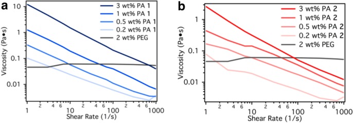
Shear rate and concentration dependent viscosity of (a) PA 1 and (b) PA 2 compared to 2 wt % aqueous PEG.
Measurements of Solution Conductivity
The solution conductivity was measured for PA 1 and 2 using a Malvern Zetasizer Nano (Figure 3b). We used approximately 300 μL of each solution.
Figure 3.
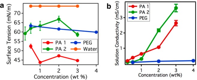
(a) Concentration-dependent surface tension measurements of PA 1 and 2. (b) Concentration-dependent solution conductivity measurements of PA 1 and PA 2. Error bars represent standard deviation.
Measurements of Surface Tension
The surface tension of PA 1 and PA 2 was measured with drop shape analysis using a KRÜSS DSA 100 instrument (Figure 3a). A droplet was measured from a 5 mL syringe and quantified within 5 s of forming the droplet.
Electrospinning
Electrospinning was performed using a horizontal polarized needle and collector. The needle and collector were spaced 5 cm apart. The voltage applied was 10 kV. The flow rate for all experiments, unless otherwise noted, were 0.04 mL/h. A syringe pump was used to eject material from an electrified needle. We used solutions of PA 1 and 2 with a 3 wt % concentration. Different substrates (e.g., stents, indium tin oxide, etc.) were taped with double-sided copper tape to the aluminum foil-based collector such that the electrospun fibers deposited on top.
Electron Microscopy
Scanning electron microscopy (SEM) was performed with a Hitachi S4800–II SEM. Electrospun samples were coated with 50 nm of osmium from an osmium tetroxide source using a Filgen Osmium Coater. This coating helped prevent charging of the sample inside the SEM.
Optical Imaging
Optical imaging was performed with a Nikon microscope in transmission mode. We used polarizers to perform polarized optical microscopy.
Results and Discussion
Characterization of PA 1 and 2
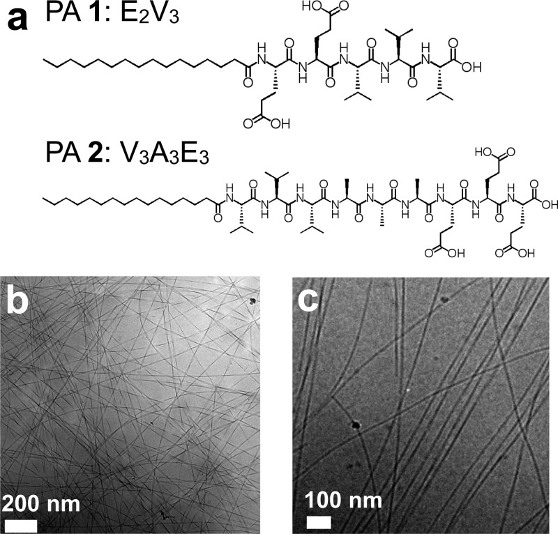
Studies were performed with two different PA molecules, C16-E2V3 (PA 1) and C16-V3A3E3 (PA 2) (Figure 1a). The latter has been shown to form highly viscous gels in solution and can be processed into aligned, monodomain arrays32 when drawn through a solution containing divalent cations. The amino acid valine has a high propensity for β-sheet hydrogen-bonding,33 which assists in the self-assembly of nanofibers, while charged glutamic acid residues impart solubility. Such noncovalent interactions are able to connect these small molecules into electrospun nanofibers in water.
Figure 1.
(a) Molecular structure of peptide amphiphiles 1 and 2. (b) Cryo-TEM image of PA 1 illustrating twisted ribbon morphology of nanostructures. (c) Cryo-TEM image of PA 2 illustrating fibrous morphology of nanostructures.
Peptide amphiphiles 1 and 2 were studied by cryogenic transmission electron microscopy (cryoTEM). Powders of peptide amphiphiles were dissolved in ultrapure water and bath sonicated per the procedure described in Methods. The preparation of samples for cryoTEM utilized dilute solutions with concentrations of <0.1% (w/v) in water. CryoTEM revealed that PA 1 formed a twisted, ribbon-like nanostructure with a width of 30 nm and a periodicity of 300 nm. The length of these structures was very long (>10 μm) as the start and end of a twisted ribbon could not be traced by the eye. We found that PA 2 assembled into cylindrical nanofibers. PA 2 formed long nanofibers with lengths exceeding 10 μm and widths of approximately 7 nm (Figure 1b,c). It was difficult to obtain cryo-TEM and conventional transmission electron microscopy images at higher concentrations used for electrospinning experiments (3 wt %) because the large number of nanofibers in solution rendered thick films that were no longer electron-transparent. It is important to note that this class of materials formed supramolecular polymers in water only; however, the related peptide lipid (PL) systems are soluble in organic solvents.
As shown by Figure 1, peptide amphiphiles assemble into one-dimensional structures in water. The one-dimensional supramolecular polymers are long and could become entangled with other strands thereby producing a more viscous solution. Past studies of these molecules found that the critical micelle concentration (CMC) of PAs tends to be very low. Electrospinning uniform fibers required the careful balance of mechanical properties, minimization of surface energy, and density of charges. To determine the appropriate concentration for electrospinning PAs, the viscosity, surface tension, and solution conductivity were measured.
Rheological Measurements of PA Solutions
Rheological properties of PA 1 and 2 were studied from low concentrations (0.2 wt %) up to 3 wt % in Milli-Q water (Figure 2). For comparison, we also measured the shear rate-dependent viscosity of aqueous solutions of 2 wt % 400 kDa poly(ethylene glycol) (PEG), a polymer commonly used for electrospinning. This concentration of PEG has been shown to have low viscosities that are still amenable for electrospinning; this control experiment allowed us to establish a threshold for the viscoelastic behavior for electrospinning PAs and other supramolecular polymers.3
The mechanical properties of the PA solutions demonstrated a dependence on concentration: the viscosity increased by more than an order of magnitude from 0.2 to 3 wt %, as seen in Figure 2. At low shear rates, both PA 1 and PA 2 (3 wt %) had similar viscosities of approximately 2 Pa·s and began to shear thin at higher shear rates. PA solutions proved to be more viscous than the PEG-based control at shear rates less than 100 Hz. In contrast, the PEG control had a viscosity that was nearly constant over the measurement range. High viscosities are required since high shear rates are applied to the solution at the tip of the electrospinning Taylor cone. Given this constraint, higher concentrations of these PAs (3 wt %) should be most suitable but are still 1 order of magnitude lower than other electrospun small molecules.
Surface Tension Measurements
In addition to a high viscosity, a solution with a minimal surface tension is preferred for electrospinning. A low surface tension implies that the surface energy of a solution can accommodate a larger surface area (e.g., cylindrical morphology) when the solution was ejected; this property can be manipulated by adding surfactants to the solution. Interestingly, the amphiphilic nature of the PA behaves like a surfactant and could help decrease the surface tension of the electrospinning solution. Therefore, a low surface tension enables long, uniform fibers that are free of “bead-on-string” morphologies.30
The surface tension of PA 1 was approximately 44.7 milliNewtons (mN) per meter (m) at 3 wt %. PA 2 had a higher surface tension of 58 mN/m at 3 wt %. The surface tension of PA solutions varied with concentration; however, there was no clear trend between concentration and surface tension. The surface tension of water measured with the same technique was 73.8 mN/m at room temperature. The surface tension of PAs was lower than that of water at all PA concentrations. Furthermore, both PA-based solutions had surface tensions comparable to or lower than the PEG solution. We suspect that the PEG-based macromolecules do not sufficiently adsorb at the liquid–gas interface to lower the surface tension.
Solution Conductivity of PA Solutions
Another parameter that influences the morphology of electrospun fibers is the charge density. PA nanofibers inherently exhibit high surface charge density due to the supramolecular assembly that positions acidic (e.g., glutamic acid) or basic (e.g., lysine) residues near the surface of the nanostructure. When solubilized, depending on the pH of the solution and the pKa of the residue, these amino acids become charged. The charges that form at the surface of the fibers affect the droplet formation and solution conductivity. In the case of PA 1 and PA 2, both the disassociated proton from the glutamic acid residues and C-terminal carboxylic acids and the charged supramolecular structure are mobile and can migrate in the presence of an external electric field. Both supramolecular polymers had solution conductivities far exceeding that of the PEG-based control. PA 1 and PA 2 had solution conductivities of 2.6 and 3.6 mS/cm at 3 wt %, respectively. Additionally, as the concentration increased so did the solution conductivity. This trend is expected since more concentrated solutions had a larger number of charged residues for a fixed volume; this led to more charged structures and a higher solution conductivity.
Electrospinning of PA Solutions
Having characterized these materials, we found that a concentration exceeding 3 wt % to provide a sufficiently high viscosity, low surface tension, and high solution conductivity for electrospinning. While spinning, solutions with lower concentrations had an unstable Taylor cone; this instability made it difficult to control the uniformity of the fibers. This behavior was likely caused by the low viscosity and limited entanglement between the assemblies in solution. The optimal electric field for electrospinning was found to be 2 kV/cm with a 0.04 mL/h flow rate. This distance was sufficiently long for water to evaporate from the jet. Electrospun fibers of PA 1 and PA 2 had similar diameters of 3.8 ± 0.4 and 3.9 ± 1.3 μm, respectively. The electrospinning process was very sensitive to voltage: lower voltages did not produce a reliable Taylor cone and higher voltages resulted in electrospray.
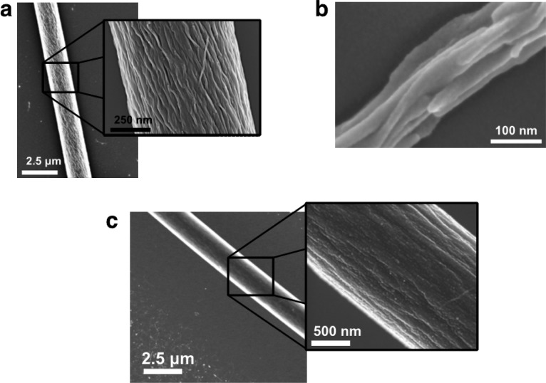
Electrospun fibers of PA 1 and 2 showed axial alignment of supramolecular polymers along the long axis of the fiber (Figure 4). Scanning electron microscopy (SEM) revealed that electrospun fibers of PA 1 were composed of individual nanostructures approximately 20 nm in width: these dimensions are consistent with dimensions observed in Cryo-TEM (Figure 1). The morphology of individual nanostructures appeared nonuniform in diameter and may retain the assembled twisted nanoribbon morphology (Figure 4a). Some thin electrospun fibers (<200 nm), from 2 wt % solutions, for example, were composed of textured structures reminiscent of bundles of twisted nanoribbons (Figure 4b). This ribbon-like structure was also observed in electrospun systems of poly (ether imide) in hexafluoroisopropanol.34 PA 2 produced electrospun fibers composed of bundles of cylindrical PA nanofibers approximately 50 nm wide (Figure 4c). Even though both ribbons and cylindrical nanofibers would be suitable for biological applications, the cylindrical morphology is more effective at proper signal presentation.
Figure 4.
SEM imaging of electrospun fibers from 2 wt % solutions of (a, b) PA 1 and (c) PA 2. Fibers are composed of highly aligned supramolecular polymers. (b) PA 1 forms assemblies of twisted nanoribbons that are maintained through the electrospinning process.
Surface Coatings of Electrospun PAs
Like conventional polymeric materials, electrospun PA fibers can be deposited on a myriad of surfaces, including medically relevant devices, like stents (Figure 5a), or substrates such as glass (Figure 5b) or silicon (Figure 5c). With practical applications in mind, the electrospinning of PAs could be used to improve cell adhesion to surfaces or elicit a tailored biological response to medical devices by utilizing PAs with bioactive epitopes. However, these studies are outside the scope of the work presented here. Attempts to form free-standing films of electrospun PAs yielded materials that were not mechanically robust.
Figure 5.
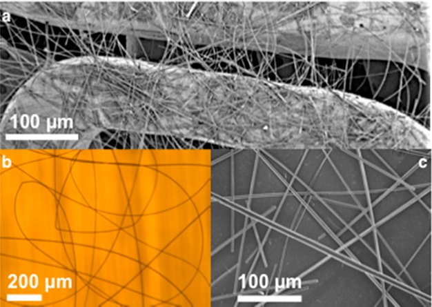
Electrospinning of PA fibers on (a) metallic coronary stent (PA 1), (b) glass (PA 1), and (c) silicon (PA 2).
Optical Imaging of Electrospun PAs
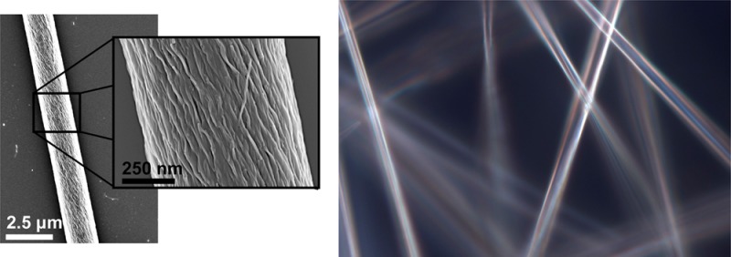
The fibers produced by electrospinning PAs were examined by optical birefringence as well. PA solutions and aligned monodomains of PA gels32 show birefringence under crossed polarizers (Figure 6). When two oriented fibers are laid orthogonally on top of each other, light is fully extinguished: this observation illustrates the high degree of alignment of nanostructures within the fiber. The large shear force at the Taylor cone aligns the supramolecular polymers along the spinning direction, resulting in electrospun fibers composed of highly aligned, densely packed nanostructures.
Figure 6.
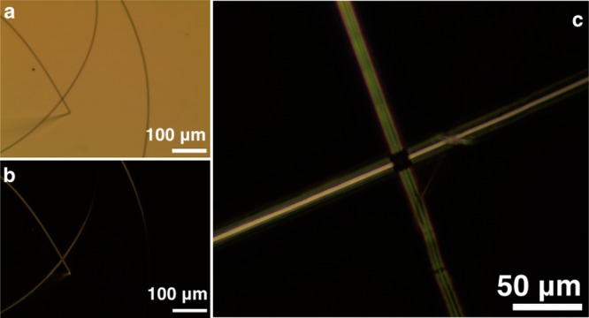
Optical imaging of electrospun PA fibers (a) without polarizers (PA 1), (b) with cross polarizers (PA 1), and (c) cross polarizers (PA 2). Birefringence with cross polarizers indicates that supramolecular polymers are highly aligned along the fiber.
Furthermore, electrospun PA materials are a good candidate for applications in regenerative medicine. Preliminary studies demonstrated that cells are able to adhere to nonbiological materials, such as indium tin oxide, when a coating of electrospun PA 1 is present. To prove the bioactivity of the fibers, parameters like cell viability, morphology (a measure of adhesion), and even stem cell differentiation could be studied. Additionally, PA 2 nucleated the growth of amorphous calcium phosphate from calcium-enriched media, which could provide a bioactive surface to promote bone mineralization (Supporting Information). These results suggest that the combination of peptide amphiphile self-assembly and electrospinning could produce new types of functional coatings for biological applications.
Conclusions
Peptide amphiphiles that self-assemble into nanofibers are known to be highly bioactive. In this work we have demonstrated the electrospinning of these functional supramolecular polymers into micrometer-scale fibers without any carrier polymer or template. These PAs self-assemble into functional supramolecular polymers with properties that allow them to be electrospun. Additionally, the solution-phase assembly of cylindrical nanofibers or twisted ribbons in water offers a strategy to create new fibrous biomaterials. These supramolecular polymers may find new applications to create bioactive surfaces for implantable devices, sutures, and scaffolds for tissue regeneration.
Acknowledgments
This work was supported by NIH NIBIB Grant No. 5R01EB003806-08 and NIH NIDCR Grant No. 5R01DE015920-07. A.S.T. was supported by a fellowship from the Initiative for Sustainability and Energy at Northwestern (ISEN) and Non-Equilibrium Research Center (NERC). We thank Prof. Jiaxing Huang (Northwestern) for use of his electrospinning setup, Prof. Ken Shull (Northwestern) for use of equipment to measure surface tension, and Prof. Chad Mirkin (Northwestern) for use of equipment to measure solution conductivity.
Supporting Information Available
Images and discussion of applications of electrospun materials. This material is available free of charge via the Internet at http://pubs.acs.org.
The authors declare no competing financial interest.
Funding Statement
National Institutes of Health, United States
Supplementary Material
References
- Li D.; Wang Y.; Xia Y. Nano Lett. 2003, 381167–1171. [Google Scholar]
- Reneker D. H.; Chun I. Nanotechnology 1996, 73216–223. [Google Scholar]
- Fong H.; Chun I.; Reneker D. H. Polymer 1999, 40164585–4592. [Google Scholar]
- Han T.; Yarin A. L.; Reneker D. H. Polymer 2008, 4961651–1658. [Google Scholar]
- Reneker D. H.; Yarin A. L. Polymer 2008, 49102387–2425. [Google Scholar]
- Deitzel J. M.; Kleinmeyer J. D.; Hirvonen J. K.; Tan N. C. B. Polymer 2001, 42198163–8170. [Google Scholar]
- Li W. J.; Tuli R.; Huang X. X.; Laquerriere P.; Tuan R. S. Biomaterials 2005, 26255158–5166. [DOI] [PubMed] [Google Scholar]
- Li W. J.; Tuli R.; Okafor C.; Derfoul A.; Danielson K. G.; Hall D. J.; Tuan R. S. Biomaterials 2005, 266599–609. [DOI] [PubMed] [Google Scholar]
- Matthews J. A.; Wnek G. E.; Simpson D. G.; Bowlin G. L. Biomacromolecules 2002, 32232–238. [DOI] [PubMed] [Google Scholar]
- Li C. M.; Vepari C.; Jin H. J.; Kim H. J.; Kaplan D. L. Biomaterials 2006, 27163115–3124. [DOI] [PubMed] [Google Scholar]
- Cashion M. P.; Li X. L.; Geng Y.; Hunley M. T.; Long T. E. Langmuir 2010, 262678–683. [DOI] [PubMed] [Google Scholar]
- McKee M. G.; Layman J. M.; Cashion M. P.; Long T. E. Science 2006, 3115759353–355. [DOI] [PubMed] [Google Scholar]
- Singh G.; Bittner A. M.; Loscher S.; Malinowski N.; Kern K. Adv. Mater. 2008, 20122332–2336. [Google Scholar]
- Yan X. Z.; Zhou M.; Chen J. Z.; Chi X. D.; Dong S. Y.; Zhang M. M.; Ding X.; Yu Y. H.; Shao S.; Huang F. H. Chem. Commun. 2011, 47257086–7088. [DOI] [PubMed] [Google Scholar]
- Celebioglu A.; Uyar T. Langmuir 2011, 27106218–6226. [DOI] [PubMed] [Google Scholar]
- Grodowska K.; Parczewski A. Acta Pol. Pharm. 2010, 6713–12. [PubMed] [Google Scholar]
- Cui H.; Muraoka T.; Cheetham A. G.; Stupp S. I. Nano Lett. 2009, 93945–951. [DOI] [PMC free article] [PubMed] [Google Scholar]
- Hartgerink J. D.; Beniash E.; Stupp S. I. Proc. Natl. Acad. Sci. U.S.A. 2002, 9985133–5138. [DOI] [PMC free article] [PubMed] [Google Scholar]
- Hartgerink J. D.; Beniash E.; Stupp S. I. Science 2001, 29455471684–1688. [DOI] [PubMed] [Google Scholar]
- Boekhoven J.; Stupp S. I. Adv. Mater. 2014, 10.1002/adma.2013046066. [DOI] [PMC free article] [PubMed] [Google Scholar]
- Tysseling V. M.; Sahni V.; Pashuck E. T.; Birch D.; Hebert A.; Czeisler C.; Stupp S. I.; Kessler J. A. J. Neurosci. Res. 2010, 88143161–3170. [DOI] [PMC free article] [PubMed] [Google Scholar]
- Rajangam K.; Behanna H. A.; Hui M. J.; Han X.; Hulvat J. F.; Lomasney J. W.; Stupp S. I. Nano Lett. 2006, 692086–2090. [DOI] [PubMed] [Google Scholar]
- Huang Z.; Newcomb C. J.; Bringas P. Jr; Stupp S. I.; Snead M. L. Biomaterials 2010, 31359202–9211. [DOI] [PMC free article] [PubMed] [Google Scholar]
- Mata A.; Geng Y. B.; Henrikson K. J.; Aparicio C.; Stock S. R.; Satcher R. L.; Stupp S. I. Biomaterials 2010, 31236004–6012. [DOI] [PMC free article] [PubMed] [Google Scholar]
- Shah R. N.; Shah N. A.; Lim M. M. D.; Hsieh C.; Nuber G.; Stupp S. I. Proc. Natl. Acad. Sci. U.S.A. 2010, 10783293–3298. [DOI] [PMC free article] [PubMed] [Google Scholar]
- Webber M. J.; Tongers J.; Newcomb C. J.; Marquardt K. T.; Bauersachs J.; Losordo D. W.; Stupp S. I. Proc. Natl. Acad. Sci. U.S.A. 2011, 1083313438–13443. [DOI] [PMC free article] [PubMed] [Google Scholar]
- Stendahl J. C.; Kaufman D. B.; Stupp S. I. Cell Transplant 2009, 1811–12. [DOI] [PMC free article] [PubMed] [Google Scholar]
- Bond C. W.; Angeloni N.; Harrington D.; Stupp S.; Podlasek C. A. J. Sex. Med. 2013, 103730–737. [DOI] [PMC free article] [PubMed] [Google Scholar]
- Lee S. S.; Huang B. J.; Kaltz S. R.; Sur S.; Newcomb C. J.; Stock S. R.; Shah R. N.; Stupp S. I. Biomaterials 2013, 342452–459. [DOI] [PMC free article] [PubMed] [Google Scholar]
- Li D.; Xia Y. N. Adv. Mater. 2004, 16141151–1170. [Google Scholar]
- Theron A.; Zussman E.; Yarin A. L. Nanotechnology 2001, 123384–390. [Google Scholar]
- Zhang S. M.; Greenfield M. A.; Mata A.; Palmer L. C.; Bitton R.; Mantei J. R.; Aparicio C.; de la Cruz M. O.; Stupp S. I. Nat. Mater. 2010, 97594–601. [DOI] [PMC free article] [PubMed] [Google Scholar]
- Pashuck E. T.; Cui H. G.; Stupp S. I. J. Am. Chem. Soc. 2010, 132176041–6046. [DOI] [PMC free article] [PubMed] [Google Scholar]
- Koombhongse S.; Liu W. X.; Reneker D. H. J. Polym. Sci., Polym. Phys. 2001, 39212598–2606. [Google Scholar]
Associated Data
This section collects any data citations, data availability statements, or supplementary materials included in this article.


