Short abstract
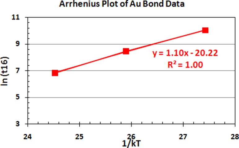
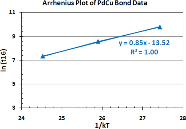
Wearout reliability and high temperature storage life (HTSL) activation energy of Au and Pd-coated Cu (PdCu) ball bonds are useful technical information for Cu wire deployment in nanoscale semiconductor device packaging. This paper discusses the influence of wire type on the wearout reliability performance of Au and PdCu wire used in fine pitch BGA package after HTSL stress at various aging temperatures. Failure analysis has been conducted to identify the failure mechanism after HTSL wearout conditions for Au and PdCu ball bonds. Apparent activation energies (Eaa) of both wire types are investigated after HTSL test at 150 °C, 175 °C and 200 °C aging temperatures. Arrhenius plot has been plotted for each ball bond types and the calculated Eaa of PdCu ball bond is 0.85 eV and 1.10 eV for Au ball bond in 110 nm semiconductor device. Obviously Au ball bond is identified with faster IMC formation rate with IMC Kirkendall voiding while PdCu wire exhibits equivalent wearout and or better wearout reliability margin compare to conventional Au wirebond. Lognormal plots have been established and its mean to failure (t50) have been discussed in this paper.
Keywords: wearout reliability, apparent activation energy, high temperature storage life, arrhenius plot, lognormal plot, semiconductor device
1. Introduction
Cu wirebonding is widely adopted in recent nanoelectronic packaging due to its conductivity, material properties, and cost effectiveness. However, there are few key technical barriers to be seriously considered in order to fully transition from Au to Cu ball bonds in semiconductor packages. Gan et al. [1–4] has reported the key challenges of Cu wirebonding deployment in nanoelectronic packaging while Tan et al. [5,6], Yu et al. [7] and Lin et al. [8] investigated the technical barriers and failure mechanism of bare Cu and Pd-coated Cu wirebonding in semiconductor packaging. Harman [9] reported the challenges and moisture reliability of Cu wirebonding and Au ball bond Kirkendall micro-voiding in early years. Hang et al. [10] investigated post isothermal aging of CuAl ball bonds mainly are attributed to CuAl IMC interface corrosion and induce interface microcracking. However, there are limited researchers carry out study on the wearout reliability of Palladium-coated Cu wire, bare Cu wire or Au wire bonds in nanoelectronics device packaging. It is a crucial to conduct knowledge based reliability studies and understands the wearout reliability models [4,8,11–13] and its associated failure mechanism with Cu wirebonding in nanoelectronic device packaging which will ensure successful Cu wirebonding deployment in high pin count and nanoscale devices. McPherson [14] laid out the time to failure reliability modeling in semiconductor physics and reliability stressing. Gan et al. [4] characterized the wearout reliability on Au and Pd-coated Cu ball bonds used in fineline BGA flash memory packages. There are few researchers investigated and compared the IMC diffusion kinetics and calculated the apparent activation energy for Cu and Au ball bond IMC after high temperature aging [8,12,15–25]. Wearout reliability of a product is defined as the staged whereby a product or part's reliability would give way at its weakest interconnect or link in a system. In this study, the Au and Pd-coated Cu bond reliability under different HTSL aging temperature to investigate the thermal activated processes in semiconductor device packaging. Wearout reliability plots, apparent activation energy (Eaa) and post HTSL ball shear and wire pull strength are investigated in the testing of HTSL. The obtained values of Au and PdCu ball bonds Eaa are compared to previous literature studies [11,12]. Failure mechanism at bond interface is established accordingly.
2. Experiment
2.1. Materials and Preparation of Au and Pd-Coated Cu Wirebond Package With 110 nm Device.
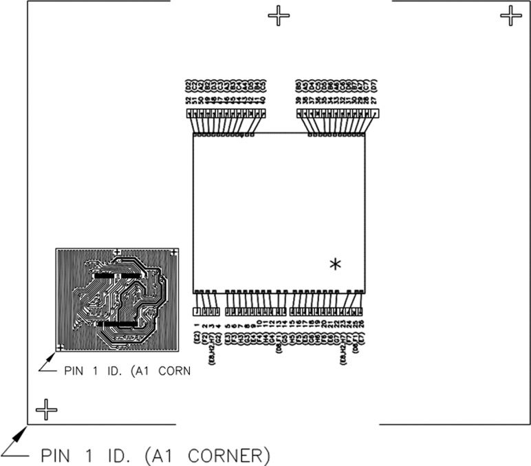
The key materials used include 0.8 mil Pd-coated Cu wire and 0.8 mil 4N (99.99% purity) Au wire, fine pitch BGA package, 110 nm device which to be packed in fortified Fineline BGA package, green (<20 ppm Chloride in content) in molding compound and substrate. All direct materials used in this evaluation study are 110 nm, low-k device (with top Al metallization bondpad) for packaging purpose. In this HTSL, wearout reliability study, there are total six legs comprising of Pd-coated Cu wire and 4 N Au wire bonded on Fine pitch 64-ball BGA packages on a 2L substrate. Sample size used is 40 units for each aging stresses. The corresponding stress tests and its conditions are tabulated in Table 1. After electrical test, good samples were then subjected for HTSL stress testing per JESD22A-103D [26] at 150 °C, 175 °C and 200 °C aging temperatures. Electrical testing was conducted after each hour's readout of aging temperatures to check Au and PdCu ball bond integrity in terms of its first ball bond reliability. The units are stressed until wearout failures and reliability plots are analyzed. Results of HTSL wearout reliability test of the evaluation are tabulated in Table 1. The apparent activation energies (Eaa) of Au and PdCu ball bonds were determined from Arrhenius plots (Figs. 9 and 10) and tabulated in Table 2. Figure 1 shows the wirebond interconnection in FBGA 64 package of our test vehicle.
Table 1.
Characteristics of the lognormal plots of various aging temperatures (Au and PdCu wires used in 110 nm device)
| Wire type | Sample size (units) | Aging temperature | tfirst (hr) | t16 (hr) | t50 (hr) | σ |
|---|---|---|---|---|---|---|
| PdCu | 40 | 150 °C | 4800 | 5239 | 6072 | 0.148 |
| PdCu | 40 | 175 °C | 4500 | 5780 | 7619 | 0.276 |
| PdCu | 40 | 200 °C | 1500 | 1743 | 2726 | 0.448 |
| Au | 40 | 150 °C | 3500 | 3024 | 6561 | 0.775 |
| Au | 40 | 175 °C | 3800 | 6200 | 5195 | 0.326 |
| Au | 40 | 200 °C | 1000 | 971 | 1153 | 0.172 |
Fig. 9.
Arrhenius plots of Au ball bond data against 1/kT aging time used in 110 nm semiconductor device
Fig. 10.
Arrhenius plots of PdCu ball bond data against 1/kT aging time used in 110 nm semiconductor device
Table 2.
Summary of apparent activation energies and associated failure mechanisms comparing Au and PdCu ball bonds used in semiconductor device
Fig. 1.
Wirebond interconnection in FBGA 64 package
2.2. Reliability Testing of Nano Electronic Package.
First, samples were heated loaded in HTSL chambers according to its aging conditions as tabulated in Table 1. After each hour, open, short, and device datasheet functionality were verified by using a commercial electrical tester. Microstructure of failing units was determined by using cross section and scanning electron microscopy (SEM).
3. Results and Discussion
3.1. Wearout Reliability Studies Comparing Au and PdCu Ball Bonds.
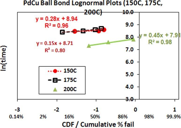
Wearout reliability of Au and PdCu ball bond are fitted to reliability plotting such as lognormal distribution. The characteristics of lognormal plots of both Au and PdCu ball bonds are tabulated in Table 1. It covers the three high temperature aging temperatures in HTSL wearout reliability stresses for each wire types. It clearly indicates the PdCu ball bond exhibits higher wearout reliability margins in terms of HTSL stresses with higher first hour (tfirst) to failure, time-to-failure at 16% failure rate (t16) and mean time to failure hours (t50) compare to conventional Au ball bond. Both PdCu and Au ball bonds exceed JEDEC acceptance hours. The respective mean time to failure hours (t50) and location parameter (σ) of each lognormal distribution are calculated and shown in Table 1. All the six reliability plots belong to wear out reliability region in conventional reliability bathtub curve.
3.1.1. Lognormal Plots Analysis.
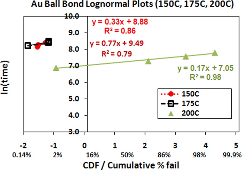
Lognormal plot is used in the extend HTSL reliability analysis whereby ln (time) against CDF (cumulative distribution function) or cumulative percentage to failure is plotted in Figs. 2 and 3. Cu wire is well-identified as a less corrosion resistant material compared to Au wire in nanoelectronic packaging. Moisture reliability of bare Cu wire is identified as key technical barrier of Cu wire deployment in nanoelectronic packaging. Cu ball bond open is one of the bonding failures attributed to interface CuAl IMC microcracking [1–3,11,19,20]. Figure 2 indicates the wearout reliability lognormal plot of PdCu ball bond. In our evaluation, PdCu lognormal plots higher reliability margin in HTSL aging tests (Table 1).
Fig. 2.
High temperature aging (150 °C, 175 °C, 200 °C) lognormal plots and its characteristics of PdCu used in 110 nm device FBGA 64 package
Fig. 3.
High temperature aging (150 °C, 175 °C, 200 °C) lognormal plots and its characteristics of Au used in 110 nm device FBGA 64 package
Figure 3 reveals wearout reliability plots fitted to lognormal distribution of Au ball bond. PdCu ball bonds shows better aging hours to failure compare to Au ball bonds on 110 nm device, FBGA 64 package. This is owing to the slower PdCu-Al IMC formation compares AuAl IMC formation and results in better long term reliability [6,9,20–22].
3.2. Wearout Failure Mechanisms
3.2.1. Effects of Wire Type Used in Nanoelectronic Packaging.
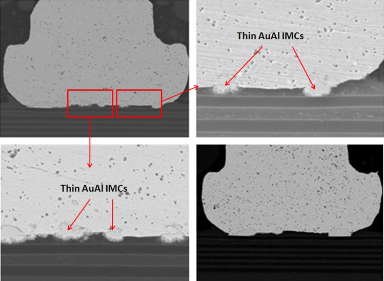
The effect of wire type used in nanoelectronic device packaging affects the long term reliability of semiconductor packages. The wearout failure mechanisms of CuAl interface oxidation and microcracking (which induce Cu ball bond opens) are mainly owing to CuAl IMC interface oxidation [1,5,7,8,11,12,16,19]. While the AuAl IMC interfacial oxidation and Kirkendall micro voiding are widely reported by industrial and academic researchers [9,21,23,25]. The as bonded stage of Au ball bonds are observed with thin AuAl IMC formation and no Kirkendall micro voiding is found in microstructure analysis (see Fig. 4).
Fig. 4.
SEM images show thin AuAl IMC formation on as bonded stage of Au wirebond package prior to reliability stress
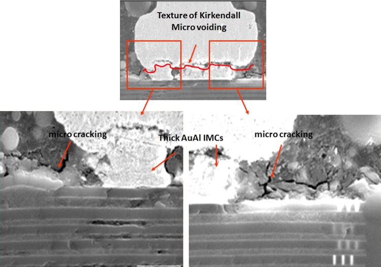
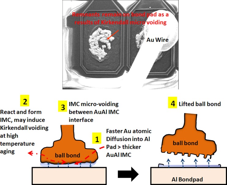
In our study, the typical AuAl IMC interface oxidation and microvoiding is indicated in Fig. 5 after 200 °C 1500 h aging stress. The whole fine line AuAl IMC microcracking and micro-voiding occurs along the whole AuAl IMC interface. Thicker AuAl IMC layer is formed beneath Au ball bond and micro cracking is observed after 1500 h of HTSL test. Kirkendall micro voiding is found beneath Au ball bond in cross-section analysis and further package decapsulation is conducted to confirm the Kirkendall micro voiding event (as shown in Fig. 6).
Fig. 5.
Typical Au ball bond IMC voiding and cracks post extended HTSL stress (1500 hr, 200 °C). Thicker AuAl IMC is formed with sign of Kirkendall microvoiding, microcracking beneath Au ball bond after long duration of HTSL test.
Fig. 6.
Proposed failure mechanism of AuAl Kirkendall micro voiding and caused lifted ball bond
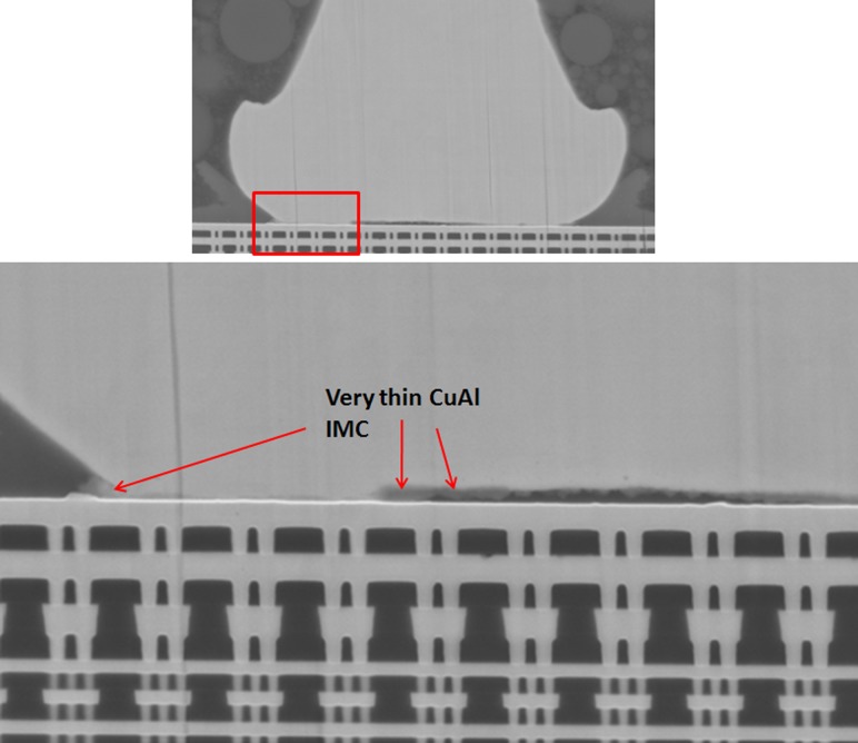
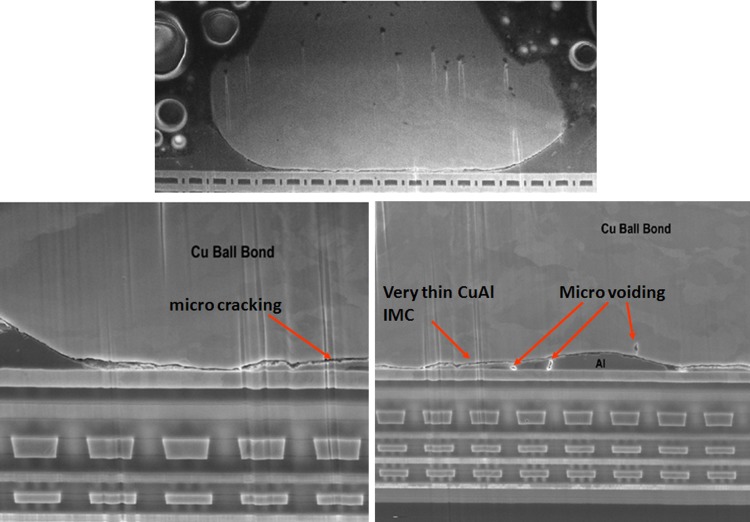
For Cu ball bond as bonded microstructural analysis, we found almost no CuAl IMC formation and no signature of micro cracking beneath Cu ball bond (see Fig. 7) on unit prior to HTSL reliability testing. CuAl IMC micro cracking and micro voiding are formed after extended duration of 1500 h HTSL test (as indicated in Fig. 8). Kirkendall micro voiding event is not found in our micro structural analysis. Figure 8 illustrates the typical HTSL 200 °C 1500 h aging and its CuAl IMC interface oxidation and microcracking most probably attributed to Oxygen attacking the edge of Cu ball bond region. Usually the Pd coated layer will be dissolved during CuAl Pd IMC formation in PdCu ball bonds. Oxygen gas will penetrate into the edge of Cu ball bond and induce dry oxidation of CuAl IMC (in this case the majority of IMC are Cu9Al4 and CuAl2) as shown in Eqs. (2) and (3) [3]. Dry oxidation will produce CuO which is resistive layer in CuAl interface (as shown in Eq. (1)).
Fig. 7.
SEM images show very thin CuAl IMC formation on as bonded stage of Cu wirebond package prior to reliability stress. No microcracking beneath PdCu ball bond.
Fig. 8.
Typical CuAl IMC microcracks post extended HTSL stress (1500 hr, 200 °C aging). Signs of micro cracking and micro voiding are observed.
Equation (1) indicates the hydrolysis of Cu9Al4 into Al2O3 and out gassing
| (1) |
| (2) |
| (3) |
Cracking of the interface of Cu to the Cu IMC might be due to stress induce microcracking as a results of CuAl IMC oxidation (as shown in Eqs. (2) and (3)) in between Cu IMC to Cu ball bonds. Cracking usually starts at Cu ball bond periphery and will propagate towards center of Cu ball bond [1,3,8,12,16].
Representative PdCu ball bond cross-section SEM image confirms CuAl interface fineline cracking as shown in Fig. 8. The micro cracking would probably caused electrical opens in HTSL stress for PdCu. The failure mechanism of Au ball bond is found dissimilar to PdCu ball bond with similar fineline microcracking along the IMC region and caused opens.
3.3. Determination of Apparent Activation Energies of Au and PdCu Ball Bonds in HTSL Test.
In this paper, thermal aging test was used to accelerate the HTSL test of PdCu and Au ball bonds in semiconductor packaging. The required activation energies (Eaa) of interdiffusion of Cu and Au atoms in Al were modeled by using Arrhenius model. The fundamental basis of thermal activation is based on the probability of ascending a potential energy barrier due to Maxwell–Boltzmann energy distribution. This physical explanation was actually anticipated by Arrhenius work on chemical reaction rates, which one would simple substitute the Rydberg gas constant for the Boltzmann constant and use different units. Thermal activated processes are modeled by Arrhenius equation and it is given by Eq. (4)
| (4) |
| (5) |
where Ro is the rate constant characteristics of infinite temperature, Eaa refers to apparent activation energy in eV/atom for physics units or Kcal/mole for chemical units, k is the Boltzmann constant, 8.62 × 10⁻⁵ eV/Kelvin, R is the Rydberg gas constant, 23,063 cal/mole-kelvin and T is the temperature in Kelvin.
Using Eq. (5), the acceleration factor, AF for T1 versus T2 is as follows:
| (6) |
It is noted that the acceleration factor is sensitive to the value for the apparent activation energy, Eaa and the temperature difference.
The apparent activation energy, Eaa which is temperature dependence can be determined by plotting graph ln (lifetime of ball bonds) versus 1/kT as in Eq. (7). Graph ln T (lifetime) versus (1/T) can be plotted by using Eq. (8).
| (7) |
| (8) |
Where self diffusion coefficient, Ro is a constant, Eaa is activation energy in eV for the diffusion process, R is molar gas constant in Jmol−1K−1 and T is lifetime of ball bonds. The apparent activation energy, Eaa can be calculated from the gradient of the plot ln T versus 1/kT.
Table 2 tabulates the results of Eaa and typical wearout failure mechanisms of Au and PdCu ball bond after HTSL stress of our studies compare to previous engineering works conducted by researchers [11,12]. In our evaluation, the values obtained for Eaa (in eV) of Au ball bond is similar to value published in JEDEC JEP112 [11] while Eaa of PdCu ball bond is slightly higher than bare Cu ball bond. The typical wearout failure mechanism of PdCu ball bond is CuAl microcracking and Kirkendall voiding is observed in Au ball bond after HTSL aging tests. These wearout failures are similar to previous works done [11,12]. Hence it can be concluded that the Au atom diffuses much faster than PdCu atoms in Al metallization and induce Kirkendall voiding after aging tests. The lifetime for Au ball bonds derived from lognormal plot is observed with lower lifetime compare to PdCu ball bond in 110 nm semiconductor device.
Figures 9 and 10 indicate the respective Au and PdCu ball bonds Arrhenius plots obtained in our measurement for 150 °C, 175 °C and 200 °C aging temperatures. It clearly indicates that Au atoms with higher Eaa for HTSL degradation, Eaa of 1.10 eV against 0.85 eV for PdCu ball bonds on 110 nm semiconductor device packaging.
3.4. Post HTSL Stresses Ball Bond Shear and Wire Pull Strength Analysis (Au Versus PdCu Ball Bonds).
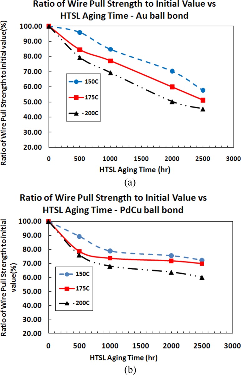
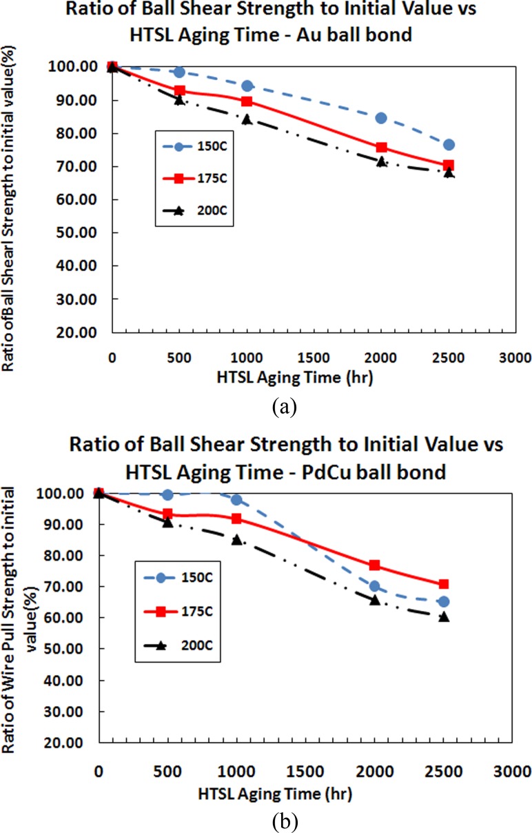
Mechanical strength (ball bond shear and wire pull strength) of PdCu and Au ball bond are analyzed accordingly post extended hours of HTSL reliability stresses. The main objective is to confirm if the ball bond are robust even after HTSL long time reliability stress testing. The typical minimum shear strength (in g) and minimum wire pull strength (in gf) of 0.80 mils wire diameter are 14 g and 2.5 gf, respectively. The mean values of ball bond shear and wire pull strength are analyzed and compared to time zero before stress testing (in ratio of its original value to after HTSL aging test).
It is observed that the wire pull and ball shear strength of PdCu ball bonds degraded more than Au ball bonds after HTSL 500 h, 1000 h and 2000 h. However, it is still far exceeding the minimum shear and pull strength value of 14 g and 2.5 gf. In general, the magnitude of degradation is observed larger with incremental of aging temperatures from 150 °C to 200 °C (as shown in Figs. 11(a), 11(b), 12(a) and 12(b). Figures 12(a) and 12(b) indicate similar degradation trend for ball shear strength comparing Au and PdCu ball bonds. PdCu ball bonds exhibit faster degradation trend compare to Au ball bonds on 110 nm semiconductor device.
Fig. 11.
Plots of ratio of wire pull strength to its initial value against aging time of various aging temperatures for (a) Au wire and (b) PdCu Wire
Fig. 12.
Plots of ratio of wire pull strength to its initial value against aging time of various aging temperatures for (a) Au wire and (b) PdCu Wire
4. Conclusion
In Au and PdCu wire bonding evaluations on 110 nm devices, we have successfully investigated the HTSL wearout reliability margins and determined the apparent activation energy, Eaa of both wire types used in nanoscale semiconductor packaging in HTSL test.
The technical findings are summarized in following:
-
(1)
PdCu ball bond exhibits higher hours to failure (Lognormal fitted distribution) compared to Au ball bonds in HTSL long term aging stress in wearout reliability plots. This might be due to the lower Cu atoms diffusion into Al atoms for IMC formation compare to Au atoms diffusion into Al atomic for Au ball bond and observed with Kirkendall voiding for Au ball bonds.
-
(2)
Wearout failure mechanism of HTSL stress testing belong to CuAl interface oxidation and microcracking for PdCu ball bonds and Cu Al Kirkendall voiding and microcracking of Au ball bonds which induce electrical ball bond opens.
-
(3)
The values obtained for Eaa (in eV) of Au ball bonds (1.10 eV) is similar to value indicated in JEDEC JEP112 standard [11] while Eaa of PdCu ball bond (0.85 eV) close to value reported by Classe et al. [12].
-
(4)
It clearly indicates that au atoms diffuse faster than PdCu atoms in al metallization of 110 nm device
-
(5)
It is observed that the wire pull and ball shear strength of PdCu ball bonds degraded more than Au ball bonds after HTSL 500 h, 1000 h and 2000 h. However, it is still far exceeding the minimum shear and wire pull strength value of 14 g and 2.5 gf respectively. In general, the magnitude of degradation is observed larger with incremental of aging temperatures from 150 °C to 200 °C (as shown in Figs. 11(a), 11(b), 12(a) and 12(b)).
Acknowledgment
The authors would like to take this opportunity to thank Spansion management (Gene Daszko, Tony Reyes, and Chong Hin Lian) for their management support for the paper publication.
Contributor Information
C. L. Gan, Spansion (Penang) Sdn Bhd., Phase II Free Industrial Zone, 11900 Bayan Lepas, Penang, Malaysia; Institute of Nano Electronic Engineering (INEE), Universiti Malaysia Perlis, 01000 Kangar, Perlis, Malaysia, e-mail: clgan_pgg@yahoo.com.
U. Hashim, Institute of Nano Electronic Engineering (INEE), Universiti Malaysia Perlis, 01000 Kangar, Perlis, Malaysia
References
- [1]. Gan, C. L. , Toong, T. T. , Lim, C. P. , and Ng, C. Y. , 2010, “Environmental Friendly Package Development by Using Copper Wire,” 34th IEEE/CPMT International Electronic Manufacturing Technology Symposium (IEMT), Malacca, Malaysia, November 30–December 2.10.1109/IEMT.2010.5746747
- [2]. Gan, C. L. , Ng, E. K. , Chan, B. L. , and Hashim, U. , 2012, “Reliability Challenges of Cu Wire Deployment in Flash Memory Packaging,” 7th International Microsystems, Packaging, Assembly and Circuits Technology Conference (IMPACT), Taipei, Taiwan, October 24–26, pp. 236–239.10.1109/IMPACT.2012.6420214
- [3]. Gan, C. L. , Ng, E. K. , Chan, B. L. , Hashim, U. , and Classe, F. C. , 2012, “Technical Barriers and Development of Cu Wirebonding in Nanoelectronic Device Packaging,” J. Nanomater., 173025, pp. 1–710.1155/2012/173025 [Google Scholar]
- [4]. Gan, C. L. , Ng, E. K. , Chan, B. L. , Kwuanjai, T. , and Hashim, U. , 2012, “Wearout Reliability Study of Cu and Au Wires Used in Flash Memory Fine Line BGA Package,” 7th International Microsystems, Packaging, Assembly and Circuits Technology Conference (IMPACT), Taipei, Taiwan, October 24–26, pp. 232–235.10.1109/IMPACT.2012.6420213
- [5]. Tan, C. W. , Daud, A. R. , and Yarmo, A. M. , 2002, “Corrosion Study at Cu-Al Interface in Microelectronics Packaging,” J. Appl. Surf. Sci., 191, pp. 67–7310.1016/S0169-4332(02)00150-2 [Google Scholar]
- [6]. Tan, C. W. , and Daud, A. R. , 2002, “The Effects of Aged Cu-Al Intermetallics to Electrical Resistance in Microelectronics Packaging,” Microelectron. Int., 19(2), pp. 38–4310.1108/13565360210427889 [Google Scholar]
- [7]. Yu, C.-F. , Chan, C.-M. , Chan, L.-C. , and Hsieh, K.-C. , 2011, “Cu Wire Bond Microstructure Analysis and Failure Mechanism,” Microelectron. Reliab., 51, pp. 119–12410.1016/j.microrel.2010.04.022 [Google Scholar]
- [8]. Lin, Y.-W. , Ke, W.-B. , Wang, R.-Y. , Wang, I.-S. , Chiu, Y.-T. , Lu, K.-C. , Lin, K.-L. , and Lai, Y.-S. , 2012, “The Influence of Pd on the Interfacial Reactions Between the Pd-Plated Cu Ball Bond and Al Pad,” Surf. Coat. Technol. (in press).10.1016/j.surfcoat.2012.07.033 [Google Scholar]
- [9]. Harman, G. G. , 1989, Wirebonding in Microelectronics: Processes, Reliability, and Yield, 2nd ed., McGraw-Hill, New York, pp. 50–126 [Google Scholar]
- [10]. Hang, C. J. , Wang, C. Q. , Mayer, M. , Tian, Y. H. , Zhou, Y. , and Wang, H. H. , 2008, “Growth Behavior of Cu/Al Intermetallic Compounds and Cracks in Copper Ball Bonds During Isothermal Aging,” Micron. Reliab., 48, pp. 416–42410.1016/j.microrel.2007.06.008 [Google Scholar]
- [11].JEDEC Specification, 2010, “Failure Mechanisms and Models for Semiconductor Devices,” Paper No. JEP 122 2010. [Google Scholar]
- [12]. Classe, F. C. , and Gaddamraja, S. , 2011, “Long Term Isothermal Reliability of Copper Wire Bonded to Thin 6.5 μm Aluminum,” IEEE International Reliability Physics Symposium (IRPS), Monterey, CA, April 10–14.10.1109/IRPS.2011.5784557
- [13].JEDEC Standard, 2012, “Stress Test Driven Qualification of Integrated Circuits, Paper No. 2012 JESD 47.
- [14]. McPherson, J. W. , 2010, Reliability Physics and Engineering: Time to Failure Modelling, 1st ed., Springer, New York, pp. 258–261 [Google Scholar]
- [15]. Li, J. , Wang, F. , Han, L. , and Zhong, J. , 2008, “Theoretical and Experimental Analysis of Atom Diffusion Characteristics on Wirebonding Interface,” J. Phys. D: Appl. Phys., 41(13), p. 135303.10.1088/0022-3727/41/13/135303 [Google Scholar]
- [16]. Xu, H. , Liu, C. , Silberschmidt, and Chen, Z. , 2010, “Growth of Intermetallic Compounds in Thermosonic Copper Wire Bonding on Aluminium Metallization,” J. Electron. Mater., 39(1), pp. 124–13110.1007/s11664-009-0951-8 [Google Scholar]
- [17]. Xu, H. , Liu, C. , Silberschmidt, V. V. , Pramana, S. S. , White, T. J. , and Chen, Z. , 2009, “A Re-Examination of the Mechanism of Thermosonic Copper Ball Bonding on Aluminium Metallization Pad,” Scr. Mater., 61(2), pp. 165–168.10.1016/j.scriptamat.2009.03.034 [Google Scholar]
- [18]. Xu, H. , Liu, C. , Silberschmidt, V. V. , Pramana, S. S. , White, T. J. , Chen, Z. , and Acoff, V. L. , 2011, “Behavior of Aluminum Oxide, Intermetallics and Voids in Cu–Al Wire Bonds,” Acta Mater., 59(14), pp. 5661–567310.1016/j.actamat.2011.05.041 [Google Scholar]
- [19]. Jeng, Y. R. , Aoh, J. H. , and Wang, C. M. , 2001, “Thermosonic Wirebonding of Gold Wire Onto Copper Pad Using the Saturated Interface Phenomena,” J. Phys. D: Appl. Phys., 34(24), pp. 3515–352110.1088/0022-3727/34/24/316 [Google Scholar]
- [20]. Kim, H. J. , Lee, J. Y. , and Paik, K. W. , 2003, “Effects of Cu/Al Intermetallic Compound (IMC) on Copper Wire and Aluminium Pad Bondability,” IEEE Trans. Compon. Packag. Technol., 26(2), pp. 367–37410.1109/TCAPT.2003.815121 [Google Scholar]
- [21]. Zulrich, C. M. , Hashibon, A. , Svoboda, J. , Elsasser, C. , Helm, D. , and Riedel, H. , 2011, “Diffusion Kinetics in Aluminium-Gold Bond Contacts From First Principles Density Functional Calculations,” Acta Mater., 59, pp. 7634–764410.1016/j.actamat.2011.08.021 [Google Scholar]
- [22]. Kim, S. H. , Park, J. W. , Hong, S. J. , and Moon, J. T. , 2010, “The Interface Behavior of the Cu-Al Bond System in High Humidity Conditions,” 12th Electronics Packaging Technology Conference (EPTC), Singapore, December 8–10, pp. 545–549.10.1109/EPTC.2010.5702699
- [23]. Breach, C. , and Wulff, F. , 2004, “New Observations on Intermetallic Compound Formation in Gold Ball Bonds: General Growth Pattern and Identification of Two Forms of Au4Al,” Microelectron. Reliab., 44(6), pp. 973–98110.1016/j.microrel.2004.02.013 [Google Scholar]
- [24]. Murali, S. , Srikanth, N. , and Charles, J. V., III , 2006, “An Evaluation of Gold and Copper Wirebonds on Shear and Pull Testing,” J. Electron. Packag., 128, pp. 192–20110.1115/1.2229214 [Google Scholar]
- [25]. Breach, C. , and Wulff, F. , 2006, “Oxidation of Au4Al in Unmolded Gold Ballbonds After High Temperature Storage (HTS) in Air at 175°C,” Microelectron. Reliab., 46, pp. 2112–212110.1016/j.microrel.2005.12.009 [Google Scholar]
- [26].JEDEC Specification, 2010, “High Temperature Storage Life,” Paper No. JESD22A-103D 2010.


