Abstract
Recreation of neural network in vitro with designed topology is a valuable tool to decipher how neurons behave when interacting in hierarchical networks. In this study, we developed a simple and effective platform to pattern primary neurons in array formats for interrogation of neural circuitry with single cell resolution. Unlike many surface-chemistry-based patterning methods, our NeuroArray technique is specially designed to accommodate neuron's polarized morphologies to make regular arrays of cells without restricting their neurite outgrowth, and thus allows formation of freely designed, well-connected, and spontaneously active neural network. The NeuroArray device was based on a stencil design fabricated using a novel sacrificial-layer-protected PDMS molding method that enables production of through-structures in a thin layer of PDMS with feature sizes as small as 3 µm. Using the NeuroArray along with calcium imaging, we have successfully demonstrated large-scale tracking and recording of neuronal activities, and used such data to characterize the spiking dynamics and transmission within a diode-like neural network. Essentially, the NeuroArray is a universal patterning platform designed for, but not limited to neuron cells. With little adaption, it can be readily interfaced with other interrogation modalities for high-throughput drug testing, and for building neuron culture based live computational devices.
The ability of neural tissues to carry out complex and concurrent processes results from the organization of connections between neurons inherent in these structures1,2. Understanding neural processes at the level of small neuron networks, and interactions between these circuits, is a powerful step in describing overall neural function3. Due to the unique complexity of the nervous system, it is important to isolate neuron circuits from their tissue context, allowing detailed study of brain functions, which have been useful in different aspects of modern neuroscience, including mechanistic elucidation of neural activities such as axonal pathfinding and synaptogenesis4,5, drug screening targeting neurological diseases6,7, and recreation of computational unit based on living cells8. Many of these studies depend on the availability of reproducible and reliable live neuronal networks with single cell addressability. Furthermore, the right connectivity matrix and the complex structural organization of neurons at different levels, from small network of a few neurons to large assembly of thousands of cells, enable neural circuits to carry out computations with extraordinary reliability on surprisingly short timescales3. Therefore, the goal to design well-controlled neural network outside human body has encouraged investigators to pursue means to create neuronal culture or interfaces by patterning neuron growth and connections in vitro.
Towards this goal, a significant milestone was the use of photolithography to pattern hydrophilic and hydrophobic compounds onto a silicon surface, providing microscale control over neuron attachment and growth9. Following this work, a variety of novel chemically patterned substrates10,11,12, soluble gradients4, physical structures13,14 were created using various nano-/microtechnologies to improve the organization of cultured neurons, capturing key aspects of the in vivo physiological environment and to provide better neural interface for probing and decoding network activities15,16. While tremendous advances have been made, most of the methods for patterning connection between neurons exert significant constraint to the growth of neuron cells, restricting axonal branching and dendritic arborization, which imposes much uncertainty to the health and physiological relevance of recreated neuron networks. In addition, it is also challenging for large-scale, long-term, parallel monitoring neuronal activities with single cell resolution in such well-controlled networks.
As an enabling technology to address these issues, we developed a universal three dimensional interface, NeuroArray, for reliable recreation of well organized neuron network, and for high-throughput interrogation of neural circuitry with single cell resolution. To accommodate the polarized morphology of neuronal cells, the three-dimensional structures of the device is specially designed to immobilize neuron somata in array format, which was made possible with a novel technique for fabricating silicone membrane with microscale through holes. Meanwhile, all neurites can freely grow without any constraint to make connections with neighboring cells. Using this platform, the cultured neurons can be organized into networks with spatially complex patterns without any surface chemistry. When coupled with optical microscopy of intracellular Ca2+ indicators, we performed automatic tracing and analysis of dynamic activities from hundreds of neurons in well-organized and spontaneously active networks. As the architecture of the neural network can have profound impacts on the function of individual neuronal cells2, the demonstrated in vitro model could be utilized to capture key aspects of the hierarchical structure of the in vivo neural circuitry. We believe that the NeuroArray technology will become an important tool for a wide range of neuroengineering applications, including basic research of neuronal functions such as synaptic connection and plasticity, high-throughput drug testing using in vitro neuron cultures, as well as reverse engineering neural microcircuitry in complex networks to create highly efficient, robust, and live computational devices.
Results
Design and fabrication of the NeuroArray
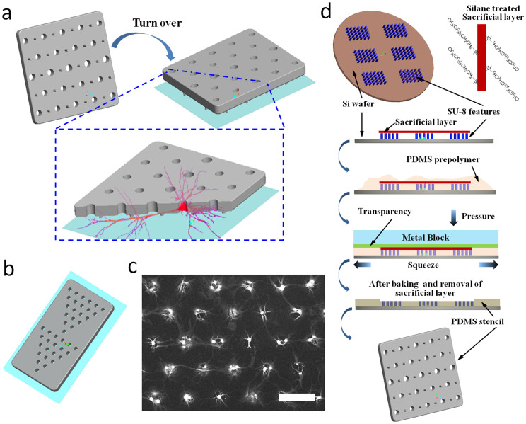
Due to polarized morphology and complex 3D organization, cellular processes in neurons are inherently challenging to manipulate and visualize. Especially for parallel interrogation of neural circuitry, it is critical to identify and keep tracking of specific neurons throughout specific experimental windows. Our NeuroArray technique was used to address this challenge by arraying neuronal cells to form patterned networks without restricting their developmental processes, including axonal/dendritic projection and synaptic connections. Taylor et al previously demonstrated that axons can grow well in microchannels of couple micron high, and used the strategy to isolate axons from a population of cultured neurons14. Our NeuroArray extended this method by isolating neurites from soma of every single cell in a patterned network. As illustrated in Fig. 1a, the core of the platform is a microfabricated polydimethylsiloxane (PDMS) stencil with dispersed supporting pillars. Each microscale through-hole in the stencil could house one or multiple neurons depending on their sizes (10–50 um in this study), and position neuron soma according to the design of through-hole array. Several tiny supporting pillars surround the through-holes and lift the whole stencil membrane couple microns (3 µm) above a glass substrate to provide just enough space for axonal/dendritic outgrowth without any interference to proper neuronal development and formation of synaptic connections. The overall network topology could be simply patterned by changing the array format of soma through-holes (Fig. 1b, c).
Figure 1. Schematic illustration of the NeuroArray technology.
(a) General design and working principle of NeuroArray. (b) An example of patterned configuration of through-holes for pattering neural network. (c) Representative fluorescence (stained for βIII-tubulin) image of neurons cultured in a NeuroArray for 4 days, scale bar, 100 µm. (d) The procedures for fabricating NeuroArray using sacrificial-layer-protected PDMS molding.
Novel stencil fabrication process using a removable sacrificial layer
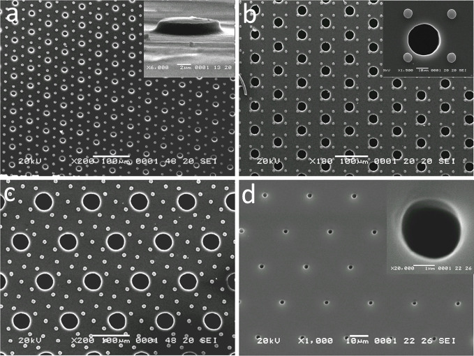
The NeuroArray was fabricated by one-take molding from a SU-8 mold fabricated using conventional soft-lithography techniques17,18. The fabrication and patterning of microscale through-holes in PDMS membrane for biological assays has always been challenging. Several approaches have previously been reported, though each of them has its drawbacks that limited their wide application. One of the simplest is to manually punch through a thin layer of PDMS using biopsy tools, which is very imprecise and time-consuming19. Folch et al used a high-pressure assisted compression20, however, this method often fails to produce through-holes due to the formation of a very thin layer of residual PMDS membrane over the mold; and the high pressure applied against the SU-8 mold can easily damage delicate microscale features on silicon wafers. Even though the excess PDMS can be blew away before the PDMS curing21, this method causes imperfection in the flatness of resulted stencil device and is limited to features greater than 50 µm. Recently, Chen et al utilized plasma etching (RIE) to successfully engrave different through-structures in PDMS22, but this method requires expensive equipments and extensive fabrication experiences. In this study, we developed a novel and straightforward fabrication process, by introducing a removable sacrificial layer on top of the photoresist features. The general procedures of this method were illustrated in Fig. 1c. Specifically, a PDMS blanket (500 µm thick) was used to protect the top of photoresist features from contacting PDMS pre-polymer during the whole curing process. All surfaces of the PDMS blanket were treated with silane, which ensured the easy removal of the protection blanket after PDMS curing, leaving behind a PMDS membrane containing various through-hole structures. As shown in Fig. 2, our method guaranteed perfect-flat top of produced stencils: no concaved features around each hole as reported previously21, and we can achieve through-holes in PDMS with feature sizes down to 3 µm (Fig. 2d). Importantly, this method requires no special equipment and can be easily adopted in any lab with regular PDMS fabrication capability.
Figure 2. Characterization of NeuroArray stencil fabricated using sacrificial-layer-protected PDMS molding.
SEM images of NeuroArray stencil with different through-hole diameters: (a) 10 µm, (b) 30 µm, (c) 50 µm. Inset in panel a) shows the scale and height of supporting micropillars, which provide space for neurites growth between glass substrate and stencil membrane. Inset in panel b) shows an enlarged view of a 30 µm through-hole surrounded by supporting micropillars. (d) A PMDS stencil with 3 µm through-holes, the inset shows an enlarged view of a single 3 µm through-hole.
Culture neuron in NeuroArray
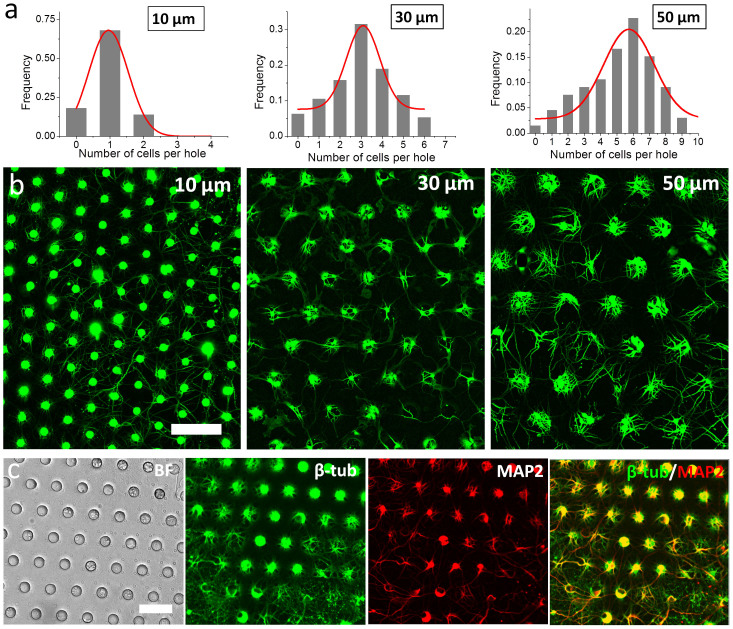
To use the NeuroArray for primary neuron culture, a PDMS stencil with supporting micropillars was assembled with a culture well to assume a transwell configuration, which was placed directly onto regular glass substrates coated with plolylysine and laminin. Neurons were seeded and settled into the through-holes with a brief centrifugation. The seeding density was fixed at 30–50 k/cm2, which resulted in one or multiple neuron cells in each hole, depending on its diameter. Three different types of NeuroArrays with holes of different diameters, 10 µm, 30 µm and 50 µm, were tested in this study. More than 80% through-holes were filled with cells in all three conditions (Fig. 3a). For most 10 µm holes, only single cell can fit in it, given the size matching between the holes and neuron somata. For 30 µm and 50 µm holes, the number of cells in each hole roughly showed a normal distribution centered at three or six cells per hole respectively, as shown in Fig. 3a. As the scale and morphology of a neural network both play important roles in its function23, the capability to manipulate the number of cells in each through-hole enables us to scale up a neural network without changing its morphology by including more cells in each functional units, and therefore provides one more dimension of flexibility to study and utilize the computational dynamics of neural networks.
Figure 3. Culture of hippocampal neuron in NeuroArray.
(a) Distribution of neuron cells in NeuroArray with through-holes of different diameters. (b) Florescence images of βIII-tubulin showing the growth of neuron cells in NeuroArrays for 6 days. (c) Characterization of long-term neuron culture (18DIV) in NeuroArray of 30 µm through-holes. Cells were stained for βIII-tubulin (green) and MAP2 (red). Scale bar, 100 µm.
The 3D structure of our NeuroArray enabled immobilization and patterning of neuron somata in array format, while allowing all neurites to freely grow in the space between the PDMS membrane and glass substrates, which was provided by the supporting micropillars. Hippocampal neurons exhibited similar growth patterns as they did on plain glass substrates. After one week in culture, axons and dendrites were properly developed to form well connected, highly organized networks, as indicated by immunostaining of neuron-specific markers, Tau-1 and MAP2 (Fig. 3), and cultures can be well maintained for more than 3 weeks in the NeuroArray.
Functional analysis of the dynamic activity of neural network in NeuroArray
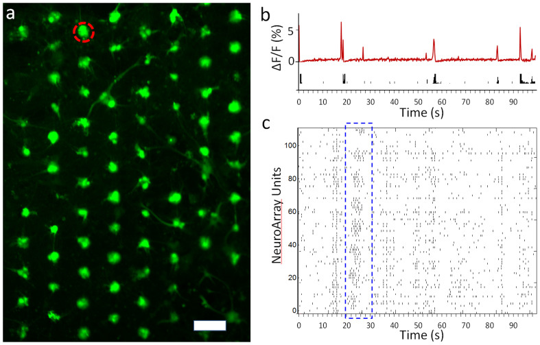
The array format of neurons in a well-patterned network could facilitate automated tracking, recording and manipulation of neural activity from every single cell, or functional unit (couple cells in each through-hole) in a NeuroArray. Here, we combined optical microscopy of neuronal activities, namely calcium imaging, with the NeuroArray to demonstrate the capability to infer and decipher the functional dynamics of a morphologically determined neural network (Supplementary Movie S1). As shown in Fig. 4, calcium fluctuation signals from all functional units can be automatically acquired and analyzed with simple image processing software, and the spiking activities in these neurons could be inferred in real-time from fluorescence traces using a fast nonnegative deconvolution algorithms24. Fig. 4c showed a hexagonal neural network with repeating synchronized spiking activity across the whole network of more than 100 units, which could be an analogy to the orchestrated activation of neural cell assemblies in vivo25,26. Potentially, this technique can be applied to monitor the dynamic changes and remodeling of a neuronal network in response to external stimulations, such as electrical stimulation or drug treatment.
Figure 4. Optical recording of spontaneous activities in neural network formed in NeuroArray.
(a) Fluorescence image showing arrays of neurons loaded with fluo-4 in NeuroArray. Scale bar, 100 µm. (b) Calcium fluctuation and inferred spike trains of a functional unit circled in panel a). (c) A temporal raster plot of the activities in each unit of neuronal network in a neural assembly of more than 100 functional units (through-holes with neuron cells). One of the synchronized network spiking was outlined in blue box.
Designed neural network using NeuroArray
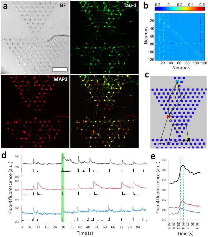
The right connectivity matrix enables neural circuits to perform difficult calculations on surprisingly short timescales and with little error3. The goal to implement such computational power to create live “chip” has encouraged investigations to design and create patterned neuronal devices or interface in vitro. Ideally, our NeuroArray can accommodate different network topology by configuring pre-designed array format of through-holes, which could subsequently be used to assemble living neural networks with the capability to control signal transmission mode within them. As shown in Fig. 5a, we demonstrated reliable patterning of series of triangle networks. The spiking data of these networks could be further processed to derive the connectivity matrix among neurons in different through-holes, so that functional topology of a well-defined network can be determined (Fig. 5b, c). When different regions were defined as “input” and “output” units, the asymmetric network topology enabled directional propagation of spiking activity from “input” to “output” regions, indicating a neuronal “diode” function (Fig. 5d). A single spike showed about 200 milliseconds delay across a whole triangle assembly, as indicated by the three functionally connected units as indicated in Fig. 5e. Thus, our NeuroArray technique provided an easy approach to design arbitrary neural network, and can be readily used to create live neuronal devices based on cultured networks of different topologies8.
Figure 5. Patterned neural network assembly with a “diode” topology.
(a) Images showing the growth of neurons in a “diode” NeuroArray with series of triangle patterns. 5DIV neurons were fluorescent stained for Tau-1 (green) and MAP2 (red). Scale bar, 200 µm. (b) Connectivity matrix for a “diode” neural network with 120 functional units. (c) Illustrative diagram partially showing connections between different elements in a “diode” neural network. (d) Traces of calcium fluctuation of three neurons (color-coded in panel (c)) showing their spiking activities. (e) Details of fluorescent traces for the time window indicated by green box in panel (d).
Discussion
The human brain has a unique and dramatic complexity within a highly integrated architecture. Understanding and evaluation of brain function in normal or diseased conditions, and fully taking advantage of its computational power require systematic approach to study the macroscale activity of neuron assemblies, as well as cellular method to study the microscale function with single neuron addressability. Recreation of neural network in vitro with designed topology is therefore a valuable tool for decipher how neurons behave when interacting in hierarchical networks. In this study, we developed a simple and effectively platform to pattern primary neurons in arbitrary array format for long-term interrogation of neural circuitry with single cell resolution. Unlike many surface-chemistry-based patterning methods, the NeuroArray technique is specially designed to accommodate neuron's polarized morphologies to make arrays of cells without restricting their neurite growth, and thus enable the formation of well-connected, spontaneously active neural network, in which the spiking activities may be analogous in some way to pulses that propagate in the human brain26.
The NeuroArray device was based on a silicone stencil, which was made using a novel fabrication method that employs a removable sacrificial layer during PDMS molding process. This simple method could effectively guarantee the production of almost 100% through-structures in a thin layer of PDMS with feature sizes down to 3 µm, which has been very challenging for previous methods such as the commonly used high-pressure assisted molding6, and is comparable to results demonstrated using expensive etching equipments22. Such simple fabrication protocol will ensure easy transfer of this method to any laboratories with basic PDMS fabrication capability. Another major merit of the NeuroArray is the capability to accommodate neuronal network with various geometries by arbitrarily composing the array elements, and also to manipulate the network scale by tuning the size of through-holes. This simple and novel patterning scheme provides new possibility and flexibility to facilitate studies and applications of computational devices based on live neuron cultures8. As we have demonstrated in this study, the NeuroArray is well compatible with optical microscopy for long term tracking and recording of specific neurons, which enabled the capture of directional signal transmission in a live diode-like neural network. Essentially, the NeuroArray is a universal patterning platform designed for, but not limited to neuron cells. With little adaption, it can be readily interfaced with other interrogation modalities, such as the widely used multi-electrode array (MEA) system and droplet-based delivery technique, for high-throughput drug testing27,28, or for building neuron culture based live logic devices with designed inputs and outputs for computational applications.
Methods
NeuroArray fabrication
The NeuroArray was made by assembling a standard coverslip, a PDMS stencil and a culture well. The PDMS stencil was replica molded from a silicon mold with microscale patterns, which was consisted of two SU-8 (Microchem) layers on a silicon wafer. The first layer contained negative features of the supporting micropillars (3 µm). The second layer of SU-8 contained features for the through-holes (10–60 µm in height). The two layers of photoresist were patterned sequentially using standard photo-lithography with alignment markers. To create the through-structures fabrication, a thin layer of silane-treated (trichloro-perfluorooctyl silane, Sigma) PDMS blanket was placed on SU-8 features to prevent the top from contacting prepolymer of PDMS. The prepolymer was then poured onto the mold and degassed before a plastic transparency being carefully lowered onto the prepolymer. The stack containing mold, protection layer, prepolymer, and transparency was clamped wihtin two flat aluminum plates. The whole setup was baked at 80°C for 12 hours, and the protection layer (sacrificial layer) was removed before releasing the stencil (10–60 µm thick) from the mold.
Cell culture
All procedures involving animals were approved by the animal ethical committee of City University of Hong Kong. Hippocampal neuron cultures were prepared following the method previously described29. Briefly, hippocampal neurons were cultured on 12 mm Germen coverslips (Bellco Glass). Before using, the coverslips were cleaned with concentrated nitric acid (70% wt/wt) overnight and rinsed with sterile DI water. The coverslips were further coated with polylysine (Sigma) at 100 μg/ml overnight and then laminin at 10 μg/ml (Invitrogen) for 4 hours before seeding neuron cells. Hippocampi tissue were dissected from E18 Sprague Dawley rats, and treated with papain (Sigma) for 30 min at 37°C. Dissociated neurons were prepared by triturating enzymatic treated tissue with a 1 ml pipette tip in DMEM solution contain 10% FBS. Neurons were then seeded onto coated coverslips assembled with NeuroArray at a density of 3–5 × 10⁴/cm2. The loaded NeuroArray was placed in a petri-dish, which was placed in a centrifuge (Sorvall ST 16R, Thermo Scientific) with a microplate swinging bucket rotor (M-20, Thermo Scientific), and spun at 200 rpm (8 g) for 1 minute. After initial adhesion of neuron cells (2 hours after seeding), the medium was replaced by Neurobasal medium supplemented with B27, L-glutamine and penicillin/streptomycin, and extra cells were flushed away. Half of the medium was replaced with fresh medium every 3–4 days.
Immunocytochemistry
For analysis, cells were fixed for 30 min in 4% paraformaldehyde in phosphate-buffered saline (PBS), permeablized in 0.25% Triton X-100 for 15 min, and then blocked with 4% BSA in PBS for 2 hours at room temperature or overnight at 4°C. Cultures were incubated with primary antibodies in 4% BSA for 2 hours at room temperature, rinsed with PBS, incubated with secondary antibodies for 1 hour, and were again rinsed with PBS. Cell nucleus were also stained with 4′,6-diamidino-2-phenylindole (DAPI) before imaging. The primary antibodies included mouse anti-Tau1 (Millipore), rabbit anti-MAP2 (Millipore).
Calcium Imaging and analysis
For calcium imaging, neuron cultures in NeuroArray were incubated with the calcium-sensitive dye Fluo-4 AM ester (2 μM, Life Technology) at 37°C for 60 min in artificial cerebrospinal fluid (ACSF) solution, and then rinsed three times for 5 min with fresh ACSF solution. The ACSF solution contained 126 mM NaCl, 3 mM KCl, 26 mM NaHCO3, 1 mM NaH2PO4, 2 mM CaCl2, 1 mM MgSO4, 10 mM dextrose. After rinsing, the sample was placed into the recording chamber mounted on the stage of an inverted microscope (IX81, Olympus). Live cell imaging was performed to assess the dynamics of Ca2+ signals inside neuron cells within arrays of through-holes. Time-lapse recording was conducted with an interval of 50 ms and an exposure of 50 ms, which allowed a frame rate of 10 frames/sec. To analyze the calcium imaging results, the fluorescence change over time was defined as ΔF/F0 = (F1-F0)/F0, where F1 indicated the fluorescence intensity of a current frame and F0 indicated the fluorescence intensity of the previous frame. A fast nonnegative deconvolution method was used for spike train inference from population calcium imaging24.
Author Contributions
P.S. conceived the project and wrote the manuscript. W.L., Z.X., J.H., X.L. and P.S. conducted the experiments and analyzed the data. R.L. and C.H.C. also contributed to the data analysis and writing of the manuscript.
Supplementary Material
Calcium Imaging of Neural Network in NeuroArray
Acknowledgments
This work was supported by the University Grants Council (ECS125012), National Science Foundation of China (81201164) and grants from the City University of Hong Kong (7200269, 9610215, 9667077, 7003022). We thank the logistic support from the Shenzhen Key Laboratory Funding Scheme of Shenzhen Municipal Government.
References
- Hua J. Y. Y. & Smith S. J. Neural activity and the dynamics of central nervous system development. Nature Neuroscience 7, 327–332 (2004). [DOI] [PubMed] [Google Scholar]
- Palop J. J., Chin J. & Mucke L. A network dysfunction perspective on neurodegenerative diseases. Nature 443, 768–773 (2006). [DOI] [PubMed] [Google Scholar]
- Shahaf G. & Marom S. Learning in networks of cortical neurons. J Neurosci 21, 8782–8788 (2001). [DOI] [PMC free article] [PubMed] [Google Scholar]
- Dertinger S. K., Jiang X., Li Z., Murthy V. N. & Whitesides G. M. Gradients of substrate-bound laminin orient axonal specification of neurons. Proc Natl Acad Sci U S A 99, 12542–12547 (2002). [DOI] [PMC free article] [PubMed] [Google Scholar]
- Martin K. C. et al. Synapse-specific, long-term facilitation of aplysia sensory to motor synapses: a function for local protein synthesis in memory storage. Cell 91, 927–938 (1997). [DOI] [PubMed] [Google Scholar]
- Shi P. et al. Synapse microarray identification of small molecules that enhance synaptogenesis. Nat Commun 2, 510 (2011). [DOI] [PMC free article] [PubMed] [Google Scholar]
- Jain S. & Heutink P. From single genes to gene networks: high-throughput-high-content screening for neurological disease. Neuron 68, 207–217 (2010). [DOI] [PubMed] [Google Scholar]
- Feinerman O., Rotem A. & Moses E. Reliable neuronal logic devices from patterned hippocampal cultures. Nature Physics 4, 967–973 (2008). [Google Scholar]
- Kleinfeld D., Kahler K. H. & Hockberger P. E. Controlled outgrowth of dissociated neurons on patterned substrates. J Neurosci 8, 4098–4120 (1988). [DOI] [PMC free article] [PubMed] [Google Scholar]
- Branch D. W., Wheeler B. C., Brewer G. J. & Leckband D. E. Long-term maintenance of patterns of hippocampal pyramidal cells on substrates of polyethylene glycol and microstamped polylysine. IEEE Trans Biomed Eng 47, 290–300 (2000). [DOI] [PubMed] [Google Scholar]
- Kam L., Shain W., Turner J. N. & Bizios R. Axonal outgrowth of hippocampal neurons on micro-scale networks of polylysine-conjugated laminin. Biomaterials 22, 1049–1054 (2001). [DOI] [PubMed] [Google Scholar]
- Shi P., Shen K. & Kam L. C. Local presentation of L1 and N-cadherin in multicomponent, microscale patterns differentially direct neuron function in vitro. Dev Neurobiol 67, 1765–1776 (2007). [DOI] [PubMed] [Google Scholar]
- Shi P., Nedelec S., Wichterle H. & Kam L. C. Combined microfluidics/protein patterning platform for pharmacological interrogation of axon pathfinding. Lab Chip 10, 1005–1010 (2010). [DOI] [PMC free article] [PubMed] [Google Scholar]
- Taylor A. M. et al. A microfluidic culture platform for CNS axonal injury, regeneration and transport. Nat Methods 2, 599–605 (2005). [DOI] [PMC free article] [PubMed] [Google Scholar]
- Dworak B. J. & Wheeler B. C. Novel MEA platform with PDMS microtunnels enables the detection of action potential propagation from isolated axons in culture. Lab Chip 9, 404–410 (2009). [DOI] [PMC free article] [PubMed] [Google Scholar]
- Wheeler B. C. & Brewer G. J. Designing Neural Networks in Culture: Experiments are described for controlled growth, of nerve cells taken from rats, in predesigned geometrical patterns on laboratory culture dishes. Proc IEEE Inst Electr Electron Eng 98, 398–406 (2010). [DOI] [PMC free article] [PubMed] [Google Scholar]
- Qin D., Xia Y. & Whitesides G. M. Soft lithography for micro- and nanoscale patterning. Nat Protoc 5, 491–502 (2010). [DOI] [PubMed] [Google Scholar]
- Whitesides G. M., Ostuni E., Takayama S., Jiang X. & Ingber D. E. Soft lithography in biology and biochemistry. Annu Rev Biomed Eng 3, 335–373 (2001). [DOI] [PubMed] [Google Scholar]
- Heo Y. S. et al. Characterization and resolution of evaporation-mediated osmolality shifts that constrain microfluidic cell culture in poly(dimethylsiloxane) devices. Anal Chem 79, 1126–1134 (2007). [DOI] [PMC free article] [PubMed] [Google Scholar]
- Folch A., Jo B. H., Hurtado O., Beebe D. J. & Toner M. Microfabricated elastomeric stencils for micropatterning cell cultures. J Biomed Mater Res 52, 346–353 (2000). [DOI] [PubMed] [Google Scholar]
- Choi J. H., Lee H., Jin H. K., Bae J. S. & Kim G. M. Micropatterning of neural stem cells and Purkinje neurons using a polydimethylsiloxane (PDMS) stencil. Lab Chip 12, 5045–5050 (2012). [DOI] [PubMed] [Google Scholar]
- Chen W., Lam R. H. & Fu J. Photolithographic surface micromachining of polydimethylsiloxane (PDMS). Lab Chip 12, 391–395 (2012). [DOI] [PMC free article] [PubMed] [Google Scholar]
- Buzsaki G., Logothetis N. & Singer W. Scaling brain size, keeping timing: evolutionary preservation of brain rhythms. Neuron 80, 751–764 (2013). [DOI] [PMC free article] [PubMed] [Google Scholar]
- Vogelstein J. T. et al. Fast nonnegative deconvolution for spike train inference from population calcium imaging. J Neurophysiol 104, 3691–3704 (2010). [DOI] [PMC free article] [PubMed] [Google Scholar]
- Ohki K., Chung S., Ch'ng Y. H., Kara P. & Reid R. C. Functional imaging with cellular resolution reveals precise micro-architecture in visual cortex. Nature 433, 597–603 (2005). [DOI] [PubMed] [Google Scholar]
- Eytan D. & Marom S. Dynamics and effective topology underlying synchronization in networks of cortical neurons. J Neurosci 26, 8465–8476 (2006). [DOI] [PMC free article] [PubMed] [Google Scholar]
- Kang G., Lee J. H., Lee C. S. & Nam Y. Agarose microwell based neuronal micro-circuit arrays on microelectrode arrays for high throughput drug testing. Lab Chip 9, 3236–3242 (2009). [DOI] [PubMed] [Google Scholar]
- Luo R. C., Ranjan S., Zhang Y. & Chen C. H. Near-infrared photothermal activation of microgels incorporating polypyrrole nanotransducers through droplet microfluidics. Chem Commun 49, 7887–7889 (2013). [DOI] [PubMed] [Google Scholar]
- Kaech S. & Banker G. Culturing hippocampal neurons. Nat Protoc 1, 2406–2415 (2006). [DOI] [PubMed] [Google Scholar]
Associated Data
This section collects any data citations, data availability statements, or supplementary materials included in this article.
Supplementary Materials
Calcium Imaging of Neural Network in NeuroArray


