Abstract
A single multimode fiber has been considered an ideal optical element for endoscopic imaging due to the possibility of the direct image transmission via multiple spatial modes. However, the wave distortion induced by the mode dispersion has been a fundamental limitation. In this Letter, we proposed a method for eliminating the effect of the mode dispersion and therefore realized wide-field endoscopic imaging by using only a single multimode fiber with no scanner attached to the fiber. Our method will potentially revolutionize endoscopy in various fields encompassing medicine and industry.
Since the invention of a rigid type endoscope, the endoscopy has become a widely used tool for industrial, military and medical purposes due to its ability to visualize otherwise inaccessible structures. In the history of the technological developments, the advent of an optical fiber has set an important turning point. Especially, a multimode optical fiber has drawn interest because numerous independent spatial modes can be used for parallel information transport. However the single multimode fiber could not be used in itself for the imaging purpose. When light wave couples to and propagates through the fiber, the wave is distorted into a complex pattern due to the mode dispersion [1]. Moreover, it has been much more challenging to use a single multimode fiber for the practical endoscopic imaging in which the imaging operation should be performed in the reflection mode. In such case, light wave injected into the fiber is distorted twice, i.e. on the way in for the illumination and on the way out for the detection. For this reason, a fiber bundle [2–4] has been widely used and thus became a standard for the commercial endoscopes. In this so-called fiber scope, each fiber constituting the bundle acts as a single pixel of an image, and the number of fibers in the bundle determines the pixel resolution. Therefore the requirement for a large number of fibers for high resolution imaging has posed constraints on the diameter of the endoscope, thereby causing considerable limitation on the accessibility of the device.
The use of a multimode fiber for the endoscopic purpose can have a clear advantage over the fiber bundle in terms of the diameter of imaging unit. If the numerous individual optical fibers in the bundle are replaced with multiple propagating modes of a single fiber, the diameter of the imaging unit can be significantly reduced. The pixel density, which is the number of modes per unit area in this case, of a multimode fiber is given approximately by ρ ~ 16/π(NA/λ)2, where NA is the numerical aperture of the fiber and λ the wavelength of the light source [1]. For NA = 0.5 each pixel occupies an area of about λ2. By contrast, each fiber in a fiber bundle has a typical area of ~ 50 − 100λ2. Therefore the pixel density can be greater by 1–2 orders of magnitude than that possible with a fiber bundle.
In order to exploit this benefit of a multimode fiber, a number of ways were proposed to handle the image distortion. For example, the object images were encoded in the spectral, spatial and wavelength-time content and the transmitted waves were decoded to recover the original image information [5, 6]. Optical phase conjugation was used to deliver image information in double-path configuration [7, 8] and to generate a focused spot [9]. However, both approaches are not suitable for endoscopic purpose in which an object image should be retrieved at the reflection mode of detection. Indeed, none of the previous studies could achieve the wide-field endoscopic imaging by a single multimode fiber to date.
We note that the concept of the recent studies enabling a disordered medium to be used as an imaging optics can be extended to achieve the reflection mode of imaging. In these studies, the so-called transmission matrix, which describes the input-output response of an arbitrary optical system by connecting the free modes at the input plane to those at the output plane, of an unknown complex medium was used for the delivery of an image through the medium [10–12] and for the control of the light field at the opposite side of the disordered medium [13, 14]. In fact, a multimode optical fiber can also be considered as a complex medium because bending and twist of the fiber complicate wave propagation through the fiber. Čižmár et al. demonstrated that a wavefront shaping technique in conjunction with the knowledge of a transmission matrix can shape the intensity pattern at the far side of the fiber [15]. But so far, the transmission matrix approach itself was used only for the transmission mode of imaging.
In this Letter, we made use of the measured transmission matrix of a multimode optical fiber to reverse the on-the-way-out distortion of the detected light. By employing the speckle imaging method the on-the-way-in distortion was also eliminated. In doing so, we converted the multimode fiber into a self-contained 3D imaging device that doesn’t require a scanner or a lens. We demonstrated the first wide-field endoscopic imaging by using a single multimode fiber at relatively high speed (1 frame/s for 3D imaging) with a high spatial resolution (1.8 µm). The diameter of the endoscope is then reduced to the fundamental limit - the diameter of a single fiber (230 µm in diameter). We call this method lensless microendoscopy by a single fiber (LMSF). As a proof-of-concept study, we performed 3D imaging of a biological tissue from a rat intestine using LMSF.
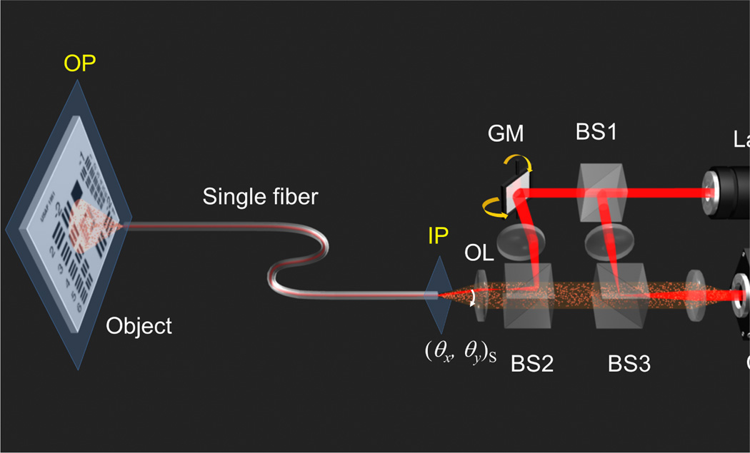
Our experimental setup is shown in Fig. 1 (for more details, see Supplemental material). A He-Ne laser with a wavelength of 633 nm is split into two by a beam splitter (BS1) and the transmitted beam is reflected off by a 2-axis galvanometer scanning mirror (GM). After being reflected at a second beam splitter (BS2), the beam illuminates at the input plane (IP) of the fiber, couples to the fiber and subsequently propagates toward the object plane (OP) located at the exit of the fiber to illuminate a target object. The OP is determined to be the conjugate plane to the pivot point of the GM used for recording the transmission matrix (Fig. S1(b)). Here we use a 1 meter-long multimode optical fiber with 200 µm core diameter, 15 µm clad thickness (230 µm in total diameter) and 0.48 NA. For a test object we used either a USAF target or a biological tissue. The light reflected from the object is collected by the same optical fiber. The collected light by the fiber is guided back through the fiber to the IP, and the output image is then delivered through the beam splitters (BS2 and BS3) into the camera. The laser beam reflected by BS1 is combined with the beam from the fiber to form an interference image at the camera. Using an off-axis digital holography algorithm, both amplitude and phase of the image from the fiber are retrieved [16, 17].
FIG. 1. Experimental scheme of LMSF.
The setup is based on an interferometric phase microscope. The interference between the reflected light from the object located at the opposite side of a single multimode fiber and the reference light is recorded by a camera. A 2-axis galvanometer scanning mirror (GM) controls the incident angle (θx, θy)S to the fiber. BS1, BS2 and BS3: beam splitters. OL: objective lens. IP: input plane of a multimode optical fiber (0.48 NA, 200 µm core diameter). OP: object plane.
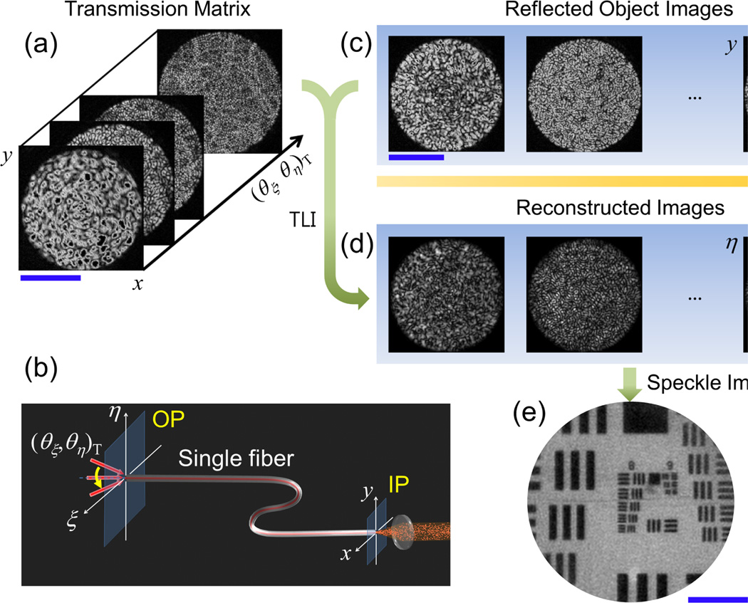
The recorded images of the USAF target at the camera are shown in Fig. 2(c). Two processes mask the object information: (1) distortion of illumination light on the way in (IP→OP) and (2) the scrambling of the light reflected by the object on the way out (OP→IP). In order to overcome these two distortions, we employ methods of speckle imaging [18–20] and the turbid lens imaging (TLI) [11], respectively.
FIG. 2. Image reconstruction process.
(a) Representative images of a measured transmission matrix following the scheme shown in (b). (b) Scheme of a separate setup from Fig. 1 for measuring a transmission matrix of the single fiber from OP to IP. Incident angle (θx, θy)T is scanned and the transmitted images are recorded. (c) Reflected object images taken by the setup shown in Fig. 1 at different illumination angles (θx, θy)S. (d) Reconstructed object images after applying TLI method on the images in (c). Image scale is the same as that of (c). (e) Averaging of all reconstructed images in (d). Scale bars indicate 100 µm in (a), (c) and 50 µm in (e) respectively.
First we describe the application of TLI for unscrambling the distortion for the object image. As shown in Fig. 2(b), we first characterize the input-output response of the optical fiber from the object side to the camera side (OP→IP). We scan the incident wave in its angle (θζ, θη)T to the fiber and record its transmitted image at the camera. A set of these angle-dependent transmission images is called the transmission matrix T [10, 11, 14]. We measure the transmission matrix elements up to 0.22 NA by recording 15,000 images at 500 frames/s. This characterization for the fiber transmission is performed just in 30 seconds. Since this characterization is performed prior to recording the reflected images of the sample, it is not included in the actual image acquisition process. Figure 2(a) shows a few representative measured transmission matrix elements of the multimode fiber. Here only the amplitude images are shown due to the space limit, but the corresponding phase information is simultaneously recorded (Supplemental Fig. S2). The transmitted patterns are random speckles and the average size of the speckle decreases as we increase the angle of illumination. This is because high angle of illumination mostly couples to the high order modes of the fiber.
Once the transmission matrix is recorded, we can reconstruct an object image at the OP from the distorted image recorded at the IP (each image in Fig. 2(c)) by using the TLI method (For the details of the algorithm, see Supplemental material). The process is an inversion of the transmission matrix given by the relation
| (1) |
Here EIP and T−1 represent the recorded image at the IP and the inversion of the measured transmission matrix, respectively, and EOP is the image at the OP. Using Eq. (1), the distortion from OP to IP is reversed. The recovered images at the OP are shown in Fig. 2(d). The reconstructed images remain devoid of object structure because the illumination light is distorted due to the propagation of the illumination from IP to OP.
Next, we deal with this distortion of the illumination light at the OP by using the speckle imaging method. We scan the illumination angle, (θ x, θy)S, at the IP as shown in Fig. 1. The change in the illumination angle causes the variation of the illumination light at the target object; in other words, different speckle field is generated as we vary the angle (θx, θy)S. According to the speckle imaging method, a clean object image can be acquired if we average sufficient numbers of images recorded at different speckle illuminations [19]. Then the complex speckle illumination patterns are averaged out, leaving a clean object image. In order to implement this, we record multiple object images, typically at 500 different illumination angles, (θx, θy)S. This procedure takes 1 second, which is the actual image acquisition time of our LMSF. Since the frame rate of the camera is the major factor for determining the image acquisition time, the use of a higher speed camera will significantly reduce the data acquisition time. The representative multiple recorded images are shown in Fig. 2(c). Then the TLI method is applied to each of them in order to obtain corresponding object images at the OP (each in Fig. 2(d)). Here each image contains object information even though they all look dissimilar due to the different speckle pattern of illumination. By adding all the intensity images in Fig. 2(d), we obtain a clear image of the object as shown in Fig. 2(e). The image processing for 500 raw images takes about 30 seconds when a personal computer with Intel Core i5 CPU is used. Therefore the combination of speckle imaging and TLI methods enables a single fiber microendoscopic imaging.
LMSF presents spatial resolution equivalent to the incoherent imaging due to the speckle illumination, which is twice better than the coherent imaging. The effective NA is extended up to twice of that covered by the transmission matrix. In our LMSF, transmission matrix is measured up to 0.22 NA, so that the diffraction limit of the imaging is about 1.8 µm. In Fig. 2(e), the structures in group 8 of the USAF target whose smallest element has a peak-to-peak distance of 2.2 µm are resolved. The field of view is about the same as the 200 µm diameter of the fiber core.
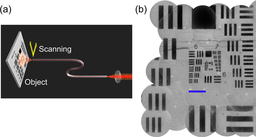
In conventional diagnostic endoscopy, medical practitioners control the object end of an endoscope to image tissues within the body. Although our method does not support this fully flexible endoscopic operation due to the variation of transmission matrix induced by the bending of the fiber, we found that the endoscopic operation is attainable up to a partially flexible degree. In order to demonstrate the flexible endoscopic operation in LMSF, we translated the end of the fiber facing a sample (Fig. 3(a)). We measured the transmission matrix of the fiber at an initial position of the fiber end and then used the same matrix to reconstruct object images taken while moving the fiber end. For each position, we acquired 500 distorted object images and use the recorded transmission matrix to reconstruct the original object image. Figure 3(b) shows the composite image of the USAF target in which multiple images are stitched together. Each constituting image has a view field of about 200 µm in diameter and the translation ranges of the fiber end are about 800 µm in horizontal and about 1000 µm in vertical directions. Structures ranging in a wide area are all clearly visible. Although bending induced by the movement of the fiber causes the change of the transmission matrix, many of the matrix elements stay intact and contribute to the image reconstruction. According to our experiment the LMSF is working well up to a centimeter-travel of the fiber end, confirming that our LMSF has partial flexibility for searching for the view field (Supplemental Fig. S3).
FIG. 3. Scanning of the fiber end to enlarge the view field.
(a) The fiber end at the object side is translated to take images at different part of the target object. The object images taken at different sites are reconstructed with the same transmission matrix measured at the initial position of the fiber. (b) Reconstructed images are stitched to enlarge the field of view. Scale bar indicates 100 µm.
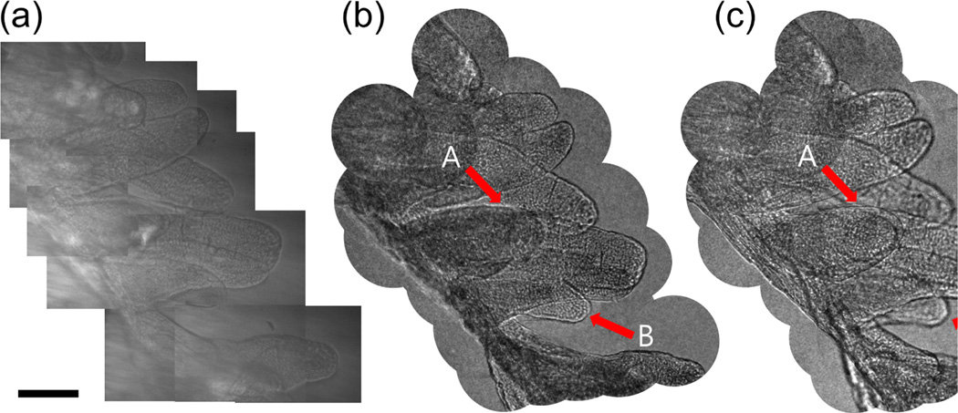
To demonstrate the potential of LMSF as an endoscope to image biological tissue, we imaged a sample of rat intestine tissue. We loaded the tissue at the OP and scanned the fiber end to extend the view field as done in Fig. 3(a). Figure 4(b) is the composite image taken by the LMSF for the site where multiple villi are seen. The villi are clearly visible with their external features in excellent agreement with the conventional bright field image taken by transmission geometry (Fig. 4(a)). In fact, the contrast of LMSF image is better than that of the bright field image. This is because the absorption by the villus is weak for the transmission mode imaging while the reflection at the rough surface provides relatively strong contrast for the LMSF imaging.
FIG. 4. Image of villus in a rat intestine tissue taken by LMSF.
(a) A composite image made by several bright field images taken by conventional microscope in the transmission geometry. (b) A composite image made by several LMSF images at the same site. Scale bar, 100 µm. (c) The same image as (b), but after numerical refocusing by 40 µm toward the fiber end. The arrows indicated by A point to the villus in focus at (c) while those indicated by B refer to the villus in focus at (b).
The LMSF can capture the 3D map of biological tissue without depth-scanning of the fiber end. As shown in Eq. (1), we acquire complex field maps, EOP(ζ, η), of a specimen which contain both amplitude and phase of the reflected waves. Once the complex field is known, one can numerically solve wave propagation to a different depth [21] (see Supplemental material). This enables numerical refocusing of an acquired image to an arbitrary depth. Figure 4(c) is the result of numerical refocusing from the original image (Fig. 4(b)) by 40 µm toward the fiber end. The villus indicated by A that used to be blurred in Fig. 4(b) comes to a focus and its boundary becomes sharp. On the other hand, the villus pointed by B gets blurred due to the defocusing. By comparing Figs. 4(b) and 4(c), we can clearly distinguish relative depths of multiple villi in the view field. This 3D imaging ability of LMSF will eliminate the need for the physical depth-scanning such that it will dramatically enhance the speed of volumetric imaging.
In conclusion, we have demonstrated partially flexible wide-field endoscopic imaging with a single multimode optical fiber without a lens or any scanning element attached to the fiber. After characterizing the transmission property of the optical fiber, unique imaging methods of TLI and speckle imaging were used to see an object through a curved optical fiber in the reflection configuration. The image acquisition time was 1 second for the 3D imaging with 12,300 effective image pixels, and the view-field was given by the core diameter of the fiber. The pixel density of LMSF is about 30 times greater than that of a typical fiber bundle (10 µm diameter for each pixel), and can be increased further if full NA transmission matrix is measured.
The proposed method is applicable only for partially flexible endoscopic operation since significant bending of the fiber modifies the transmission matrix. However, LMSF will still find many new possibilities in various fields, especially in the biomedical field. In particular it can replace the rigid type endoscopes which are widely used in the medical practices to explore and biopsy the abdomen, urinary bladder, nose, ears and thorax. Since LMSF can miniaturize the rigid type endoscope to its fundamental limit - the diameter of the optical fiber, the accessibility of the endoscope to the target object can be significantly improved. In addition, our technique can be implemented in a needle biopsy [22, 23] in such a way that a single multimode fiber is inserted through a fine needle. By imaging a tissue faced in front of the fiber, an in situ diagnosis will be made possible.
Our approach is fundamentally different from other single fiber endoscopy techniques [24] such as confocal endoscopy [25, 26], optical coherence tomography based endoscopy [23, 27], and spectrally encoded endoscopy [28]. In these techniques, a single-mode fiber is used to generate a spot at the object and the spot is scanned for image acquisition. Therefore, minimum achievable diameter of the endoscope is mainly limited by the scanning unit, which is typically larger than the fiber diameter. In comparison with a recent study in which a single multimode optical fiber is used for the image acquisition by a point scanning method [29, 30], our method of wide-field imaging is advantageous in the image acquisition speed and the pixel resolution. As such, the proposed method will find its unique applications in the biomedical field and contribute to greatly improving the ability to find fatal diseases in particular.
Supplementary Material
Acknowledgments
The authors thank Dr. Euiheon Chung for helpful discussion. This research was supported by Basic Science Research Program through National Research Foundation of Korea (NRF) funded by the Ministry of Education, Science and Technology (grant number: 2010-0011286 and 2011-0016568), KOSEF (project: R1202991), and also by the National Institutes of Biomedical Imaging and Bioengineering (9P41-EB015871-26A1).
References
- 1.Saleh BEA, Teich MC. Fundamentals of photonics. 2nd ed. John Wiley & Sons; 2007. [Google Scholar]
- 2.Hopkins HH, Kapany NS. Nature. 1954;173:39. [Google Scholar]
- 3.Koenig F, Knittel J, Stepp H. Science. 2001;292:1401. doi: 10.1126/science.292.5520.1401. [DOI] [PubMed] [Google Scholar]
- 4.Flusberg BA, et al. Nat. Methods. 2005;2:941. doi: 10.1038/nmeth820. [DOI] [PMC free article] [PubMed] [Google Scholar]
- 5.Friesem AA, Levy U. Opt. Lett. 1978;2:133. doi: 10.1364/ol.2.000133. [DOI] [PubMed] [Google Scholar]
- 6.Tai AM, Friesem AA. Opt. Lett. 1983;8:57. doi: 10.1364/ol.8.000057. [DOI] [PubMed] [Google Scholar]
- 7.Dunning GJ, Lind RC. Opt. Lett. 1982;7:558. doi: 10.1364/ol.7.000558. [DOI] [PubMed] [Google Scholar]
- 8.Son JY, Bobrinev VI, Jeon HW, Cho YH, Eom YS. App. Opt. 1996;35:273. doi: 10.1364/AO.35.000273. [DOI] [PubMed] [Google Scholar]
- 9.Papadopoulos IN, Farahi S, Moser C, Psaltis D. Opt. Express. 2012;20:10583. doi: 10.1364/OE.20.010583. [DOI] [PubMed] [Google Scholar]
- 10.Popoff S, Lerosey G, Fink M, Boccara AC, Gigan S. Nat. Commun. 2010;1:81. doi: 10.1038/ncomms1078. [DOI] [PubMed] [Google Scholar]
- 11.Choi Y, et al. Phys. Rev. Lett. 2011;107:023902. doi: 10.1103/PhysRevLett.107.023902. [DOI] [PMC free article] [PubMed] [Google Scholar]
- 12.Choi Y, et al. Opt. Lett. 2011;36:4263. doi: 10.1364/OL.36.004263. [DOI] [PubMed] [Google Scholar]
- 13.Vellekoop IM, Lagendijk A, Mosk AP. Nat. Photon. 2010;4:320. [Google Scholar]
- 14.Kim M, et al. Nat. Photon. 2012;6:583. [Google Scholar]
- 15.Čižmár T, Dholakia K. Opt. Express. 2011;19:18871. doi: 10.1364/OE.19.018871. [DOI] [PubMed] [Google Scholar]
- 16.Ikeda T, Popescu G, Dasari RR, Feld MS. Opt. Lett. 2005;30:1165. doi: 10.1364/ol.30.001165. [DOI] [PubMed] [Google Scholar]
- 17.Choi W, et al. Nat. Methods. 2007;4:717. doi: 10.1038/nmeth1078. [DOI] [PubMed] [Google Scholar]
- 18.Pitter MC, See CW, Somekh MG. Opt. Lett. 2004;29:1200. doi: 10.1364/ol.29.001200. [DOI] [PubMed] [Google Scholar]
- 19.Park Y, et al. Opt. Express. 2009;17:12285. doi: 10.1364/oe.17.012285. [DOI] [PMC free article] [PubMed] [Google Scholar]
- 20.Choi Y, Yang TD, Lee KJ, Choi W. Opt. Lett. 2011;36:2465. doi: 10.1364/OL.36.002465. [DOI] [PubMed] [Google Scholar]
- 21.Goodman JW. Introduction to Fourier optics. 3rd ed. Robets and Company Publishers; 2005. [Google Scholar]
- 22.Fujimoto JG, et al. Nat. Med. 1995;1:970. doi: 10.1038/nm0995-970. [DOI] [PubMed] [Google Scholar]
- 23.Tearney GJ, et al. Science. 1997;276:2037. doi: 10.1126/science.276.5321.2037. [DOI] [PubMed] [Google Scholar]
- 24.Rivera DR, et al. Proc. Natl. Acad. Sci. U.S.A. 2011;108:17598. [Google Scholar]
- 25.Tearney GJ, Webb RH, Bouma BE. Opt. Lett. 1998;23:1152. doi: 10.1364/ol.23.001152. [DOI] [PubMed] [Google Scholar]
- 26.Kiesslich R, Goetz M, Vieth M, Galle PR, Neurath MF. Nat. Clin. Pract. Oncol. 2007;4:480. doi: 10.1038/ncponc0881. [DOI] [PubMed] [Google Scholar]
- 27.Li X, Chudoba C, Ko T, Pitris C, Fujimoto JG. Opt. Lett. 2000;25:1520. doi: 10.1364/ol.25.001520. [DOI] [PubMed] [Google Scholar]
- 28.Yelin D, et al. Nature. 2006;443:765. doi: 10.1038/443765a. [DOI] [PubMed] [Google Scholar]
- 29.Bianchi S, Di Leonardo R. Lab Chip. 2012;12:635. doi: 10.1039/c1lc20719a. [DOI] [PubMed] [Google Scholar]
- 30.Čižmár T, Dholakia K. Nat. Commun. 2012;3:1027. doi: 10.1038/ncomms2024. [DOI] [PMC free article] [PubMed] [Google Scholar]
Associated Data
This section collects any data citations, data availability statements, or supplementary materials included in this article.


