1. Introduction
Oxygen, which supports all aerobic life, is produced by photosynthetic water oxidation in plants, algae, and cyanobacteria. The water-oxidation reaction probably first appeared in nature ∼3 billion years ago in the precursors to present-day cyanobacteria, although the exact timing is not yet entirely clear.1−5 A key component in the appearance of oxygenic photosynthesis was a metal complex that could store oxidizing equivalents to facilitate the four-electron oxidation of two water molecules to dioxygen, meanwhile making the electrons available for the reductive carbon-fixing reactions required for sustaining life.6−8 This metal complex involved in oxygenic photosynthesis, the oxygen-evolving complex (OEC), consists of an oxo-bridged structure with four Mn atoms and one Ca atom. No variations have been observed so far among oxygenic photosynthetic organisms through higher plants and algae back to cyanobacteria, which represents the earliest oxygenic photosynthetic organisms. Oxygen itself is the byproduct of the photosynthetic water oxidation reaction shown in eq 1:
| 1 |
However, it was this oxygen that enabled oxygenic life to evolve and that led to the current diverse and complex life on earth by dramatically increasing the metabolic energy that became available from aerobic respiration. Oxygen produced by this process was also key for the development of the protective ozone layer, which allowed life to transition from marine forms to terrestrial life.
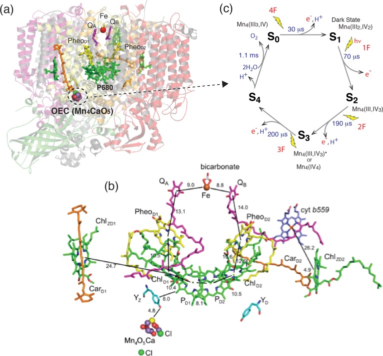
The OEC is embedded in Photosystem II (PS II), a membrane pigment–protein complex, where the primary charge separation by absorbed sunlight energy and successive electron transfer occurs through several vectorially arranged pigment molecules (Figure 1).9 The electrons and protons produced in the water oxidation reaction in PS II are ultimately used to store energy in the form of ATP and to reduce CO2 to carbohydrates via the Calvin–Benson cycle, and are the precursors for synthesis of the biological molecules needed by the organism. Nature has thus evolved an elegant way to store sunlight energy in the form of chemical energy, and it is this form of energy created by photosynthesis that all life depends on.
Figure 1.
(a) Photosystem II structure from 1.9 Å data from X-ray crystallography showing the membrane spanning helices and the extrinsic polypeptides. The location of the cofactors involved in charge separation and the Mn4CaO5 cluster in the membrane are shown highlighted against the polypeptide background. The Mn4CaO5 cluster is on the lumenal side of the membrane with the acceptor quinones on the stromal cytoplasmic side of the membrane. (b) Cofactors on both branches of PS II shown in detail. The distances between the groups are also indicated. The figure was drawn using the coordinates from the 1.9 Å structure. Adapted from ref (27). (c) S-state Kok scheme for oxygen evolution along with proposed oxidation states of Mn in the various intermediate S-states.
At present, the urgent need to develop renewable energy resources, which are essentially carbon-neutral, has highlighted the importance of learning how nature accomplishes this process and how water is oxidized to oxygen during photosynthesis.10−12 This knowledge could be critical for creating artificial photosynthetic devices. One of the key questions is how nature manages the uphill photoinduced water oxidation reaction by modulating the redox potential of each of the steps in the four electron redox reaction.
In the Bioinorganic Enzymology issue of Chemical Reviews in 1996, the Mn cluster in PS II was reviewed.13 In the almost 18 years since then, there has been an enormous amount of progress in the field with new studies in X-ray spectroscopy14,15 and crystallography,16−22 in addition to many other spectroscopic and biochemical studies, that have had a profound effect on the understanding of the structure and mechanism of photosynthetic water oxidation. In this review, we summarize the current understanding of the structure of the Mn4CaO5 cluster, as well as the water oxidation reaction based on the insights learned primarily from X-ray techniques since that last review. More comprehensive surveys of the literature in the field of oxygen evolution that emphasize other methods are provided in several excellent reviews.9,23−27
2. Photosystem II
2.1. Electron Transfer Chain
The past decade has seen impressive advances in the X-ray crystal structure of membrane proteins involved in photosynthesis. Since the first X-ray crystal structure of PS II from the thermophilic cyanobacteria at ∼3.8 Å was published in 2001,16 the resolution of the structure has steadily improved.17−20 The present X-ray crystal structure of PS II has been determined up to a resolution of 1.9 Å,21 and the details of PS II are shown in Figure 1a. This progress has had a major impact on the understanding of the structure of PS II and its components and their function, as well as the mechanism of light harvesting, charge separation, and catalysis.
The basic structural motif of PS II is very similar to that determined for the purple photosynthetic bacterial reaction centers,28 albeit with the addition of the OEC. The crystallographic asymmetric unit of PS II contains a dimer (700 kDa), and the two monomers are related by a noncrystallographic 2-fold axis perpendicular to the membrane plane. Each monomer consists of 17 or 18 membrane integral subunits composed of 35–36 transmembrane helices and 3 peripheral subunits. The monomer is characterized by pseudo-2-fold symmetry, which rotates the D1, CP47, and PsbI subunits into the D2, CP43, and PsbX subunits. Each monomer contains 35 chlorophyll a (Chl), 11–12 all-trans β-carotene molecules, 1 OEC (Mn4CaO5 cluster), 1 heme b, 1 heme c, 2 or 3 plastoquinones, 2 pheophytins, 1 nonheme Fe, and around 20–25 lipids.
Figure 1b shows the electron transfer chain in PS II where the light harvesting, charge separation, charge stabilization, and electron transfer take place. The P680 reaction center in the D1 and D2 subunits is the primary electron donor that traps the light energy delivered from the inner antenna subunits (CP43 and CP47 subunits) or the outer antenna complexes (LHC1 and LHC2) of PS II. The excited state of the primary donor P680·+ rapidly transfers the electron to ChlD1, pheophytin (PheoD1), and eventually to the acceptor, plastoquinone QA (a firmly bound plastoquinone), and subsequently to the final electron acceptor plastoquinone QB, stabilizing the charge separated state. Acceptor QB exits the pocket in PS II after accepting two electrons accompanied by protonation as plastoquinol QH2(B) and is released from PS II into the membrane matrix for transfer to the cytb6f complex, which mediates the electron between PS II and PS I. On the donor end of PS II, the cationic radical P680·+ is reduced by a tyrosine residue, TyrZ (D1Tyr161), to generate a neutral tyrosine radical TyrZ• that acts as an oxidant for the water oxidation process at the OEC.
The OEC cycles through a series of five intermediate S-states (Si, i = 0–4), representing the number of oxidizing equivalents stored on the OEC driven by the energy of the four successive photons absorbed by the PS II reaction center (Figure 1c).29 When PS II is dark-adapted, it relaxes to the S1 state (note that, although S0 is the most reduced state of the OEC, the S0 state is oxidized by tyrosine D(YD+) during the dark adaptation and therefore the S1 state becomes the dark-stable state). Illumination of dark-adapted PS II (the S1 state) with saturating flashes of visible light leads to a maximum O2 yield after the third flash, and then after every fourth flash. Each flash advances the oxidation state of the OEC by removal of one electron, and the OEC acts like a redox capacitor for the water oxidation reaction until the four oxidizing equivalents are accumulated (S4-state). Once four oxidizing equivalents are accumulated in the OEC (S4-state), a spontaneous reaction occurs that results in the oxidation of water, the release of O2, and the formation of the S0-state. Thus, the Mn4CaO5 complex in the OEC couples the four-electron oxidation of water with the one-electron photochemistry occurring at the PS II reaction center by acting as the locus of charge accumulation.9
During the reaction, the Mn cluster provides a high degree of redox and chemical flexibility, while the protein residues are critical for mediating the reaction by modulating the redox potentials and providing pathways for electrons, protons, substrate H2O, and product O2.30−32 PS II orchestrates the well-controlled catalytic reaction at close to the thermodynamic potential and also avoids releasing chemical intermediate species, such as superoxide or peroxide during the water oxidation reaction, that can be detrimental to the protein matrix.33
2.2. Oxygen-Evolving Complex and the Mn4Ca Cluster
The geometry of the Mn4CaO5 cluster in the OEC (Figure 2) has been revealed in the 1.9 Å crystal structure.21 Prior to the recent X-ray diffraction (XRD) studies, detailed extended X-ray absorption fine structure (EXAFS) studies,14,15,34 using solutions,35 oriented membranes,36−40 single crystals,41 and range-extended methods,42,43 have indicated that the Mn4CaOx cluster in the dark stable S1 state consisted of three di-μ-oxo and one mono-μ-oxo-bridged Mn–Mn interactions.44 The presence of Ca–Mn interactions is supported also by compelling evidence from EXAFS measurements obtained at the Ca and Sr edges of Sr-substituted PS II.14,45,46 The EXAFS studies showed that there are two Mn–Mn distances at ∼2.7 Å, one Mn–Mn distance at ∼2.8 Å, and one Mn–Mn distance at ∼3.3 Å,41,47 corresponding to the di-μ-oxo and mono-μ-oxo bridges, whereas the XRD model21 shows that the Mn–Mn distances are 2.8, 2.9, 3.0, and 3.3 Å. EXAFS studies have indicated four Ca–Mn distances between 3.4 and 3.9 Å compared to XRD studies that show three Ca–Mn at 3.4 Å and one at 3.8 Å. The combination of polarized EXAFS data from single crystals of dimeric PS II with XRD data19 led to several possible models for the Mn4CaO5 cluster.41 The models were constructed by considering the numbers of short and long Mn–Mn interactions and the changes in the amplitudes (dichroism). However, the crystal symmetry, the orientation of proteins within the unit cell, and the presence of the noncrystallographic C2-axis created limitations for uniquely solving the structure, and therefore multiple models exist. From the set of model structures that were derived, three were considered as most likely structures, of which one model is shown in Figure 3a that is almost a mirror image of the 1.9 Å XRD structure. There are differences in the distances between the XRD structure and the EXAFS derived structure as shown in Figure 3. This is likely caused by the X-ray-induced radiation damage during X-ray diffraction data collection and will be discussed in section 2.3.
Figure 2.
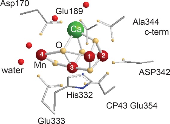
Structure of the Mn4CaO5 cluster with the residues that have been identified as ligands of Mn (crimson) and Ca (green) and four water molecules (in red) from the 1.9 Å X-ray crystal structure of PS II.21 Oxygen is shown in yellow.
Figure 3.
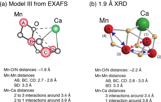
Structural models for the Mn4CaO5 cluster from (a) the polarized EXAFS and Sr EXAFS studies and (b) the 1.9 Å resolution XRD study.21 The Mn–Mn and Mn–O/N ligand distances from each of these studies are summarized below the respective structural model. Mn atoms are depicted in red, and Ca atoms are depicted in green. The O atoms are in gray in (a) and in yellow in (b). Reproduced with permission from ref (70). Copyright 2013 American Society for Biochemistry and Molecular Biology.
In the 1.9 Å crystal structural model (Figure 3), the metal ions in the cluster are bridged by 5 oxygens, whose positions were modeled based on omit maps. The distance Mn1–Mn3 of 3.3 Å and the corresponding Mn–O distances of 2.4 and 2.6 Å are much too long for bridging via a di-μ-oxo bridge, giving rise to the distorted nature of the cubane core of the cluster. Also the Mn–O distances in the μ-oxo bridges connecting Mn4 with the 3MnCa-core are elongated (2.4 and 2.5 Å) compared to the expected values for these distances in di-μ-oxo-bridges, probably due to the nondistinct or unclear position of O5 in the electron density. Ca is connected to the cluster via interactions with three of the bridging oxygens, leading to Mn–Ca distances of 3.3, 3.4, and 3.5 Å to the Mn in the core and 3.8 Å to the more isolated Mn4. There are some differences in the distances obtained from EXAFS studies and those observed in the 1.9 Å crystal structure. Some elongation is observed in the average Mn–O interactions (EXAFS: 1.9 Å, XRD: 2.2 Å) as well as the di-μ-oxo bridged Mn–Mn interactions (EXAFS: 2.7–2.8 Å, XRD: 2.8–3.0 Å). This is likely due to Mn reduction in the crystal structure during XRD data collection as described later in this section. Additionally, electron paramagnetic resonance/electron nuclear double resonance (EPR/ENDOR) studies suggest that Mn1 is 5-coordinate rather than 6-coordinate as shown in the crystal structure model.24
There are seven ligands directly ligated to the Mn4CaO5 cluster in the 1.9 Å crystal structure: six carboxyl ligands (aspartate and glutamate) and one imidazole ligand (histidine) (see Figure 2 for ligand environment and numbering). These ligands are from side chains from two domains of the D1 subunit, the interhelical CD luminal loop (residues Asp170 and Glu189) and the C-terminal region (between residues His332 and Ala344), and one domain of CP43—the large helical EF luminal loop. Most of the ligands are arranged in a bidentate fashion bridging two metals. Three of them, D1-Glu333, D1-Asp342, and CP43-Glu354, form di-μ-oxo bridges between Mn (Mn1–Mn2 (Asp342), Mn2–Mn3 (CP43-Glu354), and Mn3–Mn4 (Glu333)). D1-Asp170 and the C-terminal carboxylate group of D1-Ala344 bridge Ca with Mn4 and Mn2, respectively, and D1-Glu189 provides monodentate ligation to Mn1. The only His providing direct Mn ligation is D1-His332, binding Mn1. The second His in close proximity to the Mn4CaO5 cluster is D1-His337, which is too far for direct ligation of a Mn but is in hydrogen-bonding distance to the bridging oxygen involved in di-μ-oxo bridges between Mn1–Mn2 and Mn2–Mn3. In a similar manner, CP43-Arg357 ligates one of the oxygen bridges connecting Mn3–Mn4. Umena et al. located four water molecules bound to Mn/Ca in the electron density, in addition to the μ-oxo bridges and protein ligands.21 Two of the water molecules, W1 and W2, are bound to Mn4; the other two, W3 and W4, are bound to Ca. With the proposed ligation scheme, all Mn are fully coordinated, having six ligands each, and the Ca has seven ligands.
The differences observed in the atomic distances in the crystal structure and EXAFS data are likely due to a certain extent of reduction of Mn that occurs during the XRD data collection. Such changes are often seen in redox-active metalloproteins. The effects of X-ray-induced perturbations in PS II are summarized in the following section.
2.3. X-ray Radiation Damage to the Metal Cluster
One inherent problem of X-ray-related techniques for studying metalloproteins like PS II is the high radiation sensitivity of the redox-active metal cluster.48 In the case of PS II, specific radiation damage to the metal catalytic center occurs with relatively low X-ray dose even at cryogenic temperature, resulting in reduction of Mn and elongation of atomic distances, and destruction of the cluster is observed under conditions used for XRD.48 This makes it challenging to derive the structure of the intact S1 and the other intermediate states by XRD, as a high dose is required to obtain the crystal structure. The issue of radiation damage from X-rays to biological systems in crystallography is well-known,49−53 and it is a problem not only for PS II but also for other proteins that contain redox-active metals.
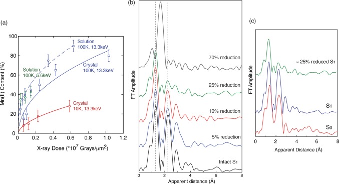
A quantitative study, using low-dose X-ray absorption near edge structure (XANES) measurements of PS II at 10 K after applying various doses under conditions similar to the ones used for X-ray diffraction measurements, showed that the oxidation state of Mn in the OEC changes from MnIIIMnIV to MnII with increasing dose.48 The percentage of MnII formed under different dose and temperature conditions was used as an estimate of damage (Figure 4a). From this study it was derived that under the conditions used for the earlier crystallographic studies at least 70–80% of the Mn was reduced to MnII. On the other hand, the radiation dose was significantly reduced in the 1.9 Å structure, and the degree of Mn reduction is estimated to be ∼25%. The reduction of Mn is accompanied by structural changes (disruption of μ-oxo bonds and changes of bond lengths) as indicated by Mn-EXAFS measurements under different dose conditions (Figure 4b).48,54
Figure 4.
(a) Radiation damage to PS II, measured as the amount of MnII detected, is plotted as a function of incoming X-ray dose from PS II solutions (dashed lines) and crystals (solid lines). The data at two different X-ray energies (13.3 keV, where XRD experiments are conducted, and 6.6 keV) and also at two different temperatures, 100 and 10 K, are shown. The damage is mitigated by lower temperatures. The dose used for the 1.9 Å crystal structure21 corresponds to only ∼25% damage, whereas the dose used for the earlier crystal structures18,19 is in excess of 70%. (b) EXAFS Fourier transforms (FTs) of PS II subjected to various degree, 5, 10, 25, and 70%, of damage compared to an FT collected with no damage (black). The decrease in intensity of the second and third FT peaks corresponds to losing the Mn–Mn and Mn–Ca distances and disruption of the bridged cluster. The first FT peak is mostly from the Mn–O bridging atoms and moves to longer distances; in the FT at 70% damage, only this one FT peak at longer distance is visible, which corresponds to that from Mn–O in the Mn(II) hexa-aquo species. (c) EXAFS FTs of PS II in S1, S0, and 25% reduced data. Figure 4a is adapted from ref (48).
The origin of the elongation of the atomic distances in the crystal structure has been discussed by several groups; one possibility is that the originally S1 state is reduced to the S0 state by the X-rays through the catalytic pathway.55 Other possibilities are the presence of pre-S0 states such as S–1, S–2, and S–3 states in the crystal structure based on the atomic distances.55,56 As shown in Figure 4c, the 25% radiation-damaged PS II EXAFS spectrum is substantially different from the intact S0 state spectrum. Also, 5–10% X-ray-reduced PS II spectra do not match with the intact S1 state spectrum. This implies that the reduction of the metal center by X-rays does not necessarily go through the catalytic pathway, as has also been shown for the MnFe ribonucleotide reductase.57
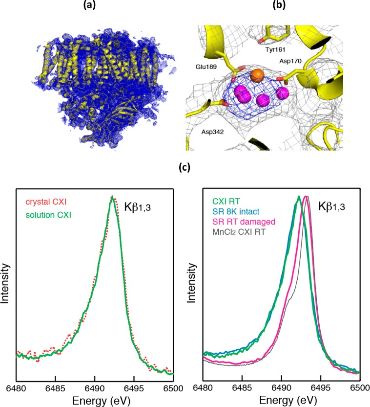
The degree of radiation damage in conventional crystallography can be decreased dramatically with the use of multiple crystals. Collecting data under liquid helium flow, instead of liquid nitrogen, could also help in reducing the effect. The use of X-ray-free electron lasers (XFELs) is also changing the way crystallography is being done on redox-active metalloenzymes58−60 including PS II61,62 as described in section 6.
3. Structural Changes of the Mn4CaO5 Cluster during the Catalytic Cycle
3.1. Dark Stable S1 State Structure
The geometry of the Mn4CaO5 cluster in the native dark S1 state has been the subject of intense study by spectroscopic methods, mostly electron paramagnetic resonance (EPR) and X-ray spectroscopy over the last three decades, and by the very promising X-ray crystallography studies over the last decade. The first indication of at least two di-μ-oxo bridges with Mn–Mn distance of 2.7 Å was established in the 1980s,63,64 followed by the finding of a mono-μ-oxo Mn–Mn distance of 3.3 Å65,66 and the orientation dependence of the Mn–Mn vectors.36,37,39,67,68 This was followed by EXAFS studies that established that Ca is part of the Mn cluster,66,69 leading to, at that time, a very novel idea for a heteronuclear Mn4Ca cluster. The determination that there are three Mn–Mn distances between 2.7 and 2.8 Å, and the subsequent polarized EXAFS of single crystals (Figure 5),41 dramatically reduced the number of possibilities for the geometry of the Mn4Ca cluster with open-cubane-like structures being proposed; one of them, model III, is shown in Figure 3a. The synthesis of inorganic complexes with features similar to those present in the OEC has been important for this evolving denouement of the structure of the Mn4Ca cluster.
Figure 5.
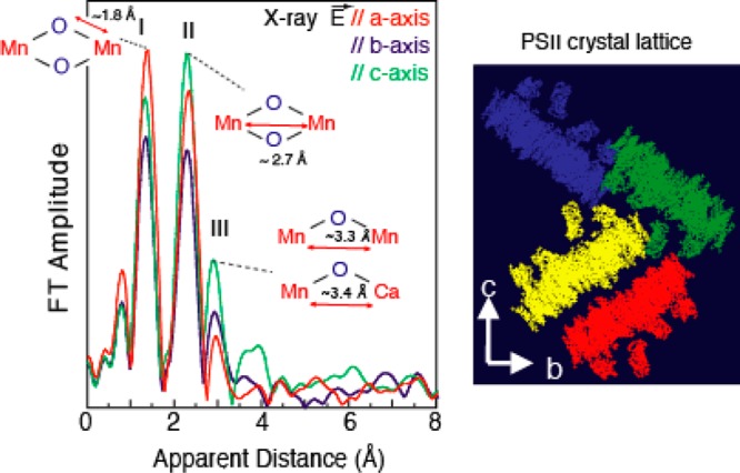
Fourier transforms of the EXAFS spectra from oriented PS II crystals on the left, with the e-vector of the X-rays parallel to the a, b, and c axes of the PS II crystal lattice shown on the right. The dichroism of the FT peaks is very clear and shows the asymmetric nature of the Mn–Mn and Mn–Ca vectors. This information was used to derive three possible structural models, and one of them (model III) is shown in Figure 3a. The modified version of the structural model based on the result of the 1.9 Å crystal structure21 is shown in Figure 6. Adapted from ref (41).
The most recent 1.9 Å XRD structure has provided much needed clarity to the geometry and a consensus among EPR,24 EXAFS,70 theoretical methods,71 and the XRD structure21 is getting close. On the basis of the geometry of the OEC from the crystal structure and the spectroscopic information from EPR and the polarized EXAFS of crystals of PS II, a possible intact S1 state structure has been proposed as shown in Figure 6. Single-crystal EXAFS on the S1 state has suggested an open-cubane motif where there are three Mn–Mn interactions at ∼2.7–2.8 Å and one Mn–Mn interaction at ∼3.2 Å as described previously. The EPR results also show that the Mn1, which is ligated to His332, is a 5-coordinated Mn(III) in the S2 state. Therefore, it is likely that the Mn1–O5 bond shown in the crystal structure is not present, leading to an open-cubane structure instead of a closed-cubane structure. A similar model geometry was suggested by Siegbahn using density functional theory (DFT) calculations.71We use the S1structural model shown inFigure6to further discuss the structural changes in other S-states in the following sections.
Figure 6.
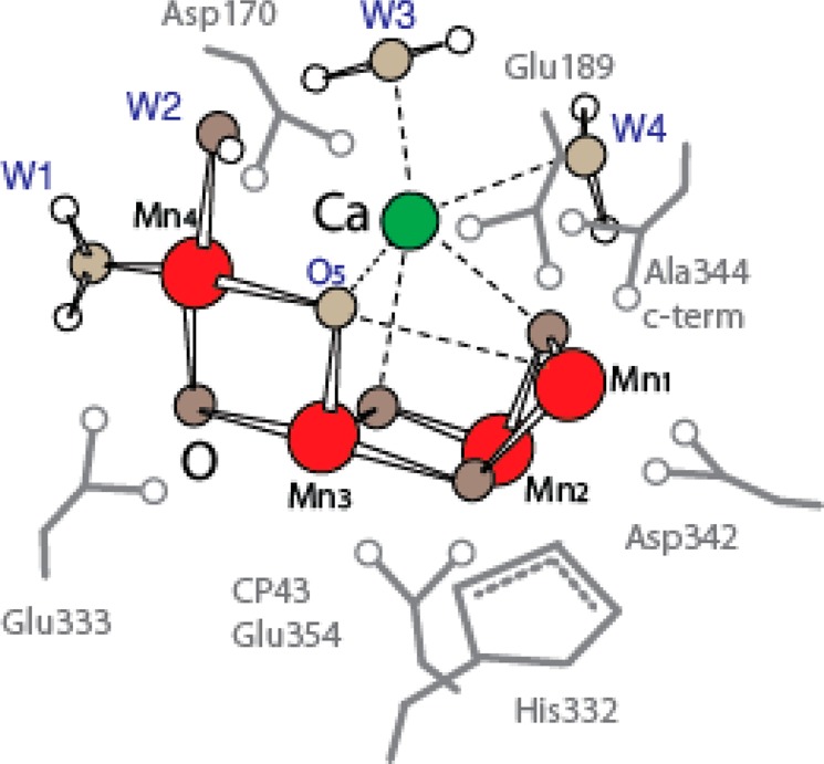
Spectroscopic model based on data from polarized Mn EXAFS, Sr EXAFS, and EPR data, starting from the geometry of the 1.9 Å crystal structure. This structure is also similar to that proposed on the basis of DFT calculations. The major difference between this model and the 1.9 Å structure shown in Figure 3b is the asymmetric placement of the bridging O between Mn4 and Mn1, leading to an open-structure compared to a closed-structure from XRD data. Adapted from ref (80).
3.2. Structural Changes of the Mn4CaO5 Cluster
Structural changes of the Mn4CaO5 cluster have been studied primarily by EXAFS methods, using native PS II as well as Sr EXAFS using Sr-substituted PS II instead of Ca. The S-state preparation for EXAFS studies has benefitted from using the oscillation of g = 2 multiline EPR spectrum (MLS) amplitude as a function of flash number. The pure S-state spectra were all extracted from deconvolutions that were based on fits to the EPR spectrum amplitude oscillations as shown in Figure 7.
Figure 7.

EXAFS data from the intermediate S-states is derived from PS II samples given 1–3 flashes. The samples do not advance completely to the next state because of misses and double hits, and hence, to obtain the pure S-state spectra, one needs to deconvolute the spectra. This is an important aspect of the spectroscopic data. This is normally accomplished by using the g = 2 multiline EPR signal from the S2 state. A typical EPR spectrum given 0–4 flashes (0F–4F) is shown in (a), with the oscillation in the intensity as a function of flashes, the best fit is shown in (b), and the calculated S-states are shown in (c). Using this matrix, one can then deconvolute the EXAFS spectra to obtain the pure S-state spectra in the S1, S2, S3, and S0 states.
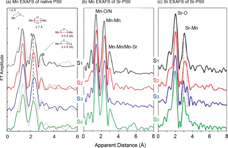
The EXAFS spectra of the PS II S-states show that the structure of the Mn4CaO5 cluster changes during the catalytic cycle. In particular, the short Mn–Mn interactions undergo distance changes in the range of 2.7–2.8 Å.47,70,72−74 Such distance changes can reflect several chemical parameters: Mn oxidation state changes, protonation state changes of bridging oxygens, ligation modes (e.g., bidentate/monodentate), and fundamental changes in geometry (i.e., dimeric, trimeric, or cubane-like structure). In the first case, Mn–ligand distances are shortened upon Mn oxidation from Mn(III) to Mn(IV), while Mn–Mn distances within Mn(III)/Mn(IV) and Mn(IV)/Mn(IV) multinuclear complexes strongly depend on the direction of the Jahn–Teller axis.75 When the protonation states of the bridging oxygens are changed, di-μ-oxo bridged Mn–Mn distance changes from 2.72 Å (bis-oxo), 2.84 Å (oxo/hydroxo), to 2.92 Å (bis-hydroxo).76 The Mn–Mn distances are in general longer in the cubane-like structure as compared with pure bis-μ-oxo dimer complexes.77 Therefore, such distance changes could serve as an indicator of the chemical structural changes that occur during the S-state transitions. Possible structural changes of the Mn4CaO5 cluster during the S-state transitions are derived from the Mn EXAFS and Sr EXAFS results shown in Figure 8.
Figure 8.
(a) Fourier-transformed spectra of PS II solutions in the S0 (green), S1 (black), S2 (red), and S3 (blue) states are shown. For comparison, the spectrum of the Sn–1 state is overlaid in the S1, S2, and S3 spectra (gray). Prominent changes between the S2 and the S3 state and the S3 and the S0 state in peak II of the FT spectra are indicated by a dashed line. All spectra are shown in the same scale but with a vertical offset. (b) FTs from Mn EXAFS of the S-states from Sr-PS II. (c) FTs from Sr EXAFS show the first FT peak from Sr–O and the second FT peak from Sr–Mn. The FT peak corresponding to Sr–Mn changes during the S-state cycle and most significantly for the S2 to S3 transition. Changes are indicated by dashed lines. (a) is adapted from ref (70). (b) and (c) are adapted from ref (73).
3.2.1. S1 to S2 (g = 2, MLS State) Transition
Among all the S-states, the S2 state is spectroscopically the most studied state as it is characterized by a rich EPR signal at g = 2. The OEC structure has been optimized by theoretical studies based on the 1.9 Å crystal structure, EXAFS distances, and EPR parameters.78 Therefore, considering the S-state structural changes starting from the S2 state is the most logical way to follow the EXAFS changes, and we will follow that method in this review. A distance change in the dark stable S1 to S2 state transition is observed, with a shortening of one Mn–Mn interaction around 2.7 Å, which is likely due to the oxidation state change of one Mn (formally Mn(III) to Mn(IV)) (Figure 9). The polarized EXAFS study of PS II single crystals41 supports the open-cubane-like structure that was also suggested by the theoretical studies of Siegbahn for S1 and S279 and Neese’s group for the S2 state80 characterized by the g = 2 multiline EPR signal (MLS).
Figure 9.
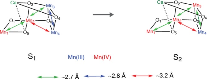
Possible structural changes described using the spectroscopic model for the Mn4CaO5 cluster for the S1 to S2 transition. The proposed oxidation states and the main Mn–Mn distances are shown.
3.2.2. S1 to S2 (g = 4 State) Transition
The S2 state can also be prepared in a different spin state characterized by an EPR signal at g = 4.1 in spinach preparations or at g ≈ 6–10 for preparations from cyanobacteria. The intricate relation between the S2-g4 and S2-g2 states and how they are related to the S1 and S3 states and their interconvertibility are shown in Figure 10a. The g2 and g4 EPR signals from the S2 state are shown in Figure 10b. The S2-g4 state from spinach was shown to involve Mn oxidation using Mn XANES, similar to the S2-g2 state.81 Earlier EXAFS studies also showed that there was a structural change between the S2-g2 and the S2-g4 states.82 Magnetic resonance studies have indicated a closed cubane-like structure for the S2-g4 state78 similar to that proposed from XRD studies in the S1 state.21 EXAFS studies of the Mn K-edge from the native spinach PS II show that the structure of the Mn4CaO5 cluster in S2-g4 state is distinctly different from that in the S2-g2 state. The EXAFS studies seem to indicate that the structure may not be a closed structure but another variation of the open structure (unpublished results). Note that a similar g = 4 EPR signal (S2-g4* in Figure 10a) can be produced by various chemical treatments, such as with F– or amines. However, these states do not advance to the S3 state. It is likely that S2-g4 and the S2-g4* states are chemically different.
Figure 10.
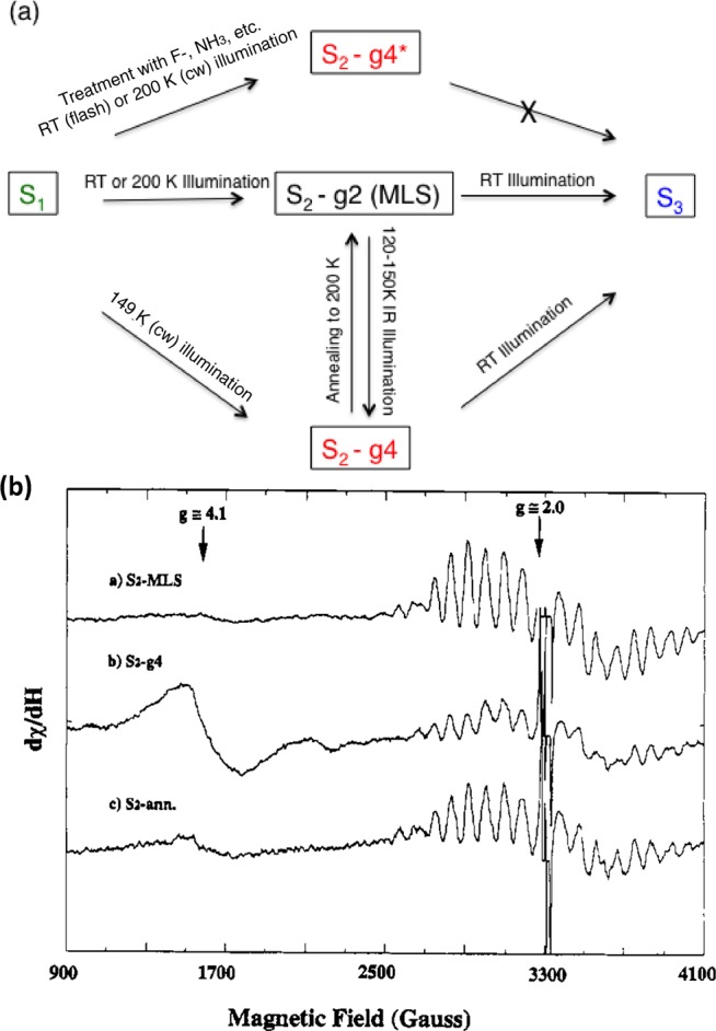
(a) Relation and interconvertibility of the S2-g2 and -g4 states. The S2-g2 state characterized by the multiline EPR signal can be generated from the S1 state by flash illumination at room temperature or 200 K (cw), while the S2-g4 state is generated by illumination of the S1 state at 140 K (cw)cor. The S2-g2 state can be converted to the g4 state by IR illumination at 120–140 K, and the g2 state can be produced from the g4 state by annealing at 200 K. A g4* state can be produced by treatment with F–, amines, and other treatments but cannot advance to the S3 state. (b) EPR signals from the g2 and g4 states and the g2-MLS signal generated from the g4 state by annealing at 200 K. Adapted from ref (82).
3.2.3. S2 to S3 Transition
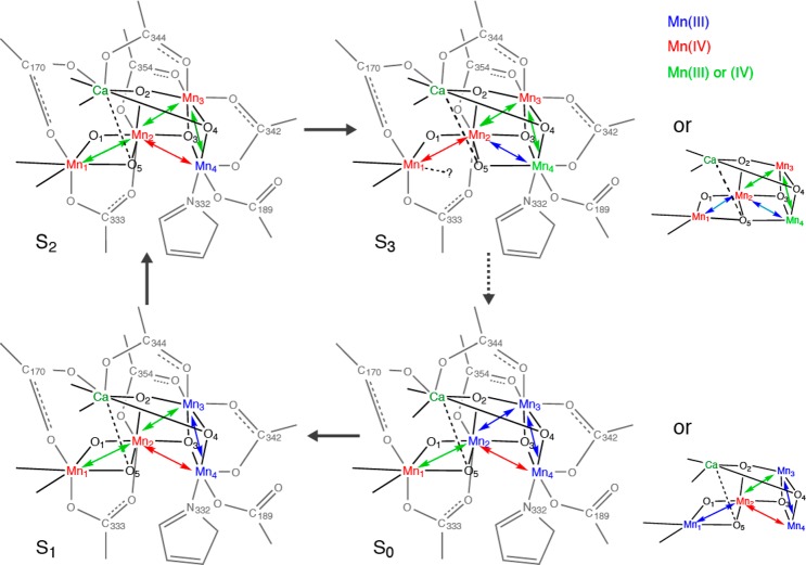
The S2 to S3 is clearly one of the most interesting transitions that have been studied by EXAFS, as the S3 state is the last stable S-state that can be cryogenically trapped and studied, before the last step (S4), where the O–O bond formation presumably occurs. Interestingly, elongations of the Mn–Mn interactions are observed in the S2 to S3 transition, unlike the S0 to S1 or S1 to S2 transitions.35,70,72−74 This suggests that the S2 to S3 step is not a simple one-oxidation state change of Mn, but is likely accompanied by fundamental changes of the Mn4CaO5 geometry. Elongation of Mn–Mn due to the oxo-bridge protonation83,84 is unlikely at the S2 to S3 transition, unless protons from terminal water molecules are transferred to the neighboring bridging oxygens. EXAFS studies suggest such structural change could occur by the shift of oxygen (O-5) position as illustrated in Figure 11 from Mn1 side to Mn4 side. Such O-5 shuffling possibility has been suggested by Pantazis et al.,78 but as a reason for the S2 low spin (S = 1/2) (multiline species) to S2 high spin (S = 5/2) (g = 4 species for spinach and g = 6–10 for T. elongatus) state changes, and by Isobe et al.85 in the S2 to S3 state transition.
Figure 11.

Possible structural changes described using the spectroscopic model for the Mn4CaO5 cluster for the S2 to S3 transition. The proposed oxidation states and the main Mn–Mn distances are shown. The two proposed S3 state structures are shown, where one of them is a closed structure.
If O-5 oxygen is moved toward the Mn3Ca open cubane site, a Mn3CaO4 closed cubane is formed in the S3 state. Thus far, Mn/Ca heteronuclear complexes have been synthesized by the Christou and Agapie groups.86−88 The MnIV3Ca2O structure reported by Mukherjee et al.88 has Mn–Mn interactions within the closed cubane structure with 2.73, 2.76, and 2.86 Å, with an averaged Mn-bridging oxygen distance of 1.86 Å. The MnIV3CaO4 structure reported by Kanady et al.86 has three Mn–Mn interactions at 2.83–2.84 Å with an average Mn-bridging oxygen distance of 1.87 Å. These Mn–Mn distances are longer than what is observed in the Mn dimer or trimer model complexes. The repositioning of O-5 could be accompanied by the ligand symmetry changes of Mn4, which becomes 6-coordinate from a 5-coordinate geometry.
Two possible structural models for the S3 state can be considered if an MnIV3CaO4 closed cubane-like moiety is formed in this state: one with 6-coordinated Mn1, and the other with 5-coordinated Mn1 upon O-5 shuffling. In the former case, the N number for the ∼2.7 Å Mn–Mn interactions becomes 2, and in the latter case it remains as 1.5. While the EXAFS fitting result slightly prefers N = 1.5, the result is not conclusive based only on the EXAFS curve fitting. In the latter case, Mn1 becomes 5-coordinated upon the S2 to S3 transition, or a new ligand, either water or carboxylate, needs to be ligated to maintain 6-coordination at Mn1. MnIV is in general 6-coordinate, but 5-coordinate structures have been proposed.89 In the pre-edge region, which is generally sensitive to the ligand symmetry, the intensity tends to increase upon S2 to S3 transition, which may suggest Mn1 to be 5-coordinated. This remains an open question, and a detailed pre-edge analysis combined with theoretical calculations will give us an insight into the ligand symmetry changes; such an approach is underway.
3.2.4. S3 to S0 Transition
Upon S3 to S0 transition via the S4 state, the Mn-ligand and the ∼2.7 Å Mn–Mn distances are shortened.47 This is counterintuitive if the Mn oxidation state changes from the most oxidized form (S3) to the most reduced state (S0). However, such changes could be explained if the Mn4CaO5 geometry in the S0 state is changed back to the one similar to the S1 and S2 states, where the Mn3Ca moiety takes the open-cubane-like structure (Figure 12).
Figure 12.
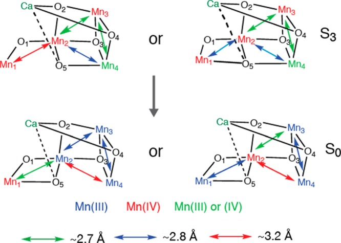
Possible structural changes described using the spectroscopic model for the Mn4CaO5 cluster for the S3 to S0 transition. The proposed oxidation states and the main Mn–Mn distances are shown. The two proposed S3 and S0 state structures are shown.
3.2.5. S0 to S1 Transition
The S0 to S1 transition is accompanied by the shortening of Mn-ligand distances as well as a Mn–Mn distance (∼2.8 to ∼2.7 Å) (Figure 13).47 The recent EPR/ENDOR study supports the formal oxidation state assignment of Mn4(III,III,III,IV) in the S0 state and Mn4(III,III,IV,IV) state in the S1 state.90,91 Therefore, the shortening of the Mn-ligand and Mn–Mn distances could be explained by the elimination of the Jahn–Teller effect at one Mn.
Figure 13.

Possible structural changes described using the spectroscopic model for the Mn4CaO5 cluster for the S0 to S1 transition.
The entire S-state cycle and a summary of the proposed structural changes based on X-ray spectroscopy data together with EPR and XRD studies is shown in Figure 14.
Figure 14.
Possible structural changes during the S-state transitions are illustrated. Note that the focus here is to accommodate the EXAFS distance changes, and possible protonation states (at oxo-bridging and terminal water molecules) or changes in the ligand environment (type of ligands and ligation modes) are not included in the figure. The Mn–Mn distances at ∼2.7 Å are indicated by green arrows, ∼ 2.8 Å by blue arrows and ∼3.2 Å by red arrows. The dashed line indicates that it may not be a bond. For the S3 and the S0 states, two possible models are presented. Mn atoms are shown in blue (MnIII), red (MnIV), or magenta (MnIII or MnIV possible), Ca is shown in green, and the surrounding ligand environment is shown in gray. Reproduced with permission from ref (70). Copyright 2013 American Society for Biochemistry and Molecular Biology.
3.3. Structural Changes and Calcium
Calcium is an essential element for the function of the OEC (reviewed in refs (46 and 92)). It has been speculated that Ca controls substrate water binding to the catalytic Mn site,93 and proposed mechanisms have suggested the involvement of Ca.46,94−98 Calcium can be depleted by several biochemical treatments that produce preparations in which O2 evolution activity is inhibited, but which can be reactivated by the addition of Ca2+. Reactivation of oxygen evolution in inhibited preparations can also be achieved by addition of Sr2+, reactivating the same number of centers as Ca2+, but with slower turnover in the S-state cycle, producing a lower overall rate of oxygen evolution at saturating light intensities.99,100 One study reports that vanadyl ion (VO2+) can also activate oxygen evolution.101 Na+, K+, Cd2+, and various lanthanides have been shown to compete with Ca2+ for binding sites in PS II, but none of them results in reactivation of oxygen evolution activity.92
3.3.1. Mn XAS and Ca or Sr
X-ray crystallography has confirmed the presence of Ca as a part of the OEC cluster.17−19,21,22,102−104 Prior to XRD, the presence of Ca in the OEC was detected using Ca and Sr XAS.38,69,105−107 A comparison of the Mn EXAFS of Ca-containing, Sr-substituted, and Ca-depleted PS II samples was the first study in 1995 that established the presence of a heteronuclear Mn4Ca complex in the OEC of PS II; such a Ca–transition metal mixed complex in biology had no precedence. Mn EXAFS on Sr-reactivated PS II membranes was interpreted to indicate a 3.4–3.5 Å distance between the Ca (Sr) and the Mn cluster.69 This conclusion was based on the observation of increased amplitude in Fourier peak III at 3.3 Å (Figure 15) upon replacement of Ca with Sr, a heavier atom and better X-ray scatterer. Such a short Mn–Sr/Ca distance was interpreted as indicating a direct Mn–O–Ca bridged structure in the OEC. The numbers of Mn–Ca(Sr) and Mn/Ca(Sr)-ligand vectors in the S0 to S3 states have been derived from Sr XAS.14,73,106,107 ESEEEM (electron spin echo envelope modulation) spectroscopy has been important for studying PS II108,109 and using 87Sr has shown the proximity of Sr to the Mn cluster,110 and a 113Cd-NMR study showed that Ca2+ is close to the Mn4-cluster.111
Figure 15.
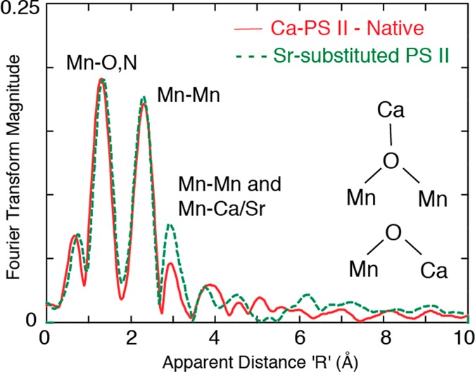
First Mn EXAFS study with Ca- and Sr-substituted samples that showed that there could be a Mn–Ca/Sr interaction at ∼3.3 Å. The FT peak amplitude at ∼3.3 Å increased on Sr substitution as expected from the higher scattering cross section of Sr compared to Ca. Adapted from ref (69).
3.3.2. Mn XAS and Ca Depletion
The structural consequences of calcium depletion of PS II has been determined by Mn XAS on PS II solutions105 and also using polarized EXAFS of oriented samples (unpublished results). XANES of Ca-depleted samples reveals that there is Mn oxidation for the Ca-depleted S1 to S2 transition.105 No evidence of Mn oxidation was found for the next illumination step. This is in line with the results from EPR studies where it has been found that the species oxidized to give the broad radical signal found in Ca-depleted PS II is tyrosine Yz (i.e., Ca-depleted S2YZ•).115 EXAFS measurements of Ca-depleted samples in the three modified S-states reveals that the Fourier peak due to scatterers at ∼3.3 Å from Mn, although strongly diminished, retains some amplitude.105 More, surprisingly, the orientation of the Mn–M vectors as determined from the polarized EXAFS showed minimal changes in Ca-depleted samples. The most pronounced differences are a lengthening of the Mn–Mn interaction around 3.2 Å by >0.1 Å in the Ca-depleted S1 state, accompanied by a tilt of ∼20° and smaller elongation of all Mn–Mn interactions upon advancement to higher oxidation states (Figure 16). The fact that Ca can be removed more easily in the S3 state (or that Ca can be more easily exchanged in the higher S-state)92,112,116−118 compared to the S1 and the S2 states, together with the above observations, implies that the Mn–Ca binding modes are changed upon S2 to S3 transition.
Figure 16.
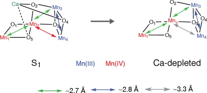
Possible structural changes described using the spectroscopic model for the Mn4CaO5 cluster for the S1 to Ca-depleted S1 state.
Recent Mn ENDOR results have also shown that removal of Ca does not perturb the magnetic properties of the Mn cluster, suggesting that the main bridging structure of Mn atoms is not changed by Ca removal.119 Therefore, we conclude that the removal of the Ca2+ ion from the OEC does not lead to fundamental distortion or rearrangement of the Mn cluster, indicating that the Ca2+ in the OEC is not essential for structural integrity of the cluster at least up to the S2 state. Presence of Ca, however, is necessary for the formation of the S3 state. A recent study by Rappaport et al. showed that Ca and a tyrosine residue of the D1 polypeptide (YZ) are involved in the common hydrogen-bond network, with Ca2+ facilitating the correct configuration of the hydrogen-bond network for proton transfer and therefore being important for the S2 to S3 transition that is accompanied by the proton transfer. On the other hand, there is no proton release upon S1 to S2 transition.
The fact that Ca-depletion does not affect the Mn4 structure together with the result that Ca can be removed or reconstituted during the S-state transition120−125 suggests that Ca is weakly bound to the Mn4 cluster in PS II. Sensitivity of Ca-depletion to NH2OH and hydroquinone treatment has suggested that the structural environment of the oxidizing side of PS II may be flexible, rather than rigid.117
A detailed study of the requirement of Ca in the S-state transitions has been reported by Miqyass et al.112 Despite the inability to complete the reaction cycle, the Ca2+-depleted S1 state can be advanced to higher oxidation states upon illumination. A Ca-depleted S2 state can be generated that is characterized by an EPR signal of at least 26 lines with an average line spacing of 55 G, centered at g = 1.96, which is different from that in the native state,113,114 and therefore it is different from the S2 state in the native system. A Ca-depleted S2YZ• can also be generated that exhibits a split EPR signal assigned to the YZ• radical interacting magnetically with the Mn complex in an S = 1/2 spin state.115 Thus, the Ca2+-depleted S2YZ• state cannot advance to the S3 state, as the Ca-depleted S2 state is not oxidized by YZ•.
3.3.3. Ca or Sr XAS
The first approach that was tried as described above69,126 was to substitute other metals (such as Sr) for Ca and then use Mn XAS to detect changes in the cluster. However, isolating the Mn–Ca or Sr component from the Mn EXAFS is often difficult, as other Mn–ligand and Mn–Mn interactions contribute in the same region. Alternatively, the reverse experiment probing backscattering from Mn using Ca or Sr EXAFS (Ca/Sr point-of-view for Mn) is more direct and definitive than Mn EXAFS results. Such studies on both isotropic and oriented PS II membranes have yielded unequivocal evidence for the proximity and mode of binding of Ca to the Mn4 cluster, as well as details about the orientation of the Ca/Sr in the PS II membrane and the changes in the structure of the cluster as it advances through the catalytic cycle.
Ca XAS
In a definitive experiment, Ca EXAFS was used to probe the structure of the Mn4CaO5 cluster from the Ca point of view to detect the distances of Mn atoms in the cluster. The use of Ca EXAFS spectroscopy has produced essentially congruent results with those found by Sr EXAFS on Sr-reactivated PS II106 and Mn EXAFS on similar samples,69 but it focused on native preparations, avoids the treatments involving Ca depletion and Sr substitution, and is a direct probe of the Ca binding site in PS II.
The FTs of the Ca EXAFS in Figure 17 are remarkably similar to the FTs of the Sr EXAFS study with Sr substituted for Ca. The first FT peak corresponds to the coordinating oxygen atoms closest to Ca. In contrast to the control (NH2OH-treated) sample where the Mn cluster is disrupted, the PS II samples with only 1Ca/4Mn shows a second FT peak, which corresponds to Mn at ∼3.4 Å. These observations resulted in the proposal that there exists a motif where the Ca/Sr is linked to at least two or three Mn.
Figure 17.
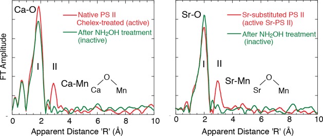
Ca EXAFS (left) and Sr EXAFS (right) both show scattering FT peaks from Mn in active preparations that are not present when the Mn4CaO5 cluster is disrupted using NH2OH. Both studies support a Mn–O–Ca bridging structure. Adapted from ref (46).
Sr XAS
Sr is favored for XAS study as the X-ray energies involved (16 keV for the K-edge) are more penetrating and not attenuated by air, and the higher X-ray absorption cross section and fluorescence yield of Sr makes the experiment more practical than Ca XAS. The Sr experiment requires PS II samples with Sr substituted for Ca while maintaining activity and a stoichiometry of 1 Sr per PS II, which were prepared biosynthentically from cyanobacteria grown in Sr medium.127
Sr EXAFS clearly showed the proximity of Sr (and implicitly Ca) to within 3.5 Å of the Mn cluster.106 The results are based on the presence of a second FT peak (peak II, Figure 17) in the Sr EXAFS from functional samples, a peak that is absent from inactive, hydroxylamine-treated PS II. This FT peak was found to fit best to two or three Mn at ∼3.5 Å rather than lighter atoms (C or O).
3.3.4. Orientation of Ca/Sr–Mn Interactions in the PS II Membrane
In Mn XAS of PS II, the presence of Fe in the sample places an inherent limit on the resolution of Mn distances by limiting the data length. While EXAFS spectra of dilute biological samples are normally collected with an energy-discriminating solid-state detector by electronically windowing the Kα from the metal atom, the low-energy resolution (∼ 200 eV) of the solid-state detector cannot completely discriminate Mn Kα from the Fe Kα signal, which limits the data length to k = 11.5 Å–1.128−130 This limitation has been overcome using a high-resolution crystal monochromator, to collect EXAFS beyond the Fe K-edge to k = 16.5 Å–1, improving the distance resolution to ∼0.1 Å. The method confirmed two distances to the short Mn–Mn interactions in the S1 and S2 states (two at ∼2.7 Å and one at ∼2.8 Å), whereas earlier solution EXAFS studies could discern only one distance of ∼2.7 Å. This range-extended EXAFS method combined with polarized detection using oriented PS II membranes for the first time allowed us to resolve the FT peak at ∼3.3 Å into one Mn–Mn vector at ∼3.2 Å and Mn–Ca vectors at ∼3.4 Å that are aligned at different angles to the membrane normal (Figure 18a–c).42 The dichroic behavior of peak IIIB is similar to that reported for the Mn–Sr vector (Figure 18d).38 The dichroism of these peaks has been used to determine the angle the Mn–Mn and Mn–Ca vectors make to the membrane normal.
Figure 18.
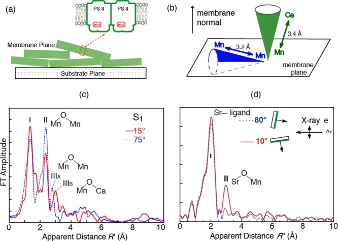
(a) Membranes of PS II can be oriented, and polarized EXAFS can be used to determine the orientation of Mn–Mn and Mn–Ca vectors with respect to the membrane. (b) Relative orientations of Mn–Mn and Mn–Ca vectors determined from the analysis of the data shown in (c) and (d). (c) Range-extended EXAFS of oriented membranes clearly shows the Mn–Mn vector at 3.2 Å and the Mn–Ca vector at 3.3 Å oriented differently in the PS II membrane. (d) Polarized Sr EXAFS shows the orientation of the Mn–Sr vector with respect to the membrane. Adapted from ref (46).
3.3.5. Changes of the Ca–Mn Distances During the S-State Transitions
Biosynthetically exchanged Ca/Sr-PS II preparations have made it possible to monitor Sr(Ca)–Mn distance changes in the four intermediate S-states, S0–S3, of the catalytic cycle by Sr XAS.131 Sr EXAFS data (Figure 8) in the S0–S3 states determined Sr–Mn distances at ∼3.5 Å (short) and ∼4.0 Å (long), and the data shows that all four Sr/Ca–Mn distances are detectable in all the S-state intermediates (Figure 19).73 Previous results from Ca EXAFS of plant PS II have shown that there are only 2–3 Mn–Ca interactions107 at <4 Å, compared to the four we have observed in Sr-PS II; it is possible that the longer interactions are at >4 Å or were not discernible at the S/N of the Ca EXAFS data.107 It is, however, difficult from Sr-XAS to determine if 2:2 or 3:1 short-to-long distance ratios are best. There is evidence that Ca protects two of the four Mn atoms from reductants, suggesting a closer interaction between Ca and two of the four Mn atoms in the cluster.132 The recent XRD data from Sr PS II indicates that Sr is at a slightly different location compared to Ca due to the larger ionic radius.22 The Ca- and Sr-PS II are slightly different in their kinetic and spectroscopic properties.131 This is likely due to the small perturbations of the hydrogen-bond network in the Sr-OEC, which reduces the proton-transfer efficiency and possible water molecule(s) delivery to the OEC as shown most recently by Rappaport et al.133
Figure 19.
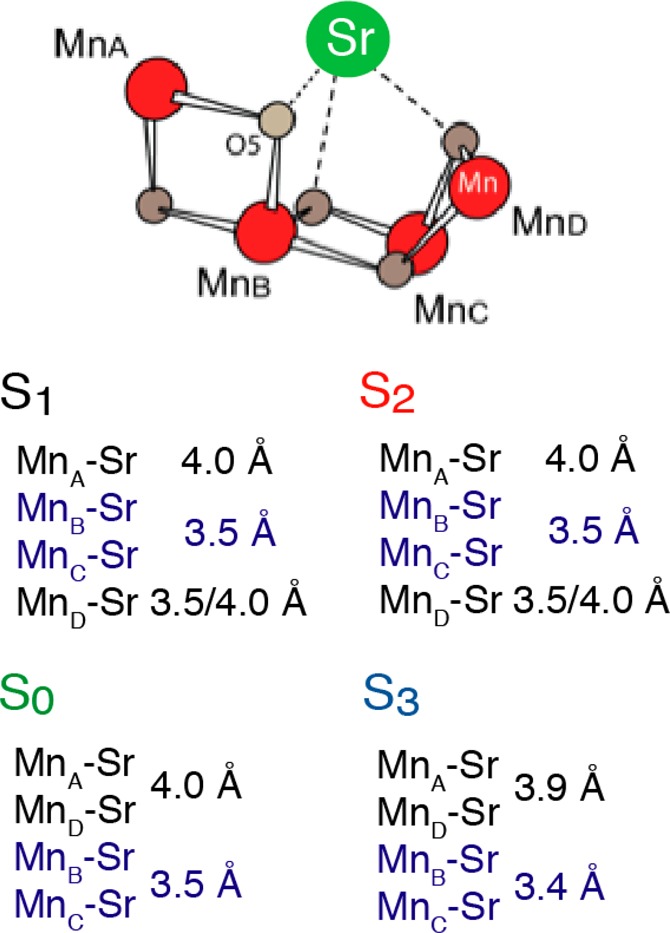
Summary of the Mn–Ca(Sr) distances in the S-states determined from Sr EXAFS. Adapted from ref (73).
In the S1 state, there are three or two Sr–Mn vectors at ∼3.5 Å and one or two Sr–Mn vectors at ∼4.0 Å. There are no significant changes in the Sr–Mn distances during the S1 to S2 transition, which is in line with the Mn XAS result; no substantial changes were observed in the Mn–Mn distances. Upon S2 to S3 transition, the FT peak II in Sr EXAFS splits in the S3 state (Figure 8c), indicating the distance changes in the Sr(Ca)–Mn interactions. The fact that Mn–Sr interactions change during the S2 to S3 transition is also in agreement with the different efficiency of Ca depletion in the S3-state from that in other S-states.120 Ca/Sr-depleted PS II cannot advance to the S3 state; instead, a state designated S2YZ• is formed, in which the Mn4-core structure is close to that of the S2 state and does not resemble the structure of the native S3 state.72,105 In the S3 to S0 transition, the Sr–Mn distances at 3.4 and 3.9 Å increase to 3.5 and 4.0 Å, respectively.
These results implicate the involvement of at least one common bridging oxygen atom between the Mn–Mn and Mn–Ca(Sr) atoms in the S2 to S3 transition. Because PS II cannot advance beyond the S2 state in preparations that lack Ca(Sr), these results show that Ca(Sr) is one of the critical components in the mechanism of the enzyme. The results also show that Ca is not just a spectator atom involved in providing a structural framework but is actively involved in the mechanism of water oxidation and represents a rare example of a catalytically active Ca cofactor.
3.4. Ligands of Mn and Ca and Site-Specific Mutants
In addition to the Mn4CaO5 core structural changes discussed previously, we expect that terminal ligands that are derived from carboxylates, histidine, and water/hydroxo ligands also likely change during the catalytic process. As shown in Figure 2, there are six carboxyl residues and one histidine residue directly ligated to the Mn4CaO5 cluster. Except for one glutamate residue (CP43-Glu354), other ligands to the Mn4CaO5 cluster are provided from the D1 subunit. There has been a series of mutagenesis studies to identify those amino acid residues that control the assembly and functioning of the Mn4CaO5 cluster and to gain insight on which Mn are involved in the different steps during the water oxidation reaction.27,31,134
Among the seven ligands, it has been shown that some ligands seem to be more critical than others in maintaining the OEC activity and the assembly process of the metal cluster.31 One of such ligands is D1-His332. The replacement of His332 by a glutamate residue results in a substantial geometric and electronic structural changes of the Mn4CaO5 cluster, which was observed in the EXAFS and XANES spectra (Figure 20, top).135 Although the metal cluster can be assembled in this altered ligand environment, the structure of the cluster is perturbed with an elongation of Mn–ligand and Mn–Mn distances. The Mn in the assembled cluster can be oxidized and advances from the EPR silent dark stable state to the one with an altered multiline EPR spectrum. It has also been shown by Sr EXAFS using Sr-substituted mutant samples that the Sr(Ca) is a part of the assembled structure. A possible reason for the altered structure of the cluster is a protonation of the oxo-bridge to restore the charge balance because of the replacement of a neutral histidine ligand by a negatively charged glutamate residue (Figure 20, bottom). An alternative explanation is a ligand environment change of the nearby carboxylate group, from a bidentate to a monodentate ligand. Therefore, the inhibition of the catalytic activity of the His332Glu mutant is because of the structural changes of the OEC itself during the assembly process.
Figure 20.
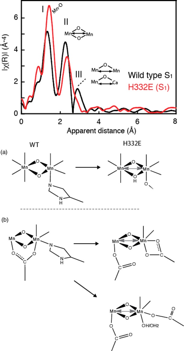
(Top) FT of Mn EXAFS from the wild-type compared with the mutant H332E. There is a clear difference in the FTs, indicating even more asymmetry in the mutant with possible modification of a Mn–Mn distance by replacement of a His ligand by a glutamate. (Bottom) Three different structural modifications are shown as a consequence of His replacement with Glu: (a) protonation of a bridge and (b) replacement of the bidendate ligand in two different ways. One is where the Glu binds only one Mn in a bidendate manner, while in the other it is monodendate, with the possible addition of a hydroxide or water ligand. Adapted from ref (135).
Mutagenesis studies have also examined the role of the CP43 protein. CP43-Glu354 is a bridging ligand for two metal ions in the native S1 state. First segment deletion studies were conducted, followed by site-directed mutagenesis. The point mutant, Glu354Gln, exhibits reduced photoautotrophic growth rate, although normal PS II content (e.g., no photoinactivation) and an 80% reduction in the O2 evolution rate were observed. Detailed spectroscopic studies on this mutant showed that the Glu354Gln mutation leads only to subtle changes in the structure and spin state of the Mn4CaO5 cluster in the S2 state. The water exchange study showed that the mutant weakens the binding of substrate water to the OEC.136
3.5. OEC in Monomeric and Dimeric PS II from Cyanobacteria
The existence of PS II in both a monomeric and dimeric form has provided the basis for controversial discussions, concerning their contribution to the functionality of the photosynthetic apparatus.137,138 This discussion in the past included the question whether PS II always exists in a dimeric form or whether a monomeric PS II is an equally active form. In general, the prevailing view is that the PS II dimer is the fully assembled and functionally relevant form, whereas the monomeric form is seen as an intermediate during the assembly process of all known 20 subunits of PS II and the repair cycle of photodamaged subunit D1.139,140 The assembly of PS II is a stepwise and highly regulated process,141 which includes many auxiliary proteins that are absent in the crystallized complexes. In cyanobacteria, an intermediate Psb27-PS II complex, which has no functional Mn cluster,142 regulates the assembly of the Mn4CaO5 cluster and the binding of the extrinsic subunits PsbO, PsbU, and PsbV143 prior to the dimerization of the PS II core complex. Monomerization of photodamaged PS II was suggested to be triggered by the detachment or structural reorganization of PsbO on the lumenal side.139,140
The chromatographic purification procedure of crude PS II extract yields essentially equal amounts of reaction centers in the monomeric and dimeric forms.144 The monomer/dimer ratio from 40 preparations was estimated to be 1.05 ± 0.45 based on the quantity of Chla.145 Moreover, it was shown that the monomeric and dimeric forms of PS II are similar in their oxygen-evolving capacity as well as in their subunit content. The crystal structure of monomeric PS II, albeit available at medium resolution so far, does not give indications of either a destabilization of subunit D1 or a structural reorganization of subunit PsbO. The Mn EXAFS spectra from dimeric and monomeric PS II in Figure 21 show that they are almost identical.
Figure 21.
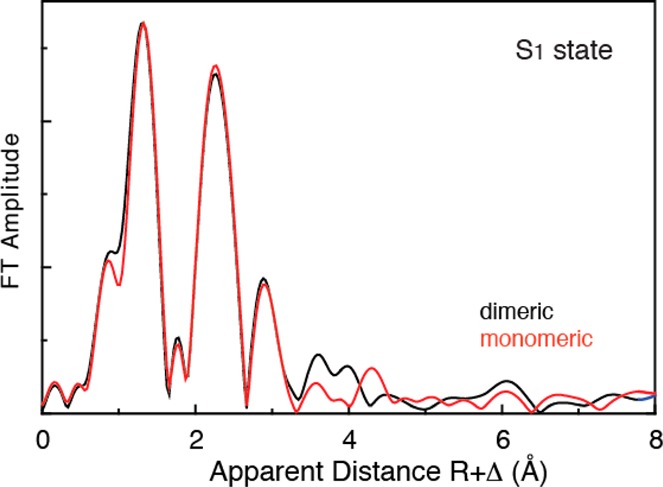
Mn EXAFS spectra from monomeric and dimeric PS II. There are no differences in the Mn4CaO5 structures that are detectable from EXAFS between the dimeric and monomeric PS II.
4. Electronic Structure of the Mn4CaO5 Cluster
The Mn4CaO5 cluster goes through five intermediate states during the water oxidation reaction triggered by the absorbed light (Figure 1c). The cluster stores oxidizing equivalents until the release of molecular oxygen in the final (S4–S0) step and then goes back to the most reduced form in the S0 state by incorporating two water molecules. The protein residues such as carboxylate and histidine ligands provide a high degree of chemical flexibility to the cluster and stabilize multiple oxidation states. To understand the mechanism of water oxidation in detail, it is crucial to understand the changes of the electronic structure in the OEC over the whole course of the catalytic cycle.146 The primary questions include whether the electrons extracted from the OEC are directly derived from bound water, or from the Mn atoms, or from any other parts of the OEC accompanying each S-state transition,23 and how the ligand environment modulates the d orbitals and the electronic structure of the Mn to tune the redox potential during the catalytic process.147−149
Oxidation and spin states of the cryo-trapped intermediate states (S0–S3 states) have been studied intensively by various spectroscopic methods such as EPR,24,150 Fourier transform infrared (FTIR),151−153 XANES,146,154−159 and UV–vis spectroscopy.160−162 EPR spectroscopy shows that S0 and S2 have spin S = 1/2 ground states, exhibiting MLS EPR (note that there are also high-spin species observed in the S2 state; see section 3.2.2).150,163−167 The S1 and S3 are characterized by parallel-polarized EPR signals, indicating integral spin ground states.168−171 Through these studies, there is an overall consensus that Mn-centered oxidation occurs through the S0, S1, to S2 transitions. Within the context of localized oxidation, the formal oxidation state of the native S1 state has been assigned to Mn2IIIMn2IV and S2 has been assigned to MnIIIMn3IV. In the S0 state, one of the questions is whether MnII is present, in which case the oxidation states are MnIIMnIIIMn2IV,166,172,173 or whether the oxidation states are Mn3IIIMnIV. Recent ENDOR studies have provided the evidence of the latter case.90 In the S2 to S3 transition, there has been a discussion about whether a Mn-centered oxidation occurs154,174 or a ligand-centered oxidation takes place.159,175 There have also been proponents of a lower oxidation state process for the entire cycle starting with a Mn4III for the S1 state,176−178 although the evidence from EPR24 and X-ray spectroscopy,14,154 and NH2OH and hydroquinone-induced reduction of the Mn,179 supports the higher oxidation states, with Mn2IIIMn2IV in the S1 state.
As described above, the nature of the electronic structure has been discussed only within the context of the formal oxidation state of Mn. This is partly the reason for the controversy concerning the assignment of the oxidation state in the S3 state.74,159 Although there are distinct chemical characteristics in the formal oxidation states, convenient, formal oxidation states do not necessarily coincide with the effective number of electrons in the metal valence shells. In this regard, for many transition-metal systems, the formal oxidation state is an incomplete, and in many cases incorrect description of the electronic structure of the system, because of other important factors, especially metal–ligand covalency.180−183 It is therefore necessary to understand the electronic structure beyond the formal oxidation state and how PS II manages electron localization and controls their paths using the flexible protein environment; this may be an important aspect for learning the design concept of the catalytic reaction and applying it to artificial photosynthetic devices.
Since the 1.9 Å crystal structure has revealed the Mn4CaO4 cluster geometry, theoretical interpretations of the EPR/ENDOR and X-ray spectra based on the geometry and detailed comparison to the model compounds have become possible. Additionally, advancement of the theoretical approaches, together with experimental methods in the last few decades, has helped in advancing the understanding of the nature of the Mn4CaO5 cluster as described in the sections below.
4.1. Electronic Structure Probed by X-ray Spectroscopy
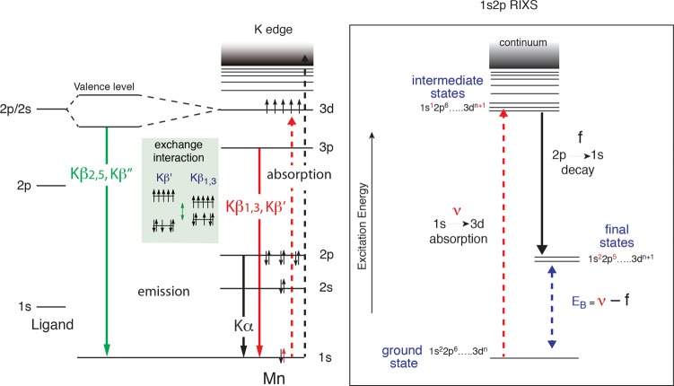
Various X-ray spectroscopic approaches have provided an element-specific view of the electronic structural changes of the Mn4CaO5 cluster, and these techniques complement each other by probing the electronic configurations with different sensitivity and selection rules. Figure 22 summarizes the energy level diagram for the X-ray spectroscopy techniques we describe here, which include X-ray absorption spectroscopy (XAS), X-ray emission spectroscopy (XES), and resonant inelastic X-ray scattering spectroscopy (RIXS).
Figure 22.
(Left) Energy level diagram for K-emission. The dashed line (black) is the excitation into the continuum. The solid lines are the emission lines, black is 2p to 1s (Kα), red is 3p to 1s (Kβ1,3 and Kβ′), and green is valence orbitals to metal 1s (Kβ2,5 and Kβ″). The exchange interaction between the 3p and 3d makes the Kβ1,3 and the Kβ′ sensitive to the number of unpaired electrons in the 3d level and therefore the charge density (oxidation states) of Mn. The valence-to-core Kβ2,5 and Kβ″ involve the 2s and 2p levels from the ligand atoms and, hence, are sensitive to the electronic environment of the ligand. (Right) 1s2p RIXS energy level diagram. The excitation energy from 1s to 3d levels is shown as a dashed red line and is scanned using a monochromator, and the 2p-1s (Kα) emission is detected using a spherically bent crystal analyzer spectrometer. The difference between the excitation and the emission energies gives the 2p to 3d transitions, which is equivalent to the L-edges. The RIXS spectra can be used to obtain both the K-pre-edge and L-edge spectra.
XAS probes the unoccupied orbitals of the metals of interests. The K-edge pre-edge region is due to the metal 1s to 3d transitions; its peak position is sensitive to the d-orbital multiplicity and ligand symmetry, and the intensity is related to the covalency. XES is complementary to XAS and provides a direct probe of the occupied molecular orbitals. In a Kβ XES spectrum, the Kβ1,3 and Kβ′ correspond to a transition from a metal 3p orbital to a metal 1s hole. Because of a strong contribution from 3p-3d exchange contribution, this region of the spectrum is dominantly influenced by the spin state of the metal. To higher energy are the valence-to-core transitions (or also called Kβ2,5 and Kβ″). These features correspond primarily to transitions from ligand 2p and 2s orbitals to metal 1s, respectively, and as such contain direct information about the ligand identities.
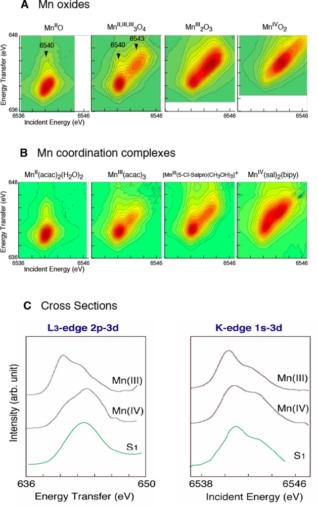
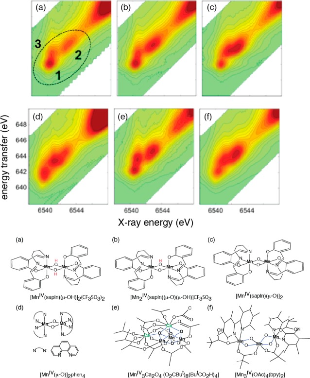
The electronic structure of the metal complex can be studied in more detail using RIXS, which is sensitive to both metal charge density and spin state.184,185 In 1s2p RIXS (Figure 22), a Mn 1s electron is excited into the lowest unoccupied molecular orbitals (LUMOs). The orbitals have mainly Mn 3d character mixed with Mn 4p and ligand orbitals. The electronic configuration can be approximated by 1s13dn+1. After the absorption, the most probable decay process is 2p to 1s to reach the final state configuration 2p53dn+1. In the RIXS measurement, both the incident X-ray energy (ν) and the emission energy (f) are scanned and the energy difference between the initial state and the intermediate state (ν) is equivalent to the K-edge pre-edge transition, and the difference between the initial state and the final state (ν – f) is comparable to L-edge spectroscopy. Because of the strong (2p, 3d) multiplet interaction, L-edge spectra are more sensitive to the metal spin state; therefore, RIXS is sensitive not only to the metal charge density but also to the metal spin state. In general, L-edge spectroscopy is difficult for biological samples because of severe radiation damage caused by the higher X-ray absorption at lower X-ray energy region, and additionally experiments need to be carried out under ultrahigh vacuum conditions. In RIXS, on the other hand, L-edge-like spectra are obtained with the excitation energy in the energy range of K-edge spectroscopy, and therefore the degree of radiation damage is comparable to that of the K-edge spectroscopy and can be avoided by collecting data at cryogenic temperature. Hence, RIXS spectroscopy can circumvent some difficulties in the L-edge spectroscopy, which makes this method suitable for biological samples. In the following section, we summarize the current understanding of the electronic structure of the OEC using these three techniques.
4.2. Mn K-edge Absorption Spectra of PS II
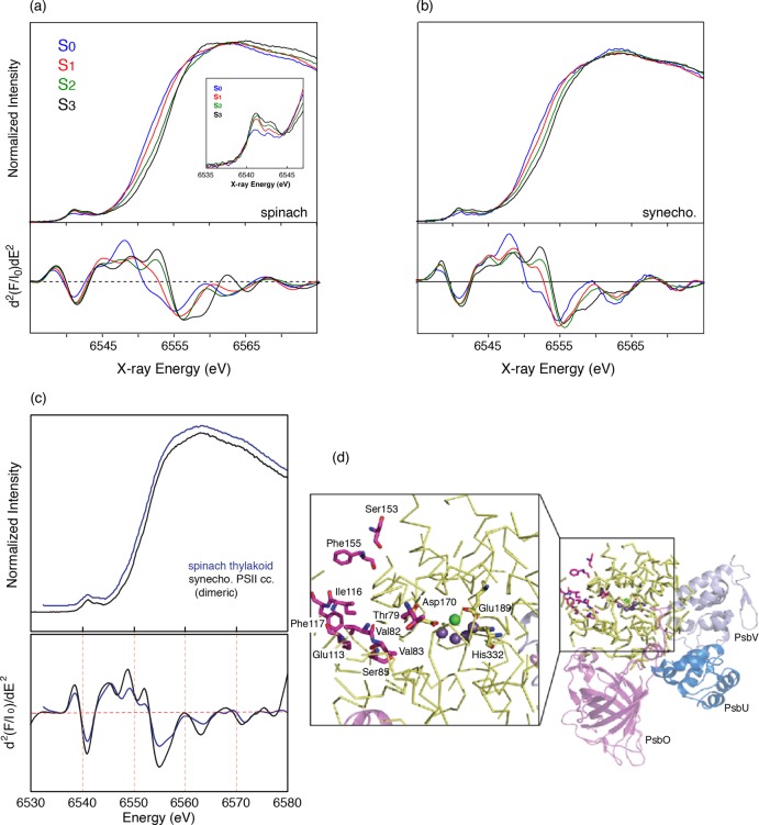
Figure 23a, b show the X-ray absorption near edge spectra (XANES) of PS II solutions from cyanobacteria and spinach thylakoid membrane from S0 to S3 states. Pure S-state spectra were obtained by deconvoluting the spectra of flash samples (0F–3F) using the S-state distributions obtained from EPR spectroscopy. A typical distribution of S-states is shown in Figure 7c.
Figure 23.
(a) (Top) Mn XANES spectra from spinach PS II in all the S-states and (Bottom) the second derivatives of the Mn K-edge XANES. The inset shows the pre-edges in all the S-states. (b) (Top) Mn XANES spectra from cyanobacterial PS II in all the S-states and (Bottom) the second derivatives of the Mn K-edge XANES. The similarities in the Mn K-edge shifts in energy between spinach and cyanobacterial PS II are very clear. There are only small changes in the shape as seen in the second derivatives at around 6560 eV. The shifts in energy between the S0 to S1 and S1 to S2 are much larger than that seen for the S2 to S3 transition. This is particularly clear from the zero-crossing of the second derivatives. (c) (Top) Mn XANES spectra from spinach PS II (BBYs) and cyanobacterial PS II preparations in the dimeric form and (Bottom) the second derivatives of the Mn K-edge XANES. There are small differences in shape between the spinach and cyanobacterial PS II. These differences could arise from differences in the second sphere interactions with the Mn4Ca cluster and H-bonding network. (d) Amino acid residues within a radius of 20 Å around the Mn4Ca cluster according to the structural model of PS II from T. elongatus at 2.9 Å resolution. The right panel shows in yellow (ribbon mode) the amino acid residues within a radius of 20 Å around the Mn4Ca cluster (Mn, purple spheres; Ca, green sphere). Amino acids of subunit D1 different from spinach are highlighted in pink and are labeled in the enlarged view on the left. For better orientation, the amino acid residues Asp170, Glu189, and His332 (all of subunit D1, yellow) are labeled and are shown in stick mode. The extrinsic subunits PsbO (purple), PsbU (blue), and PsbV (light blue) are shown in cartoon mode. The view is of one monomer looking onto the monomer–monomer interface along the membrane plane (tilted by 45° to the left), with the cytoplasm above and the lumen below. (d) Adapted from ref (70).
The overall trend of the XANES edge shift is similar between the PS II from cyanobacteria and spinach thylakoid membrane preparations. The edge position shifts to higher energy during the S0 to S3 transitions. The zero-crossing energies of the rising edge spectrum, which are often used as an indicator of the oxidation state, are 6550.9 eV for S0, 6553.5 eV for S1, 6554.1 eV for S2, and 6554.4 eV for S3 in cyanobacteria PS II,70 and 6550.8, 6552.9, 6554.0, and 6554.3 eV, respectively, in spinach thylakoid membrane. Note that these numbers differ depending on the methods used,174 but the zero-crossing of the second-derivative method used by Messinger et al. avoids any problems with background contributions.159 On the basis of this result, Messinger et al.159 interpreted that Mn oxidation occurs during the S0 to S1 and S1 to S2 state transitions based on the 1–2 eV XANES energy shifts. On the other hand, a much smaller shift was observed in the S2 to S3 state transition, which suggests that the chemical changes during the S2 to S3 state transition are not the same as the ones during the S0 to S1 and S1 to S2 state transitions. One possible explanation for this was that a unit other than Mn (i.e., oxygen ligands) is oxidized during the S2 to S3 state transition. However, it is worth noting that the XANES edge shape changes and edge shift could be more complicated when the transition is accompanied by structural changes. Haumann et al.74 showed that the small edge shift and the shape change could occur when one Mn coordination state changes from five to six, based on the XANES feature observed in the S2 and the S3 states.186 Such coordination changes are also suggested by theoretical models and EPR studies.24,25,71 As shown in the previous section, the structural changes observed in the S2 to S3 state transition are more substantial compared with other S-state transitions. In the spectroscopic model (Figure 6), Mn1 is suggested to be Mn(III) in the S1 state from the EPR study, alternative to the 6-coordinated structure in the 1.9 Å crystal structure. If Mn1 is oxidized in the S2 to S3 transition and becomes Mn(IV), it is likely that the sixth ligand, which could be O5 or, as proposed by Siegbahn,187 a water/hydroxo ligand, is ligated to Mn1 in the S3 state.
In addition to the main Mn K-edge, one can also study the 1s to 3d pre-edge spectra that arise from 1s to 3d transitions, by probing orbitals that are mainly localized around the metal ion. It shows the immediate surrounding of the excited ion through the Coulomb interaction between the core hole and the valence electrons. This pre-edge feature is a quadrupole-allowed transition and without any dipole contribution is usually very weak compared to the intensity of the dipole-allowed main edge transition. The transition can gain intensity by the metal 4p mixing when the metal–ligand environment is distorted from a centro-symmetric to a noncentro-symmetric coordination. The spectra reflect coordination number, ligand environment, and oxidation state of metals.
The pre-edge spectra of PS II in Figure 23a (inset, see also Figure 27 for fits to the pre-edge) noticeably change during the S-state transition.159 There are mainly three peaks, and the low-energy component (∼6540 eV) decreases in intensity during the S0 to S1 and S1 to S2 transitions and is not present in the S3 spectrum. In the single-crystal XANES of PS II S1 state, these three components show a characteristic dichroism.41 Such dichroism has been investigated in Mn model complexes, like Mn(V) mononuclear low spin complex,188 which has shown the potential of polarized experiments and also the complementary DFT theory that can be used to understand the electronic structure. To understand these pre-edge features and obtain information about the electronic configuration of PS II, however, one needs to further investigate the various model compounds and combine experimental data with theoretical calculations based on ligand field theory and/or DFT.
Figure 27.
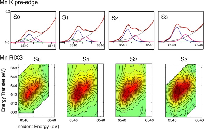
(Top) K absorption pre-edges and fits for PS II in S0–S3 states (red, experimental data; black, fit; blue, pink, and green, peak components; dark gray, background). There is a lower energy peak in the fits for the S0 and S1 states, which is decreased in the S2 and S3 states. The higher-energy component increases in intensity in the S2 to S3 transition, which is consistent with the increase in Mn(IV). (Bottom) RIXS contours for PS II in S0–S3 states. The spectral changes are more subtle than those seen for the oxides and coordination complexes in Figure 26 and also compared to the multinuclear complexes in Figure 28. Adapted from ref (197).
4.2.1. Comparison of OEC from Plants and Cyanobacteria
While overall trends are similar in the spinach PS II and cyanobacterial PS II XANES, small changes are observed that are more visible in the second derivative spectra. This is in agreement with the results of Su et al.189 who concluded that the electronic structure of the Mn cluster is very similar but not identical between both species, based on comparison of the S2 multiline and the S2 Mn ENDOR signal from spinach and the cyanoacterial PS II from T. elongatus.
The alignment of the amino acid sequence of the D1 protein (subunit PsbA) from T. elongatus and spinach showed a sequence identity of 84.7%. 305 positions are identical and 36 are similar. Within a radius of 20 Å around the OEC, nine amino acid residues are not fully conserved, but eight of them are conserved between groups with strongly similar properties. This high conservation makes it unlikely that the slight differences between spinach and T. elongatus PS II XANES spectra (Figure 23c) are due to the differences in the D1 protein. This is also true for subunit CP43 (providing one of the ligands to the Mn4CaO5 cluster) with all residues in the vicinity of the OEC being highly conserved between T. elongatus and spinach.
The subunit compositions of spinach PS II and cyanobacterial PS II are slightly different. While PS II from cyanobacteria have the extrinsic subunits PsbO, PsbU, and PsbV, spinach PS II has neither PsbU nor PsbV but the proteins PsbP and PsbQ instead. The exact localization of PsbP and PsbQ is not yet resolved, but various studies found these two subunits to be important for the stability and activity of the OEC (for review, see refs (190−192) and references therein). PsbV and PsbU are found to bind in the vicinity of the OEC with closest distances to Mn of 11 Å (PsbV-K160) and 14 Å (PsbU-Y133), respectively, and thereby they directly interact with the C-terminus of the D1 protein. Replacing these subunits with PsbP and PsbQ might induce structural changes in the vicinity of the OEC, which could cause the slight variations visible in the XAS spectra, demonstrating the sensitivity of XAS for subtle changes in the electronic structure.
4.3. Mn X-ray Emission Spectra of PS II
4.3.1. Kβ1,3 Transitions
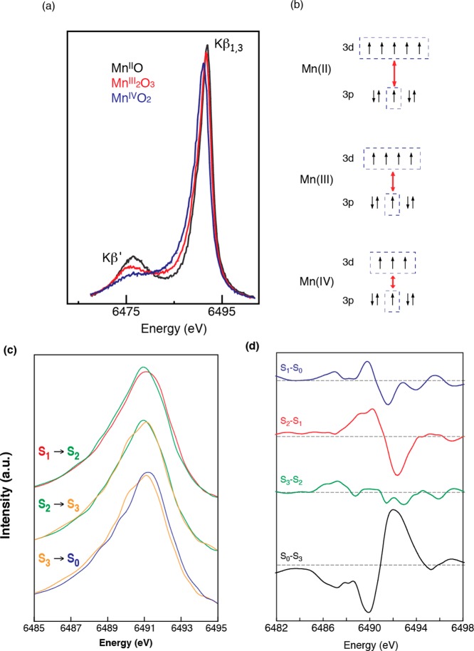
Spectral changes in the Kβ main lines reflect the effective number of unpaired metal 3d electrons through the exchange interaction between the core hole (1s or 2p) and the net electron spin in the metal valence shell by the (3p, 3d) exchange interaction. In general, spectral changes for Kβ lines are more pronounced than for Kα, because the 3p and 3d orbitals interact more with each other than the 2p and 3d orbitals. In a very simplified model of the two final spin states, Kβ1,3 is a constructive and Kβ′ is a destructive spin-exchange interaction between the unpaired 3p and 3d electrons (Figure 24). The magnitude of the exchange interaction depends on the number of unpaired electrons in the 3p and 3d orbitals. Thus, the Kβ spectrum serves as an indicator of oxidation state that is different from XANES, which monitors oxidation state through 1s core hole shielding effect. Figure 24a shows the Kβ emission spectra of a series of Mn oxides, Mn(IV)O2, Mn2(III)O3, and Mn(II)O, which illustrate the sensitivity of Kβ spectra to the oxidation state of Mn.193 As the oxidation state of Mn increases from Mn(II) to Mn(III) to Mn(IV), fewer unpaired 3d valence electrons are available to interact with the 3p hole; concomitantly, the magnitude of the 3p-3d spin exchange interaction becomes smaller. Accordingly, the Kβ1,3 transition shifts to a lower energy, the Kβ′ transition shifts to a higher energy, and the Kβ′–Kβ1,3 splitting becomes smaller (Figure 24b).
Figure 24.
(a) Kβ1,3 and Kβ′ spectra from MnII, MnIII, MnIV oxides. (b) 3p-3d exchange coupling that shows how the Kβ1,3 and Kβ′ spectra are sensitive to the oxidation and spin state of Mn. (c) Kβ1,3 spectra of the S-states. (d) Difference spectra which show that the shifts are larger for the S0 to S1, S1 to S2, and S3 to S0 transitions. The S2 to S3 transition is the smallest. Adapted from ref (146).
Kβ XES is less sensitive to the ligand environment compared to XANES, as the 3p orbitals have less overlap with the ligand orbitals compared to the 4p orbitals. This is demonstrated in the XANES and XES spectra of two types of Mn compounds, with very different structures such as the “trimers” (trinuclear complexes) and “butterflies” (tetranuclear), in different oxidation states.194 In the XANES spectra, the Mn oxidation state changes have clear effects on the inflection point energy (IPE) shifts: the shift is 1.64 eV for Mn3O and 2.20 eV for Mn4O2, with the magnitude of the shift depending on the type of compounds. On the other hand, the Kβ energy shifts from one oxidation state to another are more or less the same between these two series; the shifts scale with the fractional change in oxidation state: 0.12 eV for Mn3O (1 of 3) and 0.09 eV for Mn4O2 (1 of 4). This shows that, compared to XANES, Kβ XES primarily reflects the changes in oxidation state rather than differences in the overall ligand environment.
The Kβ emission spectra of PS II in S0–S3 and their difference spectra are shown in Figure 24c, d. The derivative shape of the S0 to S1 and the S1 to S2 difference spectra show that the Kβ1,3 peak shifts to lower energy during these transitions. By contrast, the change is not apparent upon the S2 to S3 transition, suggesting that the change in the metal charge density is much less than for the other transitions. Mn reduction occurs during the S3 to S0 state transition, and the Kβ1,3 peak shifts to a higher energy; the difference spectrum reflects a return to the starting oxidation states. The first moment energy was calculated for each spectrum using the following equation (eq 2),
| 2 |
and used as an indicator of the effective charge density,159,193 where Ej and Ij are the energy and fluorescence intensities of the jth data point. The method is suited for very small shifts because the statistics from the entire Kβ1,3 (6485–6495 eV) peak is considered rather than just the peak energy.
Figure 25 summarizes the IPE (inflection point energy) from the XANES and the 1st moments of the Kβ1,3 spectra of flash-induced spinach PS II samples. The first moment shifts observed in PS II are much smaller than those for Mn oxides. As Mn is oxidized from Mn(II), Mn(III), to Mn(IV) in the oxide series, the first moments shift to lower energy by ∼0.3 eV step. For the S1 to S2 transitions of PS II, the shift is 0.06 eV, which is ∼3 times the value observed for the S2 to S3 transition (0.02 eV). The first moment shift of 0.06 eV for the S1 to S2 transition is one-fourth of that seen for the Mn(III) to Mn(IV) oxides.
Figure 25.
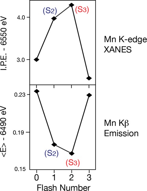
Mn K-edge inflection points from the XANES spectra (Figure 23) and the first moments from the Kβ1,3 spectra (Figure 24) shown on top and bottom, respectively. The inflection points and the first moments show that the oxidation of the OEC from the S0 to S1 and S1 to S2 is different from the S2 to S3 advance. Adapted from ref (146).
One point to consider is whether major structural changes can cause the lack of an energy shift in the XES data, even when there is a Mn-centered oxidation state change. A detailed understanding of Kβ1,3 XES requires a ligand-field multiplet theory that considers symmetry-dependent perturbations such as (1) spin–orbit coupling, (2) ligand-field splitting, (3) Jahn–Teller distortion, and (4) spin–spin interaction between different metal atoms.195 Each of these perturbations will split the spin states into a multiplet of states, causing an asymmetric broadening of the observed emission peaks, indicating that there is some dependence of the Kβ1,3 XES spectra on the ligand environment. Although it is expected to be subtle, the details of such effects need to be further investigated.
4.3.2. Resonant Inelastic X-ray Scattering
The electronic structure of the Mn complex in PS II has been studied in detail using RIXS, owing to the developments in the instrumentation for conducting such two-dimensional X-ray spectroscopy experiments. The potential of the RIXS methodology for understanding the details of electronic structure of the Mn4CaO5 cluster has been demonstrated using comparisons to Mn complexes that are very basic such as oxides and mononuclear Mn coordination complexes in different oxidation states, and more recently using other Mn complexes with oxo-bridged multinuclear structures in various oxidation states.
The RIXS contour plots of the simpler types of Mn compounds, the oxides of Mn and mononuclear coordination compounds of Mn, which are all 6-coordinate with formal oxidation states, Mn(II), Mn(III) and Mn(IV) are shown in Figure 26A, B. Despite the differences in the ligand environment, similar trends are observed in the Mn oxides and the mononuclear coordination compounds with the same oxidation states. The spectrum from Mn(II)O shows one broad peak centered at ∼6540 eV that is well-explained by the contribution of the crystal field splitting between the t2g and eg orbitals.196 For Mn in oxidation state (III) and Mn(IV), the electron (3d-3d) interaction becomes dominant. In Mn(III) compounds, for example, the two strong resonances observed in the contour plots (ν = 6540 and 6543 eV) are due to the (3d, 3d) multiplet interactions (∼3 eV separation). The separation of two strong features is smaller in Mn coordination compounds (∼2 eV) due to the reduced magnitude of the (3d-3d) interaction; i.e., a more covalent electron configuration decreases the electron–electron interaction.
Figure 26.
Contour plots of the 1s2p3/2 RIXS planes for four Mn oxides (A) in oxidation states II, III, and IV and the four molecular complexes (B) MnII(acac)2(H2O)2, MnIII(acac)3, [MnIII(5-Cl-Salpn)(CH3OH)2]+, and MnIV(sal)2(bipy).233,234 The abscissa is the excitation energy, and the ordinate is the energy transfer axis. (C) Line plots extracted from the RIXS planes for the coordination complexes in oxidation states III or IV and the S1 state of PS II. The PS II plots are between oxidation states III and IV. An integration of the 2D plot parallel to the ordinate yields L-edge like spectra, the feature at ∼640 eV corresponds to transitions to J = 3/2 like states (L3 edges). Integrations parallel to the energy transfer axis sort the spectrum according to the final state. Adapted from ref (196).
For Mn coordination compounds, the energy position shifts more toward lower energy compared to the Mn oxides (Figure 26B), which indicates that Mn coordination compounds have much stronger covalency compared to the Mn oxides. The changes per oxidation state in the positions are more pronounced between the Mn oxides than are those between the Mn coordination compounds.
In Figure 26C, the two types of line plots (constant incident energy (CIE, left) and constant energy transfer (CET, right)) of the PS II S1 state are shown together with those of Mn coordination compounds. The S1 CET spectrum shows mixed features characteristic of Mn(III) and Mn(IV) compounds, having two main peaks, which supports the mixed oxidation states of Mn(III) and Mn(IV) in the S1 state assigned earlier by the EPR and XANES studies.
More recently, RIXS has been used to study the entire S-state cycle to specifically address the issue of the electronic structure of the S3 state.197 Figure 27 shows Mn XAS pre-edges and RIXS spectra of the S0 to S3 states of PS II. RIXS spectroscopy considerably improves the pre-edge separation from the main edge feature as compared to XANES in which it is usually difficult to distinguish the contribution of strong main edge transition. The main spectral features in the RIXS spectra extend along a diagonal streak in the 1s2p RIXS plane. Spectral features off this diagonal line result from different interactions of the 1s and the 2p core hole with the valence electrons. These direct Coulomb and exchange interactions are considerably stronger for a 2p core hole, making the technique also sensitive to the spin density of Mn.
RIXS spectra of a series of multinuclear Mn model complexes are shown in Figure 28 to compare with the S3 state spectrum.196−199 The Mn(IV) complexes show a characteristic off-diagonal intensity, suggesting a stronger (2p, 3d) final-state interaction. Strong variations are seen in the electronic structure within the series of MnIV model systems. The spectrum of the S3 state best resembles the MnIV complexes, Mn3IVCa2 and saplnMn2IV (OH)2, i.e., the oxo-bridge protonation of Mn dimer complexes and the presence of Ca in one corner of a Mn cubane structure show a similar spectroscopic response, suggesting that Ca in PS II and protonation of the oxo-bridge may give rise to analogous modifications of the electronic structure at the Mn sites, e.g., ligand symmetry changes. These results emphasize that the assignment of formal oxidation states alone is not sufficient for understanding the detailed electronic structural changes and describing the complex nature of the electronic structure in multinuclear clusters like the Mn4CaO5 cluster in PS II. The Mn RIXS spectral changes are subtle during the S-state transitions (Figure 27), which suggests that electrons are strongly delocalized in the Mn4CaO5 cluster, and ligands may be intimately involved in the redox chemistry.
Figure 28.
Contour plots of Mn 1s2p RIXS planes of model compounds (a) salpn2MnIV2(OH)2, (b) salpn2MnIV2(O)(OH), (c) salpn2MnIV2(O)2, (d) phen4MnIV2(O)2, (e) MnIV3Ca2, and (f) MnIV3(O)4Acbpy.76,88,235,236 The spectral features in (a), (b), and (e) with protonated bridge or with Ca are more similar to PS II S3 state spectra shown in Figure 27. Detailed theoretical analysis of spectra from model compounds such as these has the potential for understanding the electronic structure and the changes in PS II. Adapted from ref (197).
4.4. S-States and Summary of the Oxidation States
Current understanding of the oxidation state changes of the Mn4CaO5 cluster during the reaction cycle is a stepwise oxidation of Mn in each S-state transition; within the context of the formal oxidation state, the Mn oxidation state could be assigned as Mn(III3, IV) for S0, Mn(III2, IV2) for S1, Mn(III, IV3) for S2, and Mn(IV4) for S3. The RIXS study, however, suggests that formal oxidation states may be insufficient for describing the complex nature of the electronic structure in multinuclear clusters like the Mn4CaO5 cluster in PS II, and that electrons are strongly delocalized in the Mn4CaO5 cluster. It is likely that ligands are intimately involved in modulating the redox chemistry and are also involved in the delocalization of the electron density as the cluster is oxidized.
The RIXS data show that, among the compounds with the same formal oxidation states, the spectroscopic response is modulated by the delocalization of the charge density. This is illustrated by the differences in the RIXS spectra of the oxides and the coordination complexes. The trend is that, for similar oxidation states, the charge distribution as determined by the RIXS spectra seems to be higher in the Mn4Ca cluster than in coordination complexes, and higher in coordination complexes than in oxides. Therefore, the data from PS II suggest that the distribution of the charge between the metal and ligands could be critical for the mechanism of water oxidation.
Of the two main mechanisms that are being considered for the O–O bond formation catalyzed by the OEC, one involves the generation of a MnV-oxo group in the final step when the O–O bond is formed, and the alternate mechanism involves the oxo-oxyl bond formation.71,200 The current RIXS results show that the change of the electronic charge includes the ligands in all S-state transitions, and such delocalization of charge on the ligands may play an important role in the reaction. However, interpretation of the electronic structure of the Mn4CaO5 cluster beyond the formal oxidation state requires chemical structural information of the cluster in each S-state, as well as further development of theoretical tools to interpret the spectroscopic data, and such efforts are underway. Additionally, whether or not Ca plays a role in modulating the redox-active cluster is still an open question, but recent studies with heteronuclear Mn and Ca/Sr complexes have implicated the role of Ca in this process.87
4.5. Lessons from XES of Model Complexes about the Intermediate States
4.5.1. High-Spin and Low-Spin MnV with Kβ1,3/Kβ″ Spectra
Mn(V) has been proposed as a possible transient intermediate in the water oxidation in PS II as well as some of the Mn-based catalytic reactions like epoxidation reactions and C–H bond functionalization. Mn(V)-oxo complexes have been synthesized, and most of them are stable at room temperature, with low-spin S = 0 ground states.201−203 On the other hand, there are only a few reports on high-spin Mn(V)-oxo species with S = 1 spin ground states, one with a porphyrin ligand204 and another that has trigonal symmetry.89 The metal–oxo interactions in trigonal symmetry are weaker compared to those with tetragonal symmetry, rendering the Mn(V)-oxo species with high-spin configuration. This species is unstable at room temperature and more reactive.89 We would therefore expect a high-spin, reactive Mn(V) to be involved in the catalytic reaction if indeed a Mn(V) is involved in the O–O bond formation in the OEC. It is known that up to the S3 state all four Mn are in a high-spin configuration; hence, it is likely that if Mn(V) is involved it would also be high spin.
The high-spin mononuclear Mn(V) complex recently prepared by the Borovik group is 5-coordinate.89 It is very reactive and short-lived at room temperature, and therefore can be studied only at low temperature. It is likely that having a 5-coordinate geometry is required to generate a high-spin Mn(V) species. The Mn XAS and Kβ1,3/Kβ′ XES of this complex can be a good indicator of identifying low/high-spin Mn species as well as the presence or absence of the Mn(V) species (Figure 29).89
Figure 29.
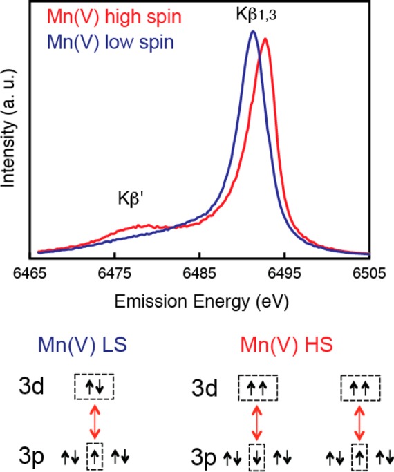
Mn Kβ1,3 and Kβ′ spectra from the high-spin and low-spin Mn(V) complexes.89,202 The exchange coupling scheme describing the two cases is shown below the spectra, which explains the lack of a Kβ′ peak in the low-spin case and the energy difference in the Kβ1,3 peak between the low- and high -pin complexes. Adapted from ref (89).
4.5.2. XES for Direct Detection of Oxo-Bridges Using Kβ2,5/Kβ″ Spectra
Direct detection of O-ligation to the Mn4CaO5 cluster provides a method for studying the role of the O ligands in the mechanism of water oxidation and dioxygen formation. However, there are few, if any, methods that can specifically monitor the electronic spectra of the O ligand atoms of Mn from the Mn4CaO5 cluster in the PS II complex. Kβ2,5 emission is predominantly from ligand 2p (metal 4p) to metal 1s, and the Kβ″ emission is assigned to a ligand 2s to metal 1s, known as crossover transitions.205−207 Therefore, only direct ligands to the metal of interest are probed with Kβ,2,5/Kβ″ emission. In particular, the Kβ″ energy is affected by the charge density on the metal, the ligand protonation state, and changes in the coordination environment. The intensity is influenced by the overlap between the Mn 3d and ligand molecular orbital wave functions and is thus affected by the metal-to-ligand distance, as well as the number of ligands per metal ion. Shorter distances (e.g., from higher bond order or deprotonation) result in increased Kβ″ intensity with an approximate exponential dependence.205 On the other hand, a spread of the molecular wave function over next-nearest neighbor atoms will decrease the Kβ″ spectral intensity. Therefore, contribution from single atom ligands such as oxo-bridges, or terminal oxo ligands bonded to Mn, is predominant. These combination of factors makes the Kβ″ spectrum a powerful tool for detection and characterization of oxo-bridges in the Mn4CaO5 cluster of PS II.208
Figure 30 shows a comparison of the PS II S1 state spectrum with those of a series of Mn coordination compounds, MnV-oxo (a), di-μ-oxo bridged Mn2III,IV and Mn2IV (b, c), cubane-type Mn2IIIMn2IV and MnIIIMn3IV (d, e), and a μ-alkoxide bridged Mn2II (f). These compounds have oxo-bridged Mn (except for MnV-oxo) with O or N/O terminal ligands. The strongly delocalized molecular orbitals from O and N terminal ligands, and the μ-alkoxide/carboxylate bridges, do not contribute significantly to the spectra. Moreover, terminal ligands are generally at longer distances to Mn than the bridging ligands, and their contributions are smaller.205 There is a strong peak in the MnV-oxo compound, indicating that the Kβ″ peak intensity is predominantly sensitive to single atom ligands and short metal–ligand atom distances, namely, bridging O ligands and double/triple bonds, which all have localized 2s orbitals. The sensitivity of the spectra to even one-electron changes is illustrated in Figure 30. The spectra are different for the two binuclear and the two cubane molecules in which one of two or four Mn is oxidized from (III) to (IV). The Kβ″ peak of the PS II S1 state is relatively intense compared to other Mn2III,IV di-μ-oxo bridged compounds. This suggests that there are several μ-oxo bridged Mn–O bonds in the S1 state.14
Figure 30.
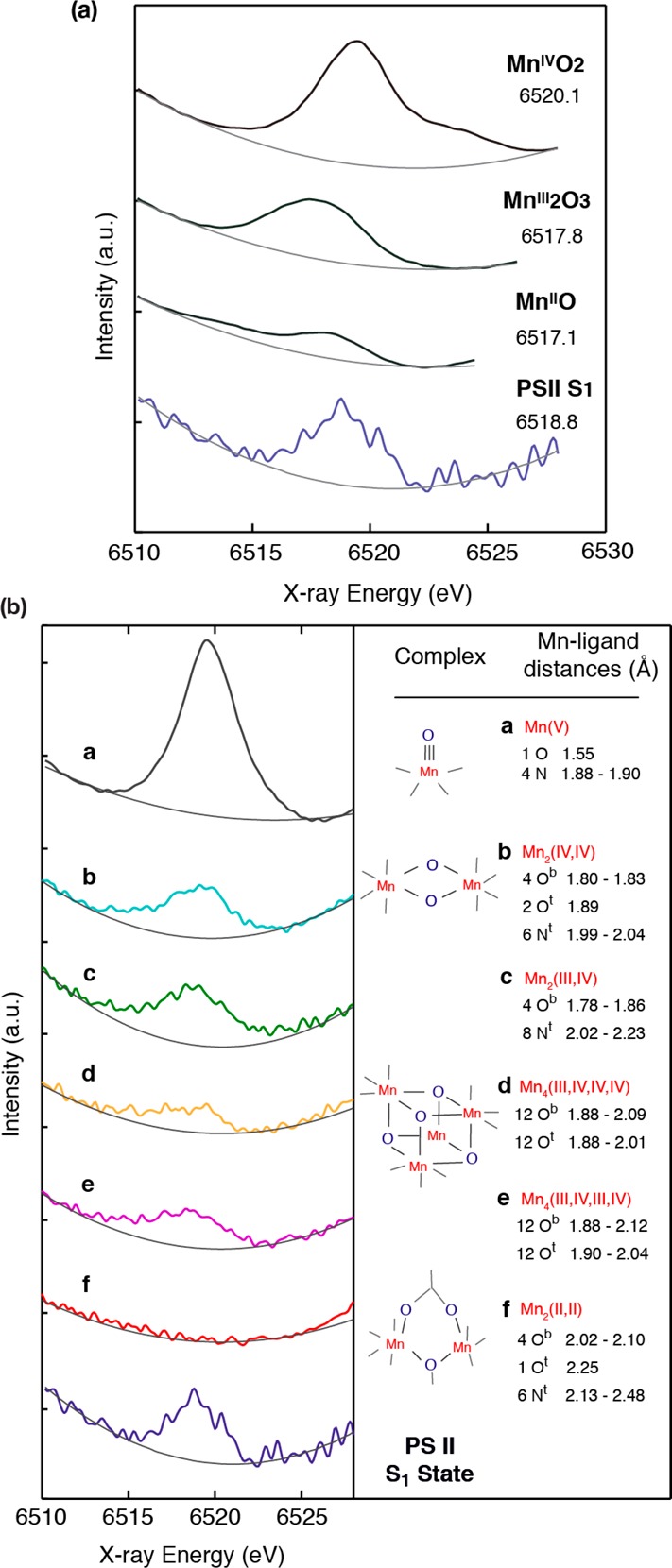
(a) Kβ′′ of the Mn in oxidation states II, III, and IV is compared to PS II in the S1 state. The position of the peak in the S1 state shows that the oxidation state is III2,IV2, and the intensity as exemplified in (b) by comparison to Mn complexes makes it clear that it is from an oxo-bridged Mn. The Mn model compounds were the following: a bridging μ-alkoxide Mn2 compound237 ([Mn2(II)μ-ClCH2CO2](CH3CO2)2(ClO4)2), two di-μ-oxo bridged Mn2 compounds238,239 ([Mn2(III,IV)O2bipy4](ClO4)3 and [Mn2(IV,IV)O2terpy2(SO4)2]6(H2O)), two Mn4 cubane compounds240 (hexakis(μ2-diphenylphosphinato)tetrakis(μ3-oxo)Mn4(III,III,IV,IV) and [hexakis(μ2-diphenylphosphinato)tetrakis(μ3-oxo)Mn4(III,IV,IV,IV)]CF3SO3), and a macrocyclic Mn(V)-oxo complex.202 Adapted from ref (208).
The involvement of bridging oxo groups13 or the high-valent MnIV=O• or MnV≡O species23,209 has been implicated in the mechanism for the formation of the critical O–O bond in the water-oxidation reaction of PS II. It is feasible to obtain Kβ2,5/Kβ″ spectra for the Mn4CaO5 cluster in PS II, and the outlook for Kβ2,5/Kβ″ spectroscopy as a tool for studying the nature of the O ligand binding modes and, therefore, the mechanism of the water-splitting reaction seems promising.
4.5.3. Protonation State of the Oxo-Bridges with Kβ2,5/Kβ″ Spectra
Protonation of the oxo bridges is another issue where the study of model complexes using Mn Kβ2,5/Kβ″ XES has the potential for being useful for understanding the OEC. In PS II, protonation state changes in the bridging oxygen (μ-oxo or μ-hydroxo) and/or a terminal substrate water as aqua or hydroxo have been proposed during the four-electron redox chemistry.71,210,211 The generally accepted proton-release pattern during the S0 to S1, S1 to S2, S2 to S3, and S3 to S0 transitions is 1, 0, 1, 2, respectively,212 although it has been reported that the proton-release pattern is pH-dependent.162
Several techniques have the potential to detect a single protonation event, while few of them can directly and selectively probe the protons in the first coordination sphere of a transition metal ion. Potential methods include vibrational spectroscopy and ligand-sensitive EPR techniques such as ENDOR (electron nuclear double resonance), ESEEM (electron spin echo envelope modulation), and HYSCORE (hyperfine sublevel correlation). EXAFS can also provide indirect information about protons, by the effect that protonations or deprotonations might have on the Mn–Mn/Sr(Ca) and Mn–O,N ligand atom distances.
The shortening of one Mn–Mn distance observed in the EXAFS during the S0 to S1 transition could be a consequence of the deprotonation of an hydroxo (OH–) bridge between Mn atoms to an oxo (O2–) bridge.47,76 The S0 to S1 transition is accompanied by the release of one proton from the OEC. During the S1 to S2 transition, there is no net release of protons and there are no significant changes in Mn–Mn/Ca distances. The following S2 to S3 state transition is accompanied by the release of a proton, and a structural change in the cluster is observed. There are no EXAFS studies on intermediate states between S3 and S0, when two protons are released. Ca can accommodate 7 or 8 ligands, and it is therefore ideally suited for ferrying in H2O/OH– groups to the catalytic site (Hillier and Messinger in ref (9)).
Unlike EXAFS, the Kβ2,5/Kβ″ XES can be a direct method to probe single protonation events or other changes in ligand environment. The advantage of this method over EPR techniques is its element specificity, and they are sensitive only to the protonation states of the ligands of metals. Moreover, they are unrestricted by the spin states of the compounds.
A set of homologous dinuclear MnIV complexes (Figure 31a) that were initially synthesized by Baldwin et al.,76 in which the protonation state of the bridging oxygen atoms was changed systematically, has been explored. Although these complexes are not mimics of the Mn4Ca cluster in the OEC, they contain motifs such as oxo and protonated oxo-bridges that are implicated in the mechanism of water oxidation. A combination of XES data (Figure 31b) and DFT calculations (Figure 31c)213 provides a detailed understanding of the origin of valence-to-core emission peaks, making XES an important tool to resolve protonation states of bridging oxygen atoms in biological catalysts. The technique also allows one to differentiate between two possible structures for the doubly protonated species, namely, a bis-μ-hydroxo versus a μ-oxo-μ-aqua bridged complex. Although a symmetric doubly protonated bridging motif is chemically more reasonable, the ability of valence-to-core XES and the accompanying DFT calculations to distinguish between these isomers is of interest, as such aquo units have been formulated recently as bridging motifs for the Mn4CaO5 core of the OEC.214
Figure 31.

Sensitivity of the Kβ2,5 and Kβ′′ spectra to the protonation state. This is demonstrated in the spectra of three Mn2IV oxygen-bridged complexes in which the protonation states of oxo-bridges are changed. (a) 1 and 2 show the structures of the di-μ-oxo and oxo-hydroxo bridged complexes, and 3a and 3b show the two possibilities, dihydroxo or oxo-aquo bridges. (b) Spectra of 1, 2, and 3 shown in solid black, dashed red, and dashed blue, respectively. (c) Assignments of the calculated XES valence-to-core region based on the orbital character corresponding to the individual transitions for compounds 1, 2, 3a and 3b shown in (a). The left side shows the Kβ″ region, and the right side shows the Kβ2,5 region. Adapted from ref (241).
While detecting very weak valence to core Kβ2,5/Kβ″ XES signals is challenging in the dilute biological samples, recent progress in the design of the spectrometer and the high brilliance available at third-generation synchrotron facilities make it possible to detect such weak signals, and the effort is underway.
5. Current Understanding of the Water-Oxidation Mechanism
There is limited direct experimental information about the O–O bond-formation step, and the mechanisms that have been proposed are largely based on what is known about the structures in the stable S-states and theoretical calculations.71,85,215−217 There is consensus that the O–O bond is not formed before the S3 state. It is thought that, after the third flash, one electron and one proton is released from the S3 state, forming the putative S4 state where the O–O bond is formed prior to the release of molecular oxygen.162,218 The presence of a kinetic intermediate, S3Yz•, before the final oxidation of the OEC (S4) has been reported from several experiments based on the detection of a lag phase (150–200 μs): UV–vis133,219 and EPR spectroscopy220 by following Yz• kinetics, time-resolved XAS by following the Mn oxidation state,157 and FTIR spectroscopy.153 It is proposed that, at this stage, the OEC is not oxidized, but an electron is released from Yz, and the OEC is oxidized only after a release of proton in the S4 state. The chemical nature of the transient S4 state has not yet been experimentally determined.
Since the 1.9 Å crystal structure was reported in 2011, it has become possible to interpret the various experimental data within the context of the reliable geometric structure of the Mn4CaO5 cluster.221 Although there are questions about the chemical nature of the cluster such as the protonation state of the bridging oxygens and the identity of the terminal ligands such as aquo or hydroxo, it is now possible to narrow down the many proposed water oxidation mechanisms and the probable site on the Mn4CaO5 cluster. The O–O bond formation mechanisms proposed thus far are shown in Figure 32: (a) nucleophilic attack (high-valent Mn(V)-oxo or Mn(IV)-oxo);85,209,210,222−224 (b) between two oxo-bridges;13 (c) terminal oxo-radical and bridging oxygen;23,24,71 and (d) two terminal oxygen ligands.217 A radical coupling mechanism (e) has been suggested for a Ru catalyst, although not for the OEC in PS II.225
Figure 32.
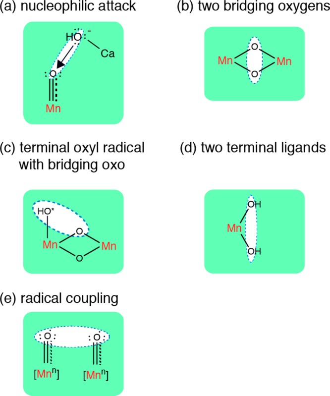
Main mechanistic schemes that are being considered for the O–O bond formation by the Mn4CaO5 cluster.
Among these mechanisms, the most likely one suggested from the substrate water exchange studied by TR-MIMS (time-resolved membrane inlet mass spectroscopy) using isotope-labeled water is (c) the oxo/oxyl radical coupling mechanism. The isotope-labeled water-exchange studies have provided important information that informs about the possible O–O bond-forming mechanisms.226,227 From the distinct exchange rate of the two substrate water molecules, Wf (fast-exchanging water) and Ws (slow-exchanging water), at each S-state, as well as currently available structural information and the EPR results,228 Messinger et al. suggested that Wf is the bridging oxygen, O5 (Figure 6), which reacts with a terminal oxyl radical formed in the S4 state that is bound to either Mn1 or Mn4. A detailed review by Cox and Messinger is found in the literature.25 This mechanism is basically in line with what Siegbahn has suggested based on theoretical calculations.71
RIXS results described in section 4.3.2 have shown that the electrons are strongly delocalized in the Mn4CaO5 cluster, and if so, ligands may be intimately involved in the redox chemistry. This suggests that such delocalization may play a role during the O–O bond-formation step in the S4 state. The structural changes that occur in the S2 to S3 transition described in section 3.2.3 show that, accompanying both Mn–Mn and Mn–Ca(Sr) distance changes, the closed cubane structure may be formed in the S3 state. If such a structural change occurs, it will affect the charge distribution in the OEC.
In the oxo/oxyl mechanism proposed on the basis of the substrate water-exchange results, redox tautomerism in the S1, S2, and S3 states is suggested to play an important role for the fast water-exchange rate.24,229 Although such interconvertible multistates are observed in the S2 state (g = 2 and g = 4 spin states), there is no experimental evidence so far in the S1 and the S3 states, and further structural study is necessary. The presence of such multistates also implies the importance of the dynamic nature of the metal cluster to the catalytic function. Therefore, it becomes important to study the structural and chemical dynamics of the Mn4CaO5 cluster and PS II under functional conditions, which is the future direction using XFELs; the approach is described in the next section.
6. Toward an Understanding of Protein and Chemical Dynamics of PS II
Synchrotron radiation (SR)-based X-ray techniques (crystallography and spectroscopy) have been the major tools for studying the architecture of PS II and its water-oxidation reaction in the OEC. As described above, X-ray spectroscopy has provided the element-specific information of structural and electronic structure of the cryo-trapped intermediate S-states, from the S0, S1, S2 to S3 state. However, accessing the kinetically unstable S4 state (Figure 1) that appears in the last step of the catalytic cycle is difficult using the traditional cryo-trapping methodology, and characterizing the nature of such a transient state requires time-resolved detection at room temperature. Within the total time scale of ∼1.3 ms of the S3–S4–S0 transition after initiation by the third flash, sequential events occur that include release of one electron, release of two protons, release of molecular oxygen, and water substrate(s) binding, along with four-electron reduction of Mn. Understanding the nature of the S4 state and following the sequential chemistry during the S3–S4–S0 transitions is therefore at the heart of understanding the water-splitting mechanism. Additionally, how the protein environment cooperates with this catalytic reaction by providing the environment for stabilizing the wide range of Mn redox states, reassembling the cluster with two water molecules, and providing a pathway for protons, water, and oxygen are the key questions for understanding the mechanism of this metalloenzyme. Recent development of femtosecond XRD58 with its “collect before destroy” approach opens a new way of studying the structural dynamics of enzyme systems under functional conditions at ambient conditions. The very short, intense fs pulses make it possible to outrun damage and collect data. This method also makes simultaneous data collection of XRD and X-ray spectroscopy possible as shown in Figure 33.
Figure 33.
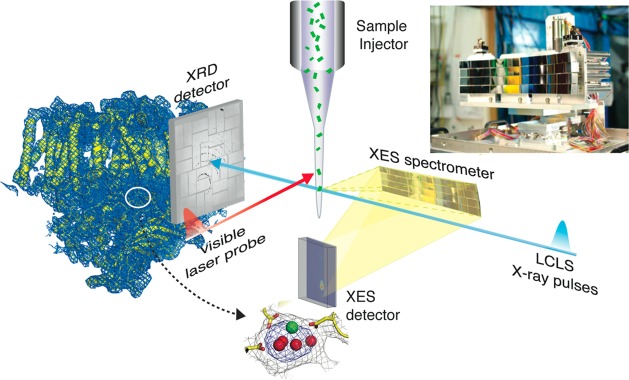
Schematic of the simultaneous detection of X-ray diffraction and X-ray emission spectra of photosystem II crystals using the femtosecond pulses from a X-ray free electron laser (XFEL) at room temperature. The ultrashort, intense pulses from the XFEL allow one to collect data at room temperature without radiation damage, thus opening up possibilities for conducting time-resolved studies. The crystal suspension is injected using a microjet that intersects the X-ray pulses. XRD data from a single crystal are collected downstream, and XES data from the same crystal are collected at ∼90° to the beam using an XES spectrometer and a position-sensitive detector. A visible laser (527 nm) is used to illuminate the crystals to advance the PS II crystals through the S-states.
Simultaneous data collection of XRD and X-ray spectroscopy has several important advantages; the method probes the overall protein structure from XRD and the electronic structure of the Mn4CaO5 cluster in the oxygen-evolving complex from the spectroscopic data using the same samples under the same conditions. This eliminates the controversy that often exists between the spectroscopic and XRD results due to the different experimental conditions and the different sensitivity and error of each method. The use of the X-ray free electron laser (XFEL) pulses is critical for this approach.
Among the various spectroscopic methods, nonresonant XES probes occupied electronic levels. In particular, the Kβ1,3 and Kβ′ lines are a probe of the number of unpaired 3d electrons, hence providing information about the oxidation and/or spin state. Experimentally, XES using an energy-dispersive X-ray spectrometer230 is well-suited for such combined shot-by-shot studies, as excitation energies above the 1s core hole of first-row transition metals are also ideal for XRD, and therefore neither incident nor emitted photon energy have to be scanned.231
Simultaneous XRD/XES data were collected from microcrystals of PS II. Figure 34 shows the electron density map of PS II isolated from the thermophilic cyanobacterium T. elongatus, collected at Linac Coherent Light Source (LCLS) using the single-shot approach. The data is comparable to that obtained using synchrotron radiation studies as seen by the similarities in the overall structure of the helices, the protein subunits, and the location of the various cofactors.
Figure 34.
PS II structure from diffraction of micrometer-sized crystals using ∼50 fs X-ray pulses at room temperature at the XFEL. (a) Electron density map, 2mFo-DFc, for the PS II in the S1 state shown in yellow, and the electron density contoured at 1.2 σ (blue mesh) shown for a radius of 5 Å around the protein. (b) Detail of the same map in the area of the Mn4CaO5 cluster in the dark S1 state, with mesh contoured at 1.0 σ (gray) and 4.0 σ (blue). Selected residues from subunit D1 are labeled for orientation; Mn is shown as violet spheres, and Ca is shown as as an orange sphere (metal positions taken from pdb file 3bz1). (c) (Left) Kβ1,3 X-ray emission spectra from crystals (red dashed) and solutions (green) of PS II at room temperature using the XFEL. (Right) Kβ1,3 X-ray emission spectra of PS II solutions in the S1 state collected at the XFEL at room temperature (green), spectra collected using synchrotron radiation under cryogenic conditions with low dose (“8K intact”, light blue) and using synchrotron radiation at room temperature under high-dose conditions (“RT damaged”, pink). The spectrum from MnIICl2 in aqueous solution collected at room temperature is shown (gray) for comparison. The XES spectra show that the Mn4CaO5 cluster is intact in the crystals under the conditions of the XFEL experiment. Adapted from ref (62).
At the published resolution of 5.7 Å, there are no large protein structural changes taking place between the S1 and S2 states.61,62 The isomorphous difference map computed between the dark and illuminated data set, contoured at ±3.0 σ, showed no significant peaks above the noise level in the region of the Mn4CaO5 cluster and the stromal electron-acceptor side of the complex. Although the S1–S2 transition is accompanied by a number of changes in carboxylate and backbone vibration frequencies as detected by infrared spectroscopy,31,152,232 the associated structural changes are most likely too small to be detected by the resolution achieved in the present study of ∼5 Å (Figure 35).
Figure 35.
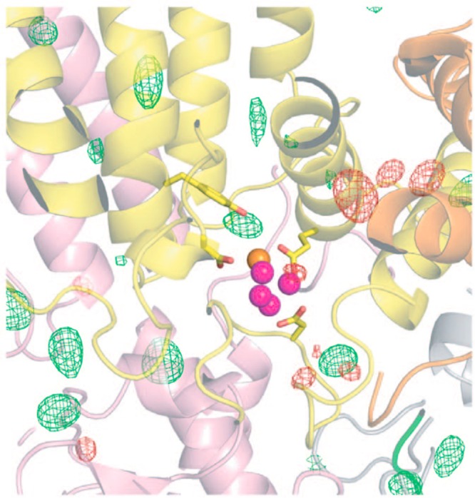
First data from the S1 and illuminated S2 state using the femtosecond pulses from the XFEL. This experiment shows that time-resolved crystallography of PS II at room temperature is possible. Isomorphous difference map between the XFEL-illuminated (S2 state) and the XFEL-dark (S1 state) XRD data set in the region of the Mn4CaO5 cluster, with Fo–Fo difference contours shown at +3 s (green) and −3 s (red); analysis indicates that this map is statistically featureless showing that at this resolution there are no major changes in the protein or the metal ion positions. Metal ions of the Mn4CaO5 cluster are shown for orientation as violet (Mn) and orange (Ca) spheres; subunits are indicated in yellow (D1), orange (D2), pink (CP43), and green (PsbO). Adapted from ref (62).
This technique can be used for future time-resolved studies of light-driven structural changes within proteins and cofactors, and of chemical dynamics at the catalytic metal center under functional conditions.
7. Conclusions
Since the insightful hypothesis of the S-state intermediates in the process of the water oxidation reaction by Bessel Kok in the 1970s, which were based on the kinetics of dioxygen release as a function of flash number, we are now in a position to look into the mechanism of the catalytic machine. One of the major advances has been the developments in the field of X-ray crystallography that have now revealed the structure of PS II and the Mn4CaO5 cluster at very high resolution. In conjunction, the developments in X-ray spectroscopy techniques have contributed to revealing both the geometric and electronic structure of the Mn4CaO5 cluster, not only in the native dark state but also in the other intermediate states. EPR and FTIR spectroscopy have also been instrumental in advances that have led to mapping the geometric structures obtained from X-ray spectroscopy and crystallography on to the electronic structures of the native and intermediate states. All of above techniques are taking advantage of the biochemical advancements that have been able to isolate and characterize ever purer PS II solution and crystal samples. We also note the importance of the availability of appropriate inorganic model complexes that are critical for the interpretation of the spectroscopic data as well as theoretical developments.
In concluding our last review in Bioinorganic Enzymology I, we noted some of the questions about the OEC that needed to be answered. Some of these, especially the question about what is the structure of the Mn4CaO5 cluster in the dark native state, may be approaching final resolution. However, there are some critical questions that are still open. What is the structural or mechanistic role of Ca2+ and how is Cl– involved in maintaining a high level of activity? What are the oxidation states and the structure of the Mn cluster in the transient S4 state? How are the oxygen atoms coupled to form an O–O bond? In spite of many interesting leads and studies, the S3 → (S4) → S0 process has not yet been understood in detail. These questions, along with the need to characterize the proposed transient S4 state and other kinetic intermediates that may be present, offer challenges for the future; they need to be addressed before we can fully understand where and how plants oxidize water to dioxygen.
Finally, the studies in the natural photosynthetic water oxidation reaction have had a profound influence and inspiration on the development of artificial water-oxidizing catalysts. Given the vision of a renewable energy economy, understanding the design principles of the natural water oxidation reaction could be of great practical use to create an artificial photosynthetic device and for developing cleaner, renewable carbon-neutral energy sources.
Acknowledgments
The research presented here was supported by the Director, Office of Science, Office of Basic Energy Sciences (OBES), Division of Chemical Sciences, Geosciences, and Biosciences of the Department of Energy (DOE) under Contract DE-AC02-05CH11231, and by the NIH Grant GM 55302. X-ray facilities were provided by the Stanford Synchrotron Radiation Laboratory (SSRL) and the Linac Coherent Light Source (LCLS) at Stanford, the Advanced Light Source (ALS) at Berkeley, and the Advanced Photon Source (APS) at Argonne, all funded by DOE OBES. We are grateful to our present and past group members and all our collaborators, who contributed to the research presented in this review. We thank Jan Kern and Johannes Messinger for many discussions concerning the structure of the Mn4Ca cluster and the mechanism of water oxidation in PS II.
Biographies

Junko Yano received a B.A. degree in Applied Biological Science from Hiroshima University, Japan, an M.Sc. from Graduate School of Biosphere Science, Hiroshima University, Japan, and a Ph.D. in Physical Chemistry from Osaka University, Japan, in 1999. She has received several awards including the Golda Meir Research Fellowship from Hebrew University in Jerusalem and the Robin Hill Award by the International Society for Photosynthesis Research. She is currently a Staff Scientist at the Physical Biosciences Division at Lawrence Berkeley National Laboratory. She is also a PI of the Joint Center for Artificial Photosynthesis at Berkeley. Her research areas include the water oxidation in natural photosynthesis and artificial photosynthesis, catalytic reactions in metalloenzymes, and application of synchrotron X-ray radiation and X-ray free electron laser techniques to biological and inorganic systems.

Vittal Yachandra received his B.Sc. degree in Chemistry from Loyola College, University of Madras, and M.Sc. degree in Chemistry from the Indian Institute of Technology at Kanpur, India. In 1975 he moved to the U.S. and received his M.S. from the University of Chicago and his Ph. D. from Princeton University in 1982, working with Prof. Thomas Spiro on resonance Raman spectroscopy of iron–sulfur proteins and X-ray spectroscopy of Zn and Co carbonic anhydrase. Photosynthetic water oxidation and the Mn4Ca catalytic cluster became his research interests, when he moved as a postdoctoral fellow working with Drs. Melvin Klein and Kenneth Sauer at the Melvin Calvin Laboratory, Lawrence Berkeley National Laboratory, in 1982, where he became a Staff Scientist in 1985. Since then his research has focused on the use of X-ray spectroscopy and EPR to study the Mn4Ca water-oxidizing catalyst in photosynthesis. He is presently a Senior Scientist in the Physical Biosciences Division at the Lawrence Berkeley National Laboratory at Berkeley.
The authors declare no competing financial interest.
Funding Statement
National Institutes of Health, United States
References
- Williamson A.; Conlan B.; Hillier W.; Wydrzynski T. Photosynth. Res. 2011, 107, 71. [DOI] [PubMed] [Google Scholar]
- Bekker A.; Holland H. D.; Wang P. L.; Rumble D.; Stein H. J.; Hannah J. L.; Coetzee L. L.; Beukes N. J. Nature 2004, 427, 117. [DOI] [PubMed] [Google Scholar]
- Des Marais D. J. Science 2000, 289, 1703. [PubMed] [Google Scholar]
- Blankenship R. E.; Hartman H. Trends Biochem. Sci. 1998, 23, 94. [DOI] [PubMed] [Google Scholar]
- Allen J. F.; Martin W. Nature 2007, 445, 610. [DOI] [PubMed] [Google Scholar]
- Johnson J. E.; Webb S. M.; Thomas K.; Ono S.; Kirschvink J. L.; Fischer W. W. Proc. Natl. Acad. Sci. U. S. A. 2013, 110, 11238. [DOI] [PMC free article] [PubMed] [Google Scholar]
- Anbar A. D.; Duan Y.; Lyons T. W.; Arnold G. L.; Kendall B.; Creaser R. A.; Kaufman A. J.; Gordon G. W.; Scott C.; Garvin J.; Buick R. Science 2007, 317, 1903. [DOI] [PubMed] [Google Scholar]
- Sauer K.; Yachandra V. K. Proc. Natl. Acad. Sci. U. S. A. 2002, 99, 8631. [DOI] [PMC free article] [PubMed] [Google Scholar]
- Photosystem II: The Light-Driven Water:Plastoquinone Oxidoreductase; Wydrzynski T., Satoh S., Eds.; Springer: Dordrecht, The Netherlands, 2005. [Google Scholar]
- Lewis N. S.; Nocera D. G. Proc. Natl. Acad. Sci. U. S. A. 2006, 103, 15729. [DOI] [PMC free article] [PubMed] [Google Scholar]
- Eisenberg R.; Gray H. B. Inorg. Chem. 2008, 47, 1697. [DOI] [PubMed] [Google Scholar]
- Blankenship R. E.; Tiede D. M.; Barber J.; Brudvig G. W.; Fleming G.; Ghirardi M.; Gunner M. R.; Junge W.; Kramer D. M.; Melis A.; Moore T. A.; Moser C. C.; Nocera D. G.; Nozik A. J.; Ort D. R.; Parson W. W.; Prince R. C.; Sayre R. T. Science 2011, 332, 805. [DOI] [PubMed] [Google Scholar]
- Yachandra V. K.; Sauer K.; Klein M. P. Chem. Rev. 1996, 96, 2927. [DOI] [PubMed] [Google Scholar]
- Yano J.; Yachandra V. K. Inorg. Chem. 2008, 47, 1711. [DOI] [PMC free article] [PubMed] [Google Scholar]
- Dau H.; Zaharieva I.; Haumann M. Curr. Opinion Chem. Biol. 2012, 16, 3. [DOI] [PubMed] [Google Scholar]
- Zouni A.; Witt H.-T.; Kern J.; Fromme P.; Krauß N.; Saenger W.; Orth P. Nature 2001, 409, 739. [DOI] [PubMed] [Google Scholar]
- Kamiya N.; Shen J. R. Proc. Natl. Acad. Sci. U. S. A. 2003, 100, 98. [DOI] [PMC free article] [PubMed] [Google Scholar]
- Ferreira K. N.; Iverson T. M.; Maghlaoui K.; Barber J.; Iwata S. Science 2004, 303, 1831. [DOI] [PubMed] [Google Scholar]
- Loll B.; Kern J.; Saenger W.; Zouni A.; Biesiadka J. Nature 2005, 438, 1040. [DOI] [PubMed] [Google Scholar]
- Guskov A.; Kern J.; Gabdulkhakov A.; Broser M.; Zouni A.; Saenger W. Nat. Struct. Mol. Biol. 2009, 16, 334. [DOI] [PubMed] [Google Scholar]
- Umena Y.; Kawakami K.; Shen J.-R.; Kamiya N. Nature 2011, 473, 55. [DOI] [PubMed] [Google Scholar]
- Koua F. H. M.; Umena Y.; Kawakami K.; Shen J.-R. Proc. Natl. Acad. Sci. U. S. A. 2013, 110, 3889. [DOI] [PMC free article] [PubMed] [Google Scholar]
- Messinger J. Phys. Chem. Chem. Phys. 2004, 6, 4764. [Google Scholar]
- Cox N.; Pantazis D. A.; Neese F.; Lubitz W. Acc. Chem. Res. 2013, 46, 1588. [DOI] [PubMed] [Google Scholar]
- Cox N.; Messinger J. Biochim. Biophys. Acta 2013, 1827, 1020. [DOI] [PubMed] [Google Scholar]
- Ho F. M. Biochim. Biophys. Acta, Bioenerg. 2012, 1817, 106. [DOI] [PubMed] [Google Scholar]
- Yano J.; Kern J. In Encyclopedia of Inorganic and Bioinorganic Chemistry; Scott R. A., Ed.; John Wiley: Chichester, U.K., 2012. [Google Scholar]
- Deisenhofer J.; Epp O.; Miki K.; Huber R.; Michel H. Nature 1985, 318, 618. [DOI] [PubMed] [Google Scholar]
- Kok B.; Forbush B.; McGloin M. Photochem. Photobiol. 1970, 11, 457. [DOI] [PubMed] [Google Scholar]
- Debus R. J. Biochim. Biophys. Acta 2001, 1503, 164. [DOI] [PubMed] [Google Scholar]
- Debus R. J. Coord. Chem. Rev. 2008, 252, 244. [DOI] [PMC free article] [PubMed] [Google Scholar]
- Ho F. M.; Styring S. Biochim. Biophys. Acta, Bioenerg. 2008, 1777, 140. [DOI] [PubMed] [Google Scholar]
- Rutherford A. W.; Osyczka A.; Rappaport F. FEBS Lett. 2012, 586, 603. [DOI] [PubMed] [Google Scholar]
- Penner-Hahn J. E. Struct. Bonding (Berlin) 1998, 90, 1. [Google Scholar]
- Yachandra V. K. In Photosystem II: The Light-Driven Water: Plastoquinone Oxidoreductase; Wydrzynski T.; Satoh S., Eds.; Springer: Dordrecht, 2005; Vol. 22, pp 235. [Google Scholar]
- George G. N.; Prince R. C.; Cramer S. P. Science 1989, 243, 789. [DOI] [PubMed] [Google Scholar]
- Mukerji I.; Andrews J. C.; Derose V. J.; Latimer M. J.; Yachandra V. K.; Sauer K.; Klein M. P. Biochemistry 1994, 33, 9712. [DOI] [PubMed] [Google Scholar]
- Cinco R. M.; Robblee J. H.; Messinger J.; Fernandez C.; Holman K. L. M.; Sauer K.; Yachandra V. K. Biochemistry 2004, 43, 13271. [DOI] [PMC free article] [PubMed] [Google Scholar]
- Dau H.; Andrews J. C.; Roelofs T. A.; Latimer M. J.; Liang W. C.; Yachandra V. K.; Sauer K.; Klein M. P. Biochemistry 1995, 34, 5274. [DOI] [PubMed] [Google Scholar]
- Dau H.; Dittmer J.; Iuzzolino L.; Schiller H.; Dörner W.; Heinze I.; Sole V. A.; Nolting H.-F. J. Phys. IV 1997, 7, C2. [Google Scholar]
- Yano J.; Kern J.; Sauer K.; Latimer M.; Pushkar Y.; Biesiadka J.; Loll B.; Saenger W.; Messinger J.; Zouni A.; Yachandra V. K. Science 2006, 314, 821. [DOI] [PMC free article] [PubMed] [Google Scholar]
- Pushkar Y.; Yano J.; Glatzel P.; Messinger J.; Lewis A.; Sauer K.; Bergmann U.; Yachandra V. K. J. Biol. Chem. 2007, 282, 7198. [DOI] [PMC free article] [PubMed] [Google Scholar]
- Yano J.; Pushkar Y.; Glatzel P.; Lewis A.; Sauer K.; Messinger J.; Bergmann U.; Yachandra V. K. J. Am. Chem. Soc. 2005, 127, 14974. [DOI] [PMC free article] [PubMed] [Google Scholar]
- Yano J.; Kern J.; Pushkar Y.; Sauer K.; Glatzel P.; Bergmann U.; Messinger J.; Zouni A.; Yachandra V. K. Phil. Trans. R. Soc. B 2008, 363, 1139. [DOI] [PMC free article] [PubMed] [Google Scholar]
- Robblee J. H.; Cinco R. M.; Yachandra V. K. Biochim. Biophys. Acta 2001, 1503, 7. [DOI] [PMC free article] [PubMed] [Google Scholar]
- Yachandra V. K.; Yano J. J. Photochem. Photobiol., B 2011, 104, 51. [DOI] [PMC free article] [PubMed] [Google Scholar]
- Robblee J. H.; Messinger J.; Cinco R. M.; McFarlane K. L.; Fernandez C.; Pizarro S. A.; Sauer K.; Yachandra V. K. J. Am. Chem. Soc. 2002, 124, 7459. [DOI] [PMC free article] [PubMed] [Google Scholar]
- Yano J.; Kern J.; Irrgang K.-D.; Latimer M. J.; Bergmann U.; Glatzel P.; Pushkar Y.; Biesiadka J.; Loll B.; Sauer K.; Messinger J.; Zouni A.; Yachandra V. K. Proc. Natl. Acad. Sci. U. S. A. 2005, 102, 12047. [DOI] [PMC free article] [PubMed] [Google Scholar]
- Garman E. F.; Weik M. J. Synchrotron Radiat. 2013, 20, 1. [DOI] [PubMed] [Google Scholar]
- Garman E. F.; Weik M. J. Synchrotron Radiat. 2011, 18, 313. [DOI] [PMC free article] [PubMed] [Google Scholar]
- Garman E. F. Acta Crystallogr., Sect. D: Biol. Crystallogr. 2010, 66, 339. [DOI] [PMC free article] [PubMed] [Google Scholar]
- Garman E. F.; Nave C. J. Synchrotron Radiat. 2009, 16, 129. [DOI] [PubMed] [Google Scholar]
- Garman E. F.; McSweeney S. M. J. Synchrotron Radiat. 2007, 14, 1. [DOI] [PubMed] [Google Scholar]
- Grabolle M.; Haumann M.; Muller C.; Liebisch P.; Dau H. J. Biol. Chem. 2006, 281, 4580. [DOI] [PubMed] [Google Scholar]
- Luber S.; Rivalta I.; Umena Y.; Kawakami K.; Shen J. R.; Kamiya N.; Brudvig G. W.; Batista V. S. Biochemistry 2011, 50, 6308. [DOI] [PMC free article] [PubMed] [Google Scholar]
- Galstyan A.; Robertazzi A.; Knapp E. W. J. Am. Chem. Soc. 2012, 134, 7442. [DOI] [PubMed] [Google Scholar]
- Sigfridsson K. G.; Chernev P.; Leidel N.; Popovic-Bijelic A.; Graslund A.; Haumann M. J. Biol. Chem. 2013, 288, 9648. [DOI] [PMC free article] [PubMed] [Google Scholar]
- Chapman H. N.; Fromme P.; Barty A.; White T. A.; Kirian R. A.; Aquila A.; Hunter M. S.; Schulz J.; DePonte D. P.; Weierstall U.; Doak R. B.; Maia F.; Martin A. V.; Schlichting I.; Lomb L.; Coppola N.; Shoeman R. L.; Epp S. W.; Hartmann R.; Rolles D.; Rudenko A.; Foucar L.; Kimmel N.; Weidenspointner G.; Holl P.; Liang M. N.; Barthelmess M.; Caleman C.; Boutet S.; Bogan M. J.; Krzywinski J.; Bostedt C.; Bajt S.; Gumprecht L.; Rudek B.; Erk B.; Schmidt C.; Homke A.; Reich C.; Pietschner D.; Struder L.; Hauser G.; Gorke H.; Ullrich J.; Herrmann S.; Schaller G.; Schopper F.; Soltau H.; Kuhnel K. U.; Messerschmidt M.; Bozek J. D.; Hau-Riege S. P.; Frank M.; Hampton C. Y.; Sierra R. G.; Starodub D.; Williams G. J.; Hajdu J.; Timneanu N.; Seibert M. M.; Andreasson J.; Rocker A.; Jonsson O.; Svenda M.; Stern S.; Nass K.; Andritschke R.; Schroter C. D.; Krasniqi F.; Bott M.; Schmidt K. E.; Wang X. Y.; Grotjohann I.; Holton J. M.; Barends T. R. M.; Neutze R.; Marchesini S.; Fromme R.; Schorb S.; Rupp D.; Adolph M.; Gorkhover T.; Andersson I.; Hirsemann H.; Potdevin G.; Graafsma H.; Nilsson B.; Spence J. C. H. Nature 2011, 470, 73.21293373 [Google Scholar]
- Redecke L.; Nass K.; DePonte D. P.; White T. A.; Rehders D.; Barty A.; Stellato F.; Liang M.; Barends T. R. M.; Boutet S.; Williams G. J.; Messerschmidt M.; Seibert M. M.; Aquila A.; Arnlund D.; Bajt S.; Barth T.; Bogan M. J.; Caleman C.; Chao T.-C.; Doak R. B.; Fleckenstein H.; Frank M.; Fromme R.; Galli L.; Grotjohann I.; Hunter M. S.; Johansson L. C.; Kassemeyer S.; Katona G.; Kirian R. A.; Koopmann R.; Kupitz C.; Lomb L.; Martin A. V.; Mogk S.; Neutze R.; Shoeman R. L.; Steinbrener J.; Timneanu N.; Wang D.; Weierstall U.; Zatsepin N. A.; Spence J. C. H.; Fromme P.; Schlichting I.; Duszenko M.; Betzel C.; Chapman H. N. Science 2013, 339, 227. [DOI] [PMC free article] [PubMed] [Google Scholar]
- Boutet S.; Lomb L.; Williams G. J.; Barends T. R. M.; Aquila A.; Doak R. B.; Weierstall U.; DePonte D. P.; Steinbrener J.; Shoeman R. L.; Messerschmidt M.; Barty A.; White T. A.; Kassemeyer S.; Kirian R. A.; Seibert M. M.; Montanez P.; Kennney C.; Herbst R.; Hart P.; Pines J.; Haller G.; Gruner S. M.; Philipp H. T.; Tate M. W.; Hromalik M. S.; Koerner L. J.; van Bakel N.; Morse J.; Ghonsalves W.; Arnlund D.; Bogan M. J.; Caleman C.; Fromme R.; Hampton C. Y.; Hunter M. S.; Johansson L.; Katona G.; Kupitz C.; Liang M. N.; Martin A. V.; Nass K.; Redecke L.; Stellato F.; Timneanu N.; Wang D.; Zatsepin N. A.; Schafer D. W.; Defever J.; Neutze R.; Fromme P.; Spence J. C. H.; Chapman H. N.; Schlichting I. Science 2012, 337, 362. [DOI] [PMC free article] [PubMed] [Google Scholar]
- Kern J.; Alonso-Mori R.; Hellmich J.; Tran R.; Hattne J.; Laksmono H.; Glöckner C.; Echols N.; Sierra R. G.; Sellberg J.; Lassalle-Kaiser B.; Gildea R. J.; Glatzel P.; Grosse-Kunstleve R. W.; Latimer M. J.; McQueen T. A.; DiFiore D.; Fry A. R.; Messerschmidt M.; Miahnahri A.; Schafer D. W.; Seibert M. M.; Sokaras D.; Weng T. C.; Zwart P. H.; White W. E.; Adams P. D.; Bogan M. J.; Boutet S.; Williams G. J.; Messinger J.; Sauter N. K.; Zouni A.; Bergmann U.; Yano J.; Yachandra V. K. Proc. Natl. Acad. Sci. U. S. A. 2012, 109, 9721. [DOI] [PMC free article] [PubMed] [Google Scholar]
- Kern J.; Alonso-Mori R.; Tran R.; Hattne J.; Gildea R. J.; Echols N.; Glöckner C.; Hellmich J.; Laksmono H.; Sierra R. G.; Lassalle-Kaiser B.; Koroidov S.; Lampe A.; Han G.; Gul S.; DiFiore D.; Milathianaki D.; Fry A. R.; Miahnahri A.; Schafer D. W.; Messerschmidt M.; Seibert M. M.; Koglin J. E.; Sokaras D.; Weng T.-C.; Sellberg J.; Latimer M. J.; Grosse-Kunstleve R. W.; Zwart P. H.; White W. E.; Glatzel P.; Adams P. D.; Bogan M. J.; Williams G. J.; Boutet S.; Messinger J.; Zouni A.; Sauter N. K.; Yachandra V. K.; Bergmann U.; Yano J. Science 2013, 340, 491. [DOI] [PMC free article] [PubMed] [Google Scholar]
- Yachandra V. K.; Guiles R. D.; McDermott A.; Britt R. D.; Dexheimer S. L.; Sauer K.; Klein M. P. Biochim. Biophys. Acta 1986, 850, 324. [DOI] [PubMed] [Google Scholar]
- Yachandra V. K.; Guiles R. D.; McDermott A. E.; Cole J. L.; Britt R. D.; Dexheimer S. L.; Sauer K.; Klein M. P. Biochemistry 1987, 26, 5974. [DOI] [PubMed] [Google Scholar]
- Penner-Hahn J. E.; Fronko R. M.; Pecoraro V. L.; Yocum C. F.; Betts S. D.; Bowlby N. R. J. Am. Chem. Soc. 1990, 112, 2549. [Google Scholar]
- Yachandra V. K.; DeRose V. J.; Latimer M. J.; Mukerji I.; Sauer K.; Klein M. P. Science 1993, 260, 675. [DOI] [PubMed] [Google Scholar]
- Sauer K.; Yano J.; Yachandra V. K. Coord. Chem. Rev. 2008, 252, 318. [DOI] [PMC free article] [PubMed] [Google Scholar]
- Andrews J. C.; LBNL-Report 37695, Ph.D. Dissertation, University of California, Berkeley, CA, USA, 1995.
- Latimer M. J.; DeRose V. J.; Mukerji I.; Yachandra V. K.; Sauer K.; Klein M. P. Biochemistry 1995, 34, 10898. [DOI] [PubMed] [Google Scholar]
- Glöckner C.; Kern J.; Broser M.; Zouni A.; Yachandra V.; Yano J. J. Biol. Chem. 2013, 288, 22607. [DOI] [PMC free article] [PubMed] [Google Scholar]
- Siegbahn P. E. M. Acc. Chem. Res. 2009, 42, 1871. [DOI] [PubMed] [Google Scholar]
- Liang W.; Roelofs T. A.; Cinco R. M.; Rompel A.; Latimer M. J.; Yu W. O.; Sauer K.; Klein M. P.; Yachandra V. K. J. Am. Chem. Soc. 2000, 122, 3399. [DOI] [PMC free article] [PubMed] [Google Scholar]
- Pushkar Y.; Yano J.; Sauer K.; Boussac A.; Yachandra V. K. Proc. Natl. Acad. Sci. U. S. A. 2008, 105, 1879. [DOI] [PMC free article] [PubMed] [Google Scholar]
- Haumann M.; Muller C.; Liebisch P.; Iuzzolino L.; Dittmer J.; Grabolle M.; Neisius T.; Meyer-Klaucke W.; Dau H. Biochemistry 2005, 44, 1894. [DOI] [PubMed] [Google Scholar]
- Mukhopadhyay S.; Mandal S. K.; Bhaduri S.; Armstrong W. H. Chem. Rev. 2004, 104, 3981. [DOI] [PubMed] [Google Scholar]
- Baldwin M. J.; Stemmler T. L.; Riggs-Gelasco P. J.; Kirk M. L.; Penner-Hahn J. E.; Pecoraro V. L. J. Am. Chem. Soc. 1994, 116, 11349. [Google Scholar]
- Cinco R. M.; Rompel A.; Visser H.; Aromi G.; Christou G.; Sauer K.; Klein M. P.; Yachandra V. K. Inorg. Chem. 1999, 38, 5988. [DOI] [PMC free article] [PubMed] [Google Scholar]
- Pantazis D. A.; Ames W.; Cox N.; Lubitz W.; Neese F. Angew. Chem., Int. Ed. 2012, 51, 9935. [DOI] [PubMed] [Google Scholar]
- Siegbahn P. E. M. J. Am. Chem. Soc. 2009, 131, 18238. [DOI] [PubMed] [Google Scholar]
- Ames W.; Pantazis D. A.; Krewald V.; Cox N.; Messinger J.; Lubitz W.; Neese F. J. Am. Chem. Soc. 2011, 133, 19743. [DOI] [PubMed] [Google Scholar]
- Cole J.; Yachandra V. K.; Guiles R. D.; McDermott A. E.; Britt R. D.; Dexheimer S. L.; Sauer K.; Klein M. P. Biochim. Biophys. Acta 1987, 890, 395. [DOI] [PubMed] [Google Scholar]
- Liang M. C.; Latimer M. J.; Dau H.; Roelofs T. A.; Yachandra V. K.; Sauer K.; Klein M. P. Biochemistry 1994, 33, 4923. [DOI] [PubMed] [Google Scholar]
- Wieghardt K. Angew. Chem. 1989, 28, 1153. [Google Scholar]
- Wu A. J.; Penner-Hahn J. E.; Pecoraro V. L. Chem. Rev. 2004, 104, 903. [DOI] [PubMed] [Google Scholar]
- Isobe H.; Shoji M.; Yamanaka S.; Umena Y.; Kawakami K.; Kamiya N.; Shen J. R.; Yamaguchi K. Dalton Trans. 2012, 41, 13727. [DOI] [PubMed] [Google Scholar]
- Kanady J. S.; Tsui E. Y.; Day M. W.; Agapie T. Science 2011, 333, 733. [DOI] [PubMed] [Google Scholar]
- Tsui E. Y.; Tran R.; Yano J.; Agapie T. Nat. Chem. 2013, 5, 293. [DOI] [PMC free article] [PubMed] [Google Scholar]
- Mukherjee S.; Stull J. A.; Yano J.; Stamatatos T. C.; Pringouri K.; Stich T. A.; Abboud K. A.; Britt R. D.; Yachandra V. K.; Christou G. Proc. Natl. Acad. Sci. U. S. A. 2012, 109, 2257. [DOI] [PMC free article] [PubMed] [Google Scholar]
- Taguchi T.; Gupta R.; Lassale-Kaise B.; Boyce D. W.; Yachandra V. K.; Tolman W. B.; Yano J.; Hendrich M. P.; Borovik A. S. J. Am. Chem. Soc. 2012, 134, 1996. [DOI] [PMC free article] [PubMed] [Google Scholar]
- Kulik L. V.; Epel B.; Lubitz W.; Messinger J. J. Am. Chem. Soc. 2007, 129, 13421. [DOI] [PubMed] [Google Scholar]
- Kulik L. V.; Epel B.; Lubitz W.; Messinger J. J. Am. Chem. Soc. 2005, 127, 2392. [DOI] [PubMed] [Google Scholar]
- Yocum C. F. Coord. Chem. Rev. 2008, 252, 296. [Google Scholar]
- Chen C.; Kazimir J.; Cheniae G. M. Biochemistry 1995, 34, 13511. [DOI] [PubMed] [Google Scholar]
- Limburg J.; Szalai V. A.; Brudvig G. W. J. Chem. Soc., Dalton Trans. 1999, 1353. [Google Scholar]
- Renger G. Physiol. Plant. 1997, 100, 828. [Google Scholar]
- Siegbahn P. E. M. Inorg. Chem. 2000, 39, 2923. [DOI] [PubMed] [Google Scholar]
- Ananyev G. M.; Dismukes G. C. Biochemistry 1997, 36, 11342. [DOI] [PubMed] [Google Scholar]
- Cox N.; Rapatskiy L.; Su J.-H.; Pantazis D. A.; Sugiura M.; Kulik L.; Dorlet P.; Rutherford A. W.; Neese F.; Boussac A.; Lubitz W.; Messinger J. J. Am. Chem. Soc. 2011, 133, 14149. [DOI] [PubMed] [Google Scholar]
- Boussac A.; Rutherford A. W. Biochemistry 1988, 27, 3476. [Google Scholar]
- Ghanotakis D. F.; Babcock G. T.; Yocum C. F. FEBS Lett. 1984, 167, 127. [Google Scholar]
- Lockett C. J.; Demetriou C.; Bowden S. J.; Nugent J. H. A. Biochim. Biophys. Acta 1990, 1016, 213. [Google Scholar]
- Kargul J.; Maghlaoul K.; Murray J. W.; Deak Z.; Boussac A.; Rutherford A. W.; Vass I.; Barber J. Biochim. Biophys. Acta, Bioenerg. 2007, 1767, 404. [DOI] [PubMed] [Google Scholar]
- Guskov A.; Broser M.; Gabdulkhakov A.; Kern J.; Zouni A.; Loll B.; Biesiadka J.; Saenger W. Photosynth. Res. 2007, 91, 422. [Google Scholar]
- Kawakami K.; Umena Y.; Kamiya N.; Shen J. R. J. Photochem. Photobiol. B 2011, 104, 9. [DOI] [PubMed] [Google Scholar]
- Latimer M. J.; DeRose V. J.; Yachandra V. K.; Sauer K.; Klein M. P. J. Phys. Chem. B 1998, 102, 8257. [DOI] [PMC free article] [PubMed] [Google Scholar]
- Cinco R. M.; Robblee J. H.; Rompel A.; Fernandez C.; Yachandra V. K.; Sauer K.; Klein M. P. J. Phys. Chem. B 1998, 102, 8248. [DOI] [PMC free article] [PubMed] [Google Scholar]
- Cinco R. M.; Holman K. L. M.; Robblee J. H.; Yano J.; Pizarro S. A.; Bellacchio E.; Sauer K.; Yachandra V. K. Biochemistry 2002, 41, 12928. [DOI] [PMC free article] [PubMed] [Google Scholar]
- Britt R. D.; Campbell K. A.; Peloquin J. M.; Gilchrist M. L.; Aznar C. P.; Dicus M. M.; Robblee J.; Messinger J. Biochim. Biophys. Acta-Bioenergetics 2004, 1655, 158. [DOI] [PubMed] [Google Scholar]
- Milikisiyants S.; Chatterjee R.; Coates C. S.; Koua F. H. M.; Shen J.-R.; Lakshmi K. V. Energ. Environ. Sci. 2012, 5, 7747. [Google Scholar]
- Kim S. H.; Gregor W.; Peloquin J. M.; Brynda M.; Britt R. D. J. Am. Chem. Soc. 2004, 126, 7228. [DOI] [PubMed] [Google Scholar]
- Matysik J.; Alia; Gerda N.; van Gorkom H. J.; Hoff A. J.; de Groot H. J. M. Biochemistry 2000, 39, 6751. [DOI] [PubMed] [Google Scholar]
- Miqyass M.; Marosvolgyi M. A.; Nagel Z.; Yocum C. F.; van Gorkom H. J. Biochemistry 2008, 47, 7915. [DOI] [PubMed] [Google Scholar]
- Boussac A.; Zimmermann J. L.; Rutherford A. W. Biochemistry 1989, 28, 8984. [DOI] [PubMed] [Google Scholar]
- Sivaraja M.; Tso J.; Dismukes G. C. Biochemistry 1989, 28, 9459. [DOI] [PubMed] [Google Scholar]
- Tang X.-S.; Randall D. W.; Force D. A.; Diner B. A.; Britt R. D. J. Am. Chem. Soc. 1996, 118, 7638. [Google Scholar]
- Vander Meulen K. A.; Hobson A.; Yocum C. F. Biochemistry 2002, 41, 958. [DOI] [PubMed] [Google Scholar]
- Vander Meulen K. A.; Hobson A.; Yocum C. F. Biochim. Biophys. Acta, Bioenerg. 2004, 1655, 179. [DOI] [PubMed] [Google Scholar]
- Miqyass M.; van Gorkom H. J.; Yocum C. F. Photosynth. Res. 2007, 92, 275. [DOI] [PubMed] [Google Scholar]
- Lohmiller T.; Cox N.; Su J. H.; Messinger J.; Lubitz W. J. Biol. Chem. 2012, 287, 24721. [DOI] [PMC free article] [PubMed] [Google Scholar]
- Boussac A.; Rutherford A. W. FEBS Lett. 1988, 236, 432. [Google Scholar]
- Boussac A.; Rutherford A. W. Biophys. J. 1988, 53, A414. [Google Scholar]
- Boussac A.; Rutherford A. W. Chem. Scr. 1988, 28A, 123. [Google Scholar]
- Boussac A.; Rutherford A. W. Biochemistry 1988, 27, 3476. [Google Scholar]
- Ono T.; Inoue Y. FEBS Lett. 1988, 227, 147. [Google Scholar]
- Boussac A.; Maisonpeteri B.; Vernotte C.; Etienne A. L. Biochim. Biophys. Acta 1985, 808, 225. [Google Scholar]
- Riggs-Gelasco P. J.; Mei R.; Ghanotakis D. F.; Yocum C. F.; PennerHahn J. E. J. Am. Chem. Soc. 1996, 118, 2400. [Google Scholar]
- Tamura N.; Cheniae G. Biochim. Biophys. Acta 1985, 809, 245. [Google Scholar]
- Scott R. A. In Structural and Resonance Techniques in Biological Research; Rousseau D. L., Ed.; Academic Press: Orlando, FL, 1984. [Google Scholar]
- Cramer S. P. In X-ray Absorption: Principles, Applications and Techniques of EXAFS, SEXAFS, and XANES; Koningsberger D. C., Prins R., Eds.; Wiley-Interscience: New York, 1988. [Google Scholar]
- Yachandra V. K. Methods Enzymol. 1995, 246, 638. [DOI] [PubMed] [Google Scholar]
- Boussac A.; Rappaport F.; Carrier P.; Verbavatz J. M.; Gobin R.; Kirilovsky D.; Rutherford A. W.; Sugiura M. J. Biol. Chem. 2004, 279, 22809. [DOI] [PubMed] [Google Scholar]
- Kuntzleman T.; McCarrick M.; Penner-Hahn J.; Yocum C. Phys. Chem. Chem. Phys. 2004, 6, 4897. [Google Scholar]
- Rappaport F.; Ishida N.; Sugiura M.; Boussac A. Energy Environ. Sci. 2011, 4, 2520. [Google Scholar]
- Hwang H. J.; Dilbeck P.; Debus R. J.; Burnap R. L. Biochemistry 2007, 46, 11987. [DOI] [PubMed] [Google Scholar]
- Yano J.; Walker L. M.; Strickler M. A.; Service R. J.; Yachandra V. K.; Debus R. J. J. Biol. Chem. 2011, 286, 9257. [DOI] [PMC free article] [PubMed] [Google Scholar]
- Service R. J.; Yano J.; McConnell I.; Hwang H. J.; Niks D.; Hille R.; Wydrzynski T.; Burnap R. L.; Hillier W.; Debus R. J. Biochemistry 2011, 50, 63. [DOI] [PMC free article] [PubMed] [Google Scholar]
- Watanabe M.; Iwai M.; Narikawa R.; Ikeuchi M. Plant Cell Physiol. 2009, 50, 1674. [DOI] [PubMed] [Google Scholar]
- Takahashi T.; Inoue-Kashino N.; Ozawa S.; Takahashi Y.; Kashino Y.; Satoh K. J. Biol. Chem. 2009, 284, 15598. [DOI] [PMC free article] [PubMed] [Google Scholar]
- Nixon P. J.; Michoux F.; Yu J.; Boehm M.; Komenda J. Ann. Bot. 2010, 106, 1. [DOI] [PMC free article] [PubMed] [Google Scholar]
- Komenda J.; Sobotka R.; Nixon P. J. Curr. Opin. Plant Biol. 2012, 15, 245. [DOI] [PubMed] [Google Scholar]
- Komenda J.; Reisinger V.; Muller B. C.; Dobakova M.; Granvogl B.; Eichacker L. A. J. Biol. Chem. 2004, 279, 48620. [DOI] [PubMed] [Google Scholar]
- Nowaczyk M. M.; Hebeler R.; Schlodder E.; Meyer H. E.; Warscheid B.; Rögner M. Plant Cell 2006, 18, 3121. [DOI] [PMC free article] [PubMed] [Google Scholar]
- Roose J. L.; Pakrasi H. B. J. Biol. Chem. 2008, 283, 4044. [DOI] [PubMed] [Google Scholar]
- Kern J.; Loll B.; Luneberg C.; DiFiore D.; Biesiadka J.; Irrgang K. D.; Zouni A. Biochim. Biophys. Acta 2005, 1706, 147. [DOI] [PubMed] [Google Scholar]
- Broser M.; Gabdulkhakov A.; Kern J.; Guskov A.; Muh F.; Saenger W.; Zouni A. J. Biol. Chem. 2010, 285, 26255. [DOI] [PMC free article] [PubMed] [Google Scholar]
- Yano J.; Yachandra V. K. Photosynth. Res. 2007, 92, 289. [DOI] [PMC free article] [PubMed] [Google Scholar]
- Renger G. J. Photochem. Photobiol., B 2011, 104, 35. [DOI] [PubMed] [Google Scholar]
- Renger G. Biochim. Biophys. Acta, Bioenerg. 2012, 1817, 1164. [DOI] [PubMed] [Google Scholar]
- Renger G. In Photosynthesis: Plastid Biology, Energy Conversion and Carbon Assimilation; EatonRye J. J., Tripathy B. C., Sharkey T. D., Eds.; Springer: The Netherlands, 2012; Vol. 34. [Google Scholar]
- Haddy A. Photosynth. Res. 2007, 92, 357. [DOI] [PubMed] [Google Scholar]
- Noguchi T. Coord. Chem. Rev. 2008, 252, 336. [Google Scholar]
- Noguchi T. Photosynth. Res. 2007, 91, 59. [DOI] [PubMed] [Google Scholar]
- Noguchi T.; Suzuki H.; Tsuno M.; Sugiura M.; Kato C. Biochemistry 2012, 51, 3205. [DOI] [PubMed] [Google Scholar]
- Dau H.; Haumann M. Coord. Chem. Rev. 2008, 252, 273. [Google Scholar]
- Dau H.; Haumann M. Biochim. Biophys. Acta 2007, 1767, 472. [DOI] [PubMed] [Google Scholar]
- Dau H.; Iuzzolino L.; Dittmer J. Biochim. Biophys. Acta 2001, 1503, 24. [DOI] [PubMed] [Google Scholar]
- Haumann M.; Liebisch P.; Muller C.; Barra M.; Grabolle M.; Dau H. Science 2005, 310, 1019. [DOI] [PubMed] [Google Scholar]
- Roelofs T. A.; Liang W.; Latimer M. J.; Cinco R. M.; Rompel A.; Andrews J. C.; Sauer K.; Yachandra V. K.; Klein M. Proc. Natl. Acad. Sci. U. S. A. 1996, 93, 3335. [DOI] [PMC free article] [PubMed] [Google Scholar]
- Messinger J.; Robblee J. H.; Bergmann U.; Fernandez C.; Glatzel P.; Visser H.; Cinco R. M.; McFarlane K. L.; Bellacchio E.; Pizarro S. A.; Cramer S. P.; Sauer K.; Klein M. P.; Yachandra V. K. J. Am. Chem. Soc. 2001, 123, 7804. [DOI] [PMC free article] [PubMed] [Google Scholar]
- Dekker J. P. In Manganese Redox Enzymes; Pecoraro V. L., Ed.; VCH Publishers: New York, 1992, pp 85. [Google Scholar]
- Rappaport F.; Diner B. A. Coord. Chem. Rev. 2008, 252, 259. [Google Scholar]
- Rappaport F.; Lavergne J. Biochim. Biophys. Acta 2001, 1503, 246. [DOI] [PubMed] [Google Scholar]
- Dismukes G. C.; Siderer Y. FEBS Lett. 1980, 121, 78. [Google Scholar]
- Hansson Ö.; Andréasson L. E. Biochim. Biophys. Acta 1982, 679, 261. [Google Scholar]
- Messinger J.; Nugent J. H. A.; Evans M. C. W. Biochemistry 1997, 36, 11055. [DOI] [PubMed] [Google Scholar]
- Messinger J.; Robblee J. H.; Yu W. O.; Sauer K.; Yachandra V. K.; Klein M. P. J. Am. Chem. Soc. 1997, 119, 11349. [DOI] [PMC free article] [PubMed] [Google Scholar]
- Ahrling K. A.; Peterson S.; Styring S. Biochemistry 1998, 37, 8115. [DOI] [PubMed] [Google Scholar]
- Dexheimer S. L.; Klein M. P. J. Am. Chem. Soc. 1992, 114, 2821. [Google Scholar]
- Yamauchi T.; Mino H.; Matsukawa T.; Kawamori A.; Ono T.-a. Biochemistry 1997, 36, 7520. [DOI] [PubMed] [Google Scholar]
- Campbell K. A.; Peloquin J. M.; Pham D. P.; Debus R. J.; Britt R. D. J. Am. Chem. Soc. 1998, 120, 447. [Google Scholar]
- Matsukawa T.; Mino H.; Yoneda D.; Kawamori A. Biochemistry 1999, 38, 4072. [DOI] [PubMed] [Google Scholar]
- Messinger J.; Nugent J. H. A.; Evans M. C. W. Biochemistry 1997, 36, 11055. [DOI] [PubMed] [Google Scholar]
- Geijer P.; Peterson S.; Åhrling K. A.; Deák Z.; Styring S. Biochim. Biophys. Acta Bioenerg. 2001, 1503, 83. [DOI] [PubMed] [Google Scholar]
- Iuzzolino L.; Dittmer J.; Dörner W.; Meyer-Klaucke W.; Dau H. Biochemistry 1998, 37, 17112. [DOI] [PubMed] [Google Scholar]
- Robblee J.LBNL Report – 47159, Ph.D. Dissertation, University of California, Berkeley, CA, 2000
- Kolling D. R. J.; Cox N.; Ananyev G. M.; Pace R. J.; Dismukes G. C. Biophys. J. 2012, 103, 313. [DOI] [PMC free article] [PubMed] [Google Scholar]
- Kuzek D.; Pace R. J. Biochim. Biophys. Acta 2001, 1503, 123. [DOI] [PubMed] [Google Scholar]
- Carrell T. G.; Tyryshkin A. M.; Dismukes G. C. J. Biol. Inorg. Chem. 2002, 7, 2. [DOI] [PubMed] [Google Scholar]
- Kuntzleman T.; Yocum C. F. Biochemistry 2005, 44, 2129. [DOI] [PubMed] [Google Scholar]
- Solomon E. I.; Hedman B.; Hodgson K. O.; Dey A.; Szilagyi R. K. Coord. Chem. Rev. 2005, 249, 97. [Google Scholar]
- Glaser T.; Hedman B.; Hodgson K. O.; Solomon E. I. Acc. Chem. Res. 2000, 33, 859. [DOI] [PubMed] [Google Scholar]
- Neese F.; Hedman B.; Hodgson K. O.; Solomon E. I. Inorg. Chem. 1999, 38, 4854. [DOI] [PubMed] [Google Scholar]
- Rose K.; Shadle S. E.; Eidsness M. K.; Kurtz D. M. Jr.; Scott R. A.; Hedman B.; Hodgson K. O.; Solomon E. I. J. Am. Chem. Soc. 1998, 120, 10743. [Google Scholar]
- Glatzel P.; Bergmann U. Coord. Chem. Rev. 2005, 249, 65. [Google Scholar]
- Smolentsev G.; Soldatov A. V.; Messinger J.; Merz K.; Weyermuller T.; Bergmann U.; Pushkar Y.; Yano J.; Yachandra V. K.; Glatzel P. J. Am. Chem. Soc. 2009, 131, 12451. [DOI] [PMC free article] [PubMed] [Google Scholar]
- Dau H.; Liebisch P.; Haumann M. Phys. Scr. 2005, T115, 844. [Google Scholar]
- Siegbahn P. E. M. J. Am. Chem. Soc. 2013, 135, 9442. [DOI] [PubMed] [Google Scholar]
- Yano J.; Robblee J.; Pushkar Y.; Marcus M. A.; Bendix J.; Workman J. M.; Collins T. J.; Solomon E. I.; George S. D.; Yachandra V. K. J. Am. Chem. Soc. 2007, 129, 12989. [DOI] [PMC free article] [PubMed] [Google Scholar]
- Su J. H.; Cox N.; Ames W.; Pantazis D. A.; Rapatskiy L.; Lohmiller T.; Kulik L. V.; Dorlet P.; Rutherford A. W.; Neese F.; Boussac A.; Lubitz W.; Messinger J. Biochim. Biophys. Acta 2011, 1807, 829. [DOI] [PubMed] [Google Scholar]
- Ifuku K.; Ido K.; Sato F. J. Photochem. Photobiol., B 2011, 104, 158. [DOI] [PubMed] [Google Scholar]
- Kouril R.; Dekker J. P.; Boekema E. J. Biochim. Biophys. Acta 2012, 1817, 2. [DOI] [PubMed] [Google Scholar]
- Bricker T. M.; Roose J. L.; Fagerlund R. D.; Frankel L. K.; Eaton-Rye J. J. Biochim. Biophys. Acta 2012, 1817, 121. [DOI] [PubMed] [Google Scholar]
- Bergmann U.; Grush M. M.; Horne C. R.; DeMarois P.; Penner-Hahn J. E.; Yocum C. F.; Wright D. W.; Dubé C. E.; Armstrong W. H.; Christou G.; Eppley H. J.; Cramer S. P. J. Phys. Chem. B 1998, 102, 8350. [Google Scholar]
- Pizarro S. A.; Glatzel P.; Visser H.; Robblee J. H.; Christou G.; Bergmann U.; Yachandra V. K. Phys. Chem. Chem. Phys. 2004, 6, 4864. [DOI] [PMC free article] [PubMed] [Google Scholar]
- de Groot F. Coord. Chem. Rev. 2005, 249, 31. [Google Scholar]
- Glatzel P.; Bergmann U.; Yano J.; Visser H.; Robblee J. H.; Gu W. W.; de Groot F. M. F.; Christou G.; Pecoraro V. L.; Cramer S. P.; Yachandra V. K. J. Am. Chem. Soc. 2004, 126, 9946. [DOI] [PMC free article] [PubMed] [Google Scholar]
- Glatzel P.; Schroeder H.; Pushkar Y.; Boron T. III; Mukherjee S.; Christou G.; Pecoraro V. L.; Messinger J.; Yachandra V. K.; Bergmann U.; Yano J. Inorg. Chem. 2013, 52, 5642. [DOI] [PMC free article] [PubMed] [Google Scholar]
- Smolentsev G.; Soldatov A. V.; Messinger J.; Merz K.; Weyhermuller T.; Bergmann U.; Pushkar Y.; Yano J.; Yachandra V. K.; Glatzel P. J. Am. Chem. Soc. 2009, 131, 13161. [DOI] [PMC free article] [PubMed] [Google Scholar]
- Glatzel P.; Yano J.; Bergmann U.; Visser H.; Robblee J. H.; Gu W. W.; de Groot F. M. F.; Cramer S. P.; Yachandra V. K. J. Phys. Chem. Solids 2005, 66, 2163. [DOI] [PMC free article] [PubMed] [Google Scholar]
- Cady C. W.; Crabtree R. H.; Brudvig G. W. Coord. Chem. Rev. 2008, 252, 444. [DOI] [PMC free article] [PubMed] [Google Scholar]
- Collins T. J.; Powell R. D.; Slebodnick C.; Uffelman E. S. J. Am. Chem. Soc. 1990, 112, 899. [Google Scholar]
- Workman J. M.; Powell R. D.; Procyk A. D.; Collins T. J.; Bocian D. F. Inorg. Chem. 1992, 31, 1548. [Google Scholar]
- Lansky D. E.; Mandimutsira B.; Ramdhanie B.; Clausen M.; Penner-Hahn J.; Zvyagin S. A.; Telser J.; Krzystek J.; Zhan R. Q.; Ou Z. P.; Kadish K. M.; Zakharov L.; Rheingold A. L.; Goldberg D. P. Inorg. Chem. 2005, 44, 4485. [DOI] [PubMed] [Google Scholar]
- Groves J. T.; Kruper W. J.; Haushalter R. C. J. Am. Chem. Soc. 1980, 102, 6375. [Google Scholar]
- Bergmann U.; Horne C. R.; Collins T. J.; Workman J. M.; Cramer S. P. Chem. Phys. Lett. 1999, 302, 119. [Google Scholar]
- Bergmann U.; Glatzel P.; Robblee J. H.; Messinger J.; Fernandez C.; Cinco R.; Visser H.; McFarlane K.; Bellacchio E.; Pizarro S.; Sauer K.; Yachandra V. K.; Klein M. P.; Cox B. L.; Nealson K. H.; Cramer S. P. J. Synchrotron. Radiat. 2001, 8, 199. [DOI] [PMC free article] [PubMed] [Google Scholar]
- Bergmann U.; Bendix J.; Glatzel P.; Gray H. B.; Cramer S. P. J. Chem. Phys. 2002, 116, 2011. [Google Scholar]
- Pushkar Y.; Long X.; Glatzel P.; Brudvig G. W.; Dismukes G. C.; Collins T. J.; Yachandra V. K.; Yano J.; Bergmann U. Angew. Chem., Int. Ed. 2010, 49, 800. [DOI] [PMC free article] [PubMed] [Google Scholar]
- McEvoy J. P.; Brudvig G. W. Chem. Rev. 2006, 106, 4455. [DOI] [PubMed] [Google Scholar]
- Sproviero E. M.; Gascon J. A.; McEvoy J. P.; Brudvig G. W.; Batista V. S. Coord. Chem. Rev. 2008, 252, 395. [DOI] [PMC free article] [PubMed] [Google Scholar]
- Yamanaka S.; Kanda K.; Saito T.; Umena Y.; Kawakami K.; Shen J. R.; Kamiya N.; Okumura M.; Nakamura H.; Yamaguchi K. Adv. Quantum Chem. 2012, 64, 121. [Google Scholar]
- Suzuki H.; Sugiura M.; Noguchi T. J. Am. Chem. Soc. 2009, 131, 7849. [DOI] [PubMed] [Google Scholar]
- Beckwith M. A.; Roemelt M.; Collomb M. N.; DuBoc C.; Weng T. C.; Bergmann U.; Glatzel P.; Neese F.; DeBeer S. Inorg. Chem. 2011, 50, 8397. [DOI] [PubMed] [Google Scholar]
- Gatt P.; Petrie S.; Stranger R.; Pace R. J. Angew. Chem., Int. Ed. Engl. 2012, 51, 12025. [DOI] [PubMed] [Google Scholar]
- Sproviero E. M.; Gascon J. A.; McEvoy J. P.; Brudvig G. W.; Batista V. S. J. Am. Chem. Soc. 2008, 130, 3428. [DOI] [PubMed] [Google Scholar]
- Kusunoki M. Biochim. Biophys. Acta, Bioenerg. 2008, 1777, 477. [Google Scholar]
- Kusunoki M. Biochim. Biophys. Acta 2007, 1767, 484. [DOI] [PubMed] [Google Scholar]
- Klauss A.; Haumann M.; Dau H. Proc. Natl. Acad. Sci. U. S. A. 2012, 109, 16035. [DOI] [PMC free article] [PubMed] [Google Scholar]
- Rappaport F.; Blancharddesce M.; Lavergne J. Biochim. Biophys. Acta, Bioenerg. 1994, 1184, 178. [Google Scholar]
- Razeghifard M. R.; Pace R. J. Biochemistry 1999, 38, 1252. [DOI] [PubMed] [Google Scholar]
- Saito T.; Yamanaka S.; Kanda K.; Isobe H.; Takano Y.; Shigeta Y.; Umena Y.; Kawakami K.; Shen J. R.; Kamiya N.; Okumura M.; Shoji M.; Yoshioka Y.; Yamaguchi K. Int. J. Quantum Chem. 2012, 112, 253. [Google Scholar]
- Pecoraro V. L.; Baldwin M. J.; Caudle M. T.; Hsieh W.-Y.; Law N. A. Pure Appl. Chem. 1998, 70, 925. [Google Scholar]
- Vrettos J. S.; Limburg J.; Brudvig G. W. Biochim. Biophys. Acta 2001, 1503, 229. [DOI] [PubMed] [Google Scholar]
- Yamanaka S.; Isobe H.; Kanda K.; Saito T.; Umena Y.; Kawakami K.; Shen J. R.; Kamiya N.; Okumura M.; Nakamura H.; Yamaguchi K. Chem. Phys. Lett. 2011, 511, 138. [Google Scholar]
- Romain S.; Bozoglian F.; Sala X.; Llobet A. J. Am. Chem. Soc. 2009, 131, 2768. [DOI] [PubMed] [Google Scholar]
- Messinger J.; Badger M.; Wydrzynski T. Proc. Natl. Acad. Sci. U. S. A. 1995, 92, 3209. [DOI] [PMC free article] [PubMed] [Google Scholar]
- Hillier W.; Messinger J.; Wydrzynski T. Biochemistry 1998, 37, 16908. [DOI] [PubMed] [Google Scholar]
- Rapatskiy L.; Cox N.; Savitsky A.; Ames W. M.; Sander J.; Nowaczyk M. M.; Rögner M.; Boussac A.; Neese F.; Messinger J.; Lubitz W. J. Am. Chem. Soc. 2012, 134, 16619. [DOI] [PubMed] [Google Scholar]
- Navarro M. P.; Ames W. M.; Nilsson H.; Lohmiller T.; Pantazis D. A.; Rapatskiy L.; Nowaczyk M. M.; Neese F.; Boussac A.; Messinger J.; Lubitz W.; Cox N. Proc. Natl. Acad. Sci. U. S. A. 2013, 110, 15561. [DOI] [PMC free article] [PubMed] [Google Scholar]
- Alonso-Mori R.; Kern J.; Sokaras D.; Weng T.-C.; Nordlund D.; Tran R.; Montanez P.; Delor J.; Yachandra V. K.; Yano J.; Bergmann U. Rev. Sci. Instrum. 2012, 83, 073114. [DOI] [PMC free article] [PubMed] [Google Scholar]
- Alonso-Mori R.; Kern J.; Gildea R. J.; Sokaras D.; Weng T.-C.; Lassalle-Kaiser B.; Tran R.; Hattne J.; Laksmono H.; Hellmich J.; Glöckner C.; Echols N.; Sierra R. G.; Schafer D. W.; Sellberg J.; Kenney C.; Herbst R.; Pines J.; Hart P.; Herrmann S.; Grosse-Kunstleve R.; Latimer M.; Fry A. R.; Messerschmidt M.; Miahnahri A.; Seibert M. M.; Zwart P. H.; White W. E.; Adams P. D.; Bogan M. J.; Boutet S.; Williams G. J.; Zouni A.; Messinger J.; Glatzel P.; Sauter N. K.; Yachandra V. K.; Yano J.; Bergmann U. Proc. Natl. Acad. Sci. U. S. A. 2012, 109, 19103. [DOI] [PMC free article] [PubMed] [Google Scholar]
- Service R. J.; Hillier W.; Debus R. J. Biochemistry 2010, 49, 6655. [DOI] [PMC free article] [PubMed] [Google Scholar]
- Pavacik P. S.; Huffman J. C.; Christou G. J. Chem. Soc., Chem. Commun. 1986, 43. [Google Scholar]
- Larson E. J.; Pecoraro V. L. J. Am. Chem. Soc. 1991, 113, 3810. [Google Scholar]
- Stebler M.; Ludi A.; Bürgi H.-B. Inorg. Chem. 1986, 25, 4743. [Google Scholar]
- Bhaduri S.; Pink M.; Christou G. Chem. Commun. 2002, 2352. [DOI] [PubMed] [Google Scholar]
- Pessiki P. J.; Dismukes G. C. J. Am. Chem. Soc. 1994, 116, 898. [Google Scholar]
- Plaksin P. M.; Stoufer R. C.; Mathew M.; Palenik G. J. J. Am. Chem. Soc. 1972, 94, 2121. [Google Scholar]
- Limburg J.; Vrettos J. S.; Chen H. Y.; de Paula J. C.; Crabtree R. H.; Brudvig G. W. J. Am. Chem. Soc. 2001, 123, 423. [DOI] [PubMed] [Google Scholar]
- Ruettinger W. F.; Ho D. M.; Dismukes G. C. Inorg. Chem. 1999, 38, 1036. [DOI] [PubMed] [Google Scholar]
- Lassalle-Kaiser B.; Boron T. T. III; Krewald V.; Kern J.; Beckwith M. A.; Delgado-Jaime M. U.; Schroeder H.; Alonso-Mori R.; Nordlund D.; Weng T.-C.; Sokaras D.; Neese F.; Bergmann U.; Yachandra V. K.; DeBeer S.; Pecoraro V. L.; Yano J. Inorg. Chem. 2013, 52, 12915. [DOI] [PMC free article] [PubMed] [Google Scholar]


