Abstract
Purpose
A scalable multiband and multichannel digital magnetic resonance imaging system has been developed with the goal of reducing the time needed for acquisition of a single volume of gradient-recalled echo-planar images of the brain.
Methods
Transmit pulses are created by an offline computer equipped with a Pentek excitation card (PCIe model 78621) that was built around the Texas Instruments D/A converter (DAC5688).
Results
The spectral purity of pulses made in this way surpasses the quality of pulses made by the standard modulators of the scanner, even when using the same pulse-creation algorithm. There is no need to mix reference waveforms with the magnetic resonance imaging signal to obtain inter-k-space coherency for different repetitions. The key was the use of a system clock to create the Larmor frequency used for pulse formation. The 3- and 4-fold slice accelerations were tested using phantoms as well as functional and resting-state magnetic resonance imaging of the human brain.
Conclusion
Synthesizers with limited modulation-time steps should be replaced not only because of the improved spectral quality of radiofrequency pulses but also for the exceptional coherence of pulses at different slice-selection frequencies.
Keywords: multiband, tailored pulse, coherency, functional connectivity, connectome
The goal of this work was to increase the level of acceleration using multiband excitation pulses as described in Refs. (1) and (2). These pulses reduce the time needed to acquire a single volumetric gradient-recalled echo-planar image of the brain. Multichannel coils are used to separate overlapping slices as described in Refs. (3–5). In an abstract in 2009 (1), we showed that the number of receivers can be reduced when the relative phases of excited slices are set properly. In addition, it was shown that a single receiver channel is sufficient for 2-fold acceleration when the relative phase of slices is set to 90°. The thrust of this paper is improved formation of multiband excitation pulses, which has not been explicitly considered in previous publications in the field.
The standard gradient-echo (GE) eight-channel receive-only high-resolution brain array coil was used for publications (1) and (2). Accelerations greater than two were reported in Ref. (1), but separated images were of lower quality. In this work, the presence of ghost slices of low amplitude for spectral separations larger than 50 kHz was observed. Ghosts were visible on images of a ball-shaped phantom due to different diameters of cross sections. It was concluded that the limit of the eight-channel system had been reached. After updating the acquisition system to 32 channels, these experiments were repeated. Two different 32-channel receive-only coils were evaluated. To our surprise, at 4-fold acceleration the separated images with 32 and eight channels showed similar poor quality. Ghost slices remained visible. Development of a different method of radiofrequency (RF) pulse creation rather than the Fourier transform approximation was considered (6). First, however, RF pulses were produced and observed with a pickup loop placed in the magnet, which immediately revealed the source of the problem. Figure 1a shows a spectral profile of a pulse created by the standard modulator of the GE Signa EXCITE 3T scanner. The two main ghost slices on either side of four prescribed slices have amplitudes of 36%. These cause significant interference in the separated images because reference slices that are used in the separation algorithm do not include these ghosts. There are other ghosts of lower amplitudes in the spectrum, which also disrupt the separation. The spectrum of the same pulse played on the GE MR750 3T scanner is shown in Figure 1b. It is better but two main ghosts exhibit amplitudes of 9% and several lower amplitude ghosts are also visible.
FIG. 1.

Four-fold multiband spectral profiles created by: (a) the GE 3-T Signa EXCITE original modulator; (b) the GE 3-T MRI750 original modulator; and (c) the Pentek 78621 16-bit digital waveform synthesizer.
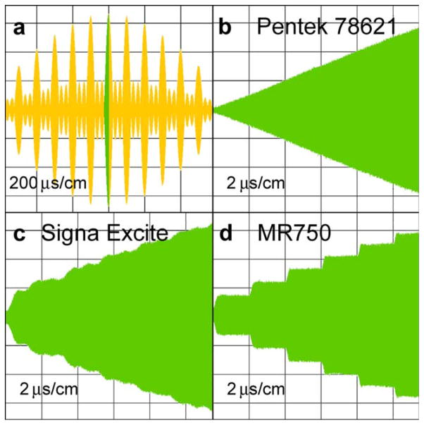
The algorithm used to create tailored pulses produces two digital arrays, one with amplitude data (14 bits) and one with phase (12 bits) data, which are loaded to a transceiver processor and storage exciter in 2-μs increments in the GE Signa EXCITE system. A pulse simulation program showed that even when applying high nonlinearities to the amplitude and phase, distortions as seen in Figure 1a cannot be obtained. However, when phase data were shifted by 3 μs against the amplitude data, the simulator replicated the pattern of Figure 1a. Correction of this behavior requires a shift of digital phase data by 3 μs on hardware with 2-μs update time only. The Fourier transform shift theorem was implemented in the magnetic resonance imaging (MRI) sequence and artifacts were minimized when using a 3-μs shift. The same sequence when played on the MR750 system showed the best result at a 0-μs shift, which leads to the conclusion that although the MR750 is improved, a flaw remains in the system. In spite of the fact that the spectrum is better than the corrected one on the EXCITE system, as seen in Figure 1b, it was still judged to be inadequate.
To improve the spectral quality of RF pulses, a Pentek Waveform Playback PCIe card model 78621 (Upper Saddle River, NJ), which is based on the Texas Instrument DAC5688 chip, was evaluated. This card is controlled by a Virtex-6 FPGA (field-programmable gate array) and is mainly intended to produce radar beams. This card can be synchronized with others of the same type. It has absolute phase accuracy and timing required for varying radar beams without the need for antenna rotation. In the interpolate mode, the D/A converter of this card creates RF pulses with a 2-ns sampling time as well as smooth, stair-step-less modulation of the I and Q channels at a 16-bit resolution. As a result, the spectral quality of an RF pulse created with the same algorithm as pulses in Figure 1a is better as shown in Figure 1c. The same power transmitter and pickup loop were used to acquire RF pulses for all images.
Figure 2 shows several excerpts of RF pulses produced by different modulators and acquired by an Agilent digital oscilloscope DOS6104A. Figure 2a shows the central 1.2-ms region of a 6.4-ms RF pulse. Three other frames: b, c, and d show the short part of the pulse in frame 1 marked by green color. Stair steps of RF modulation are clearly visible for both 3-T Signa EXCITE and MR750 scanners. There are no such steps in the pulse created by the Pentek 78621 card. The spectrum of the pulse created by the DAC5688 chip as seen in Figure 1c has at least two orders of magnitude lower out-of-slice excitations compared with the spectrum of Figure 1a. Ghost slices are not evident. For comparison, the simulation of an ideal stair-step modulation showed harmonics far away from the central spectrum, which do not excite protons inside the imaging object. It is hypothesized that the rounding of steps, as seen in Figure 2d, is the source of the ghost artifacts seen in Figure 1b.
FIG. 2.
Oscillograms of RF pulses obtained by different modulators: (a) the central region of a 6.4-ms long RF pulse at a resolution of 200 μs/cm. The 12-μs segment marked by green is expanded in other windows at a resolution of 2 μs/cm; (b) an envelope created by the Pentek 78621 16-bit digital waveform synthesizer; (c) an envelope created by the GE 3-T Signa EXCITE original modulator; and (d) an envelope created by the GE 3-T MRI750 original modulator.
The unprecedented spectral phase quality and time-course stability of pulses obtained using the DAC5688 chip have another benefit. The 90° RF pulses used in standard two-dimensional MRI methods were programmed to achieve interslice phase coherency that is usually lost because of frequency offsets from the central Larmor frequency. The benefit of this technology becomes more important with increase in the magnetic field of whole-body MRI scanners where phase images of the brain (7,8) carry more information than amplitude images. With phase alignment between all two-dimensional slices, consistent phase analysis in three dimensions can be carried out without the need for additional (and rather long) three-dimensional acquisition. Moreover, in the realm of echo-planar imaging, especially at high resolution, phase contrast in an arbitrary oblique plane can be obtained by postprocessing the full set of phase coherent slices.
Another benefit of the DAC5688 chip was discovered. The phase stability is so high that it is no longer necessary to use a phase reference in the receiver. This was an incidental finding that is not central to the paper. Images with and without a reference were compared.
METHODS
System Design
Two additional computers were used for off-line digital processing. Transmit pulses were formed in the computer that was equipped with the Pentek 78621 card. Pulses were sent to input IN2 of the switching box shown in Figure 3. Input IN1 accepts standard GE pulses sent via switch A to output OUT1, which is connected to the RF power amplifiers. When two positive TTL pulses are sent at the same time to inputs IN3 and IN4, RF input IN1 is disconnected and a pulse from input IN2 is sent to the transmitter. The TTL logic circuit warrants that only when there is a pulse from the scanner programmable DAB8 output TTL line, will the RF pulse from the 78621 card be accepted and for only the duration of the scanner transmitter unblanking pulse. When standard GE sequences are used, which do not excite the DAB8 line by design, all RF pulses are sent to the transmitter just as in the factory configuration. In this work, when an off-line reference signal was needed for comparison with the original scanner configuration, it was created as an extension of the excitation pulse, separated by switch B and sent to the output OUT2.
FIG. 3.
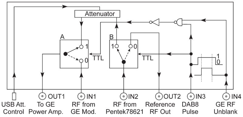
The switching box diagram directing different RF pulses to the RF power transmitter. Output OUT2 is used as a source of the reference signal created by the Pentek 78621 16-bit digital waveform synthesizer.
For every pulse synthesized by the Pentek card, exactly the same pulse was created in the imaging sequence. The original equipment software evaluates the sequence with respect to SAR constraints. In addition to maintain the external pulse in a safe range, the maximum amplitude of the signal arriving at input IN1 was measured and compared with the output level of the 78621 card. They were held the same within an accuracy <1 dB at an output level of 4 dBm, which is the standard for all tested Pentek cards.
The second computer is equipped with 16 bit A/D cards (ECDR-GC316-PMC) made by Mercury for off-line digital acquisition. In contrast to standard methods that create an intermediate frequency, this system acquires the reference signal at the original frequency in parallel with echoes from all receiver coils. The signal mixing is done by software as described in Ref. (9) and shown in Figure 4. The 100-MHz acquisition clock is derived from the 10-MHz reference clock of the scanner in a phase-locked loop. This clock signal is also sent to the Pentek 78621 card to synchronize an internal 500-MHz clock used by the DAC5688 chip. With a single RF unblanking pulse sent to the card, full synchronization of the scanner and the off-line transmitter system was achieved.
FIG. 4.

Configuration of the off-line acquisition system.
Excitation Using Tailored Pulses
Tailored pulses were formed by the inverse Fourier transform of the required slice profiles, including not only positions computed against the Larmor frequency but also relative phases (10). The pulse data in the form of I and Q 16-bit arrays were multiplied by a Hamming window to reduce truncation artifacts. The pulse duration time was 6.4 ms with a final 2-ns update time. This pulse duration is twice that of the default mode of the normal GE scanner, which reduces the peak power required for multiband excitation so that a 4-fold acceleration can be achieved at a 90° flip angle. In practice, however, an Ernst angle was used. Each complex-valued composite RF pulse was formed from a single transmit frequency. With this method, reference slices needed for multislice separation can be acquired with exactly the same phase as the combined image by masking the unneeded part of the composite profile. For four slices, a 30° phase difference between each slice is a reasonable choice.
The Larmor frequency was created by an on-chip numerically controlled oscillator shown in Figure 5. The complex modulated waveforms were stored in the internal 512 MB memory of the 78621 card, which permits fast transfer of data to the input of the DAC5688 chip without engaging the main computer central processing unit. The modulating signal upsampling rate, described below, was chosen to obtain the frequency deviation range up to ±3.9 MHz. This rate was chosen to compare with standard imaging methods of the GE scanner where a reference waveform, shifted by 2.25 MHz, is used for mixing with the MRI analog signal before A/D conversion. In these comparisons, an off-line reference signal was created as an extension of the excitation pulse and was separated in the switching box. The modulating I and Q channels were created by harmonic functions with continuously increasing argument. Tests showed that a phase argument of cosine and sine as large as 1019 radians can still produce accurate waveforms. With a 2-ns update time, the phase will be good for more than 500 years.
FIG. 5.
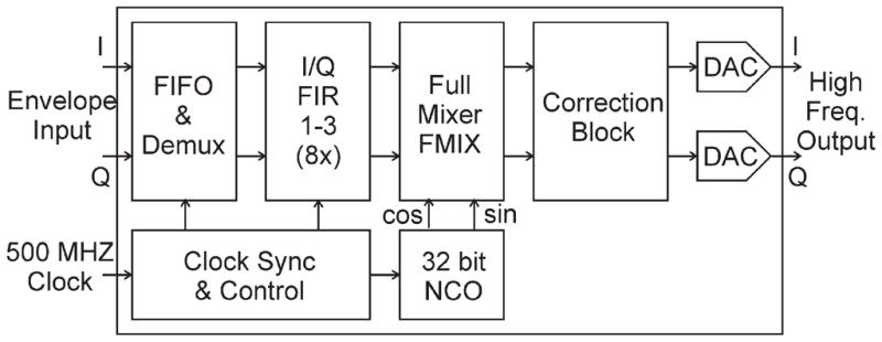
The RF track of the DAC5688 chip. The figure is an excerpt from the Texas Instruments manual for 16-bit, dual-channel, interpolating digital-to-analog converter DAC5688.
All pulses were created with 128-ns steps and were synchronously upsampled in two stages. The 8-fold upsampling is carried out by the Virtex-6 FPGA interpolator and then sent to the DAC5688 chip for another 8-fold upsampling in I/Q FIR block as seen in Figure 5. This process of digital convolution is equivalent to making a Fourier transform of the pulse, filling zeroes on the left and right parts of the spectrum thus increasing frequency range by 64 times, and making an inverse Fourier transform. The final modulation, at 500 MHz, was made by a Full Mixer (FMIX), a part of the DAC5688 chip.
The pulse quality was tested on two scanners: 3-T GE Signa EXCITE and 3-T GE MR750. On the 3-T GE MR750 scanner, spectra of RF pulses excited by internal modulator were tested with a pickup loop for comparison. The spectra are shown in Figure 1. The following pulse parameters were used: single-slice bandwidth of 1250 Hz, simultaneous excitation of four slices at 30 slice thickness separation, and pulse duration of 6.4 ms. As shown in Figure 2, the slice separation was reduced to a thickness of eight slices to increase the time of the ramp-type part of the pulse for better visualization of a stair-step modulation effect at a 2 μs/cm resolution.
The phase coherence of excited slices on the 3-T GE Signa EXCITE was tested using a standard GE sequence. In this sequence, the 90° 3.2-ms pulse at a 2.5-kHz bandwidth was replaced with a synthesized pulse of the same shape and duration created using 128-μs steps and was interpolated 64 times. When used, the reference signal for MRI detection was separated in the box shown in Figure 3 and sent to channel 0 as shown in Figure 4. The phase computation of a modulation signal started from the rising edge of the transmitter unblanking pulse. At the same moment, the numerically controlled oscillator accumulator of the DAC5688 chip was reset thereby achieving full coherence of RF pulses with the MRI sequence itself. Because of the low bandwidth of the gradient amplifier, all scanner pulses were delayed accordingly to play RF pulses in the center of slice selection gradients. This delay was not sufficiently precise and had to be adjusted.
Acquisition
All acquisitions were done off-line using a computer equipped with Mercury ECDR-GC316 A/D cards running on the Linux operating system and driven by the GE Signa EXCITE 3-T MRI scanner. In principle, the digital pulse generator described here could be used with any scanner, but detailed knowledge of the acquisition system would be required to reset the intershot phase.
A two-dimensional phantom study with an aim to achieve interslice phase coherency was carried out using a gradient-encoding sequence with the following parameters: bandwidth (BW) = 31.25 kHz; 256 × 256 resolution; number of excitation (NEX) = 1; field of view (FOV) = 24 cm; slice = 3 mm; 31 interleaved slices; repetition time (TR) = 1 s; and echo time (TE) = 7.1 ms. A single-channel quadrature head coil was used for the acquisition.
A gradient-recalled EPI human study was carried out under a protocol approved by the Medical College of Wisconsin’s Institutional Review Board. The sequence of our own design was used (11) for off-line acquisition by the 32-channel custom system made by ClearMRI Solution (Toronto, ON, Canada). The parameters of the EPI sequence used for multiband acquisition were as follows: BW = 125 kHz; 64 × 64 resolution; FOV = 24 cm; slice = 1 mm; four axial multiband slices; 20 mm separation; four slices after separation; TE = 28.7 ms; and TR = 2 s. Ten image time courses were acquired as reference slices. Time courses of 20 images of resting-state data were acquired in the multiband mode. Each RF pulse was followed by a reference signal offset of 2.25 MHz and was acquired in a separate channel. For fat suppression, the original GE Signa EXCITE pulses were used because lack of coherence did not affect imaging. The DAB8 pulses sent to the switching box shown in Figure 3 were used for 90° RF excitations only. A 32- channel RF coil made by Nova Medical (Wilmington, MA) was used for imaging. The coil has four elements in the Z-direction. The eight radial elements can provide further acceleration using a sensitivity encoding (SENSE)-type method. The separation of 4-fold acceleration of axial slices was done using four complex independent equations, the theoretical maximum, and amplitude images were derived for display.
RESULTS
Phantom Study
The stability and coherence of pulses were tested. For this purpose, a GE sequence was used at a 256 × 256 resolution. In this method, each ky-space line is acquired separately and is repeated 256 times with varying phase-encoding gradient. Phase coherence of all ky-space lines is required to obtain an undistorted image that is created by Fourier transformation. Any phase deviation, even of a single ky-space line, creates smearing in the image in the phase-encoding direction covering areas below and above the center of the imaging object. Until now, this coherency was obtained by mixing a reference with MRI signals before acquisition. Because the same low frequency digital synthesizer and up-converting free-running clock are used to obtain a 90° pulse and the reference signal, coherency between them is assured. This procedure was sufficient to obtain consistent k-space coverage in spite of the lack of coherency between RF pulses and the MRI sequence itself. In tests of our new approach to transmit- pulse formation, we conducted mixing in software after digitizing the reference and MRI signals as shown in Figure 4. This permitted comparison of images formed with and without a reference signal by a button press. There were no visibly apparent differences between images. In this comparison, a 20-μs dither of the TR value, which is used in the GE product, was disabled.
A test of interslice phase variation was performed. The same gradient-recalled echo sequence was used to create 31 interleaved axial slices, with the scanner in its factory configuration. A single coronal image of the phase was created from the set of axial phase images and is shown in Figure 6a. The lack of phase coherency is evident. Figure 6c shows an example of a single-phase axial slice.
FIG. 6.
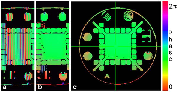
Phase images obtained by a conventional gradient-echo method at a resolution of 256 × 256: (a) coronal image created from the set of 31 axial slices using the GE 3-T Signa EXCITE original modulator showing no phase coherency; (b) coronal image created from the set of 31 axial slices using the Pentek 78621 16-bit digital waveform synthesizer. Interslice coherence is evident; (c) example of a single axial phase image used to construct the coronal cross sections in (a) and (b).
The Pentek modulator was then tested. Initially, a reference signal was used to create interslice coherency. The phase of the reference signal was changed for every slice to compensate for the slice frequency offsets. Because the same Larmor frequency was used to create all slice pulses, the pulse position was adjusted precisely in order to rephrase properly the magnetization across each slice that is caused by the refocusing gradient. A small error in positioning can be neglected for the central slice. This error will change the amplitude of magnetization slightly but will not affect the phase because of the spectral symmetry. For the off-resonance slices, the refocusing effect will be the same but the phase of excitation will vary proportionally to the frequency deviation. An appropriate adjustment of the RF pulse position was done in the prescan mode by consecutively playing two adjacent slices and comparing the phase of echoes. The final adjustment was carried out in similar fashion but with slices of larger separation. An accuracy of adjustment of 1 μs was sufficient to obtain the result seen in Figure 6b.
The same test as in the previous paragraph was conducted without using a reference signal. In this case, the phases of excited slices were corrected in a similar manner but without explicit use of a reference signal. The results were unchanged, as expected. The same slice-phase correction method was also tested for the EPI sequence and it worked well.
Human Study
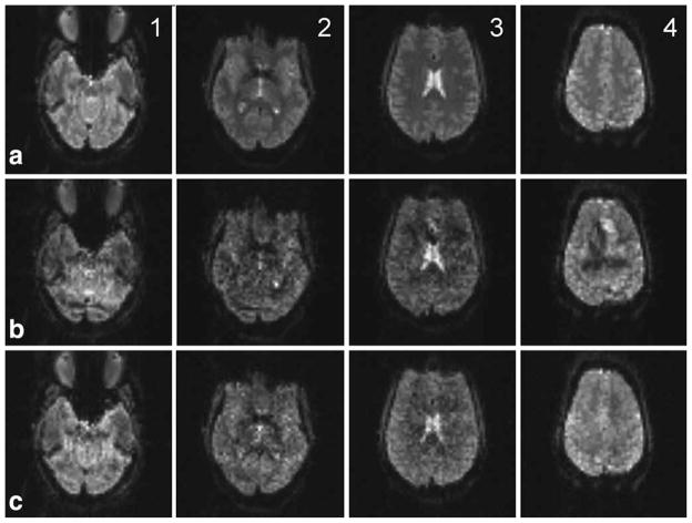
On an initial midbrain sagittal image, six 1-mm axial slices separated by 20 mm were prescribed. The central four slices were used for multiband acquisition. The goal was to have the ghost slices appear inside the brain with the most superior slice smaller than the other slices as seen in Figure 7 (b4). For slice separation, an algorithm described in (2) was used but with a double pass of B0, Gx, and Gy corrections required for a longer time-course series of images with a high duty cycle of applied gradients. This modification was needed because the magnetic field drift across the series was high and final images not only had a drift of phase in relation to reference images but also were shifted by a few pixels in the phase-encoding direction, about one pixel per 25 Hz of the Larmor frequency change. The quality of separated slices created using the GE 3-T Signa EXCITE original modulator (row b in Fig. 7) is lower than obtained using the DAC5688 chip (row c). The shape outline of the most superior ghost is visible in image (b4).
FIG. 7.
Four slices, 1-mm thick, spaced by 20 mm, were placed to allow for incidental excitation of two ghost slices in the lower and upper parts of the brain. Row (a) shows four reference slices 1–4. Row (b) shows separated slices that were excited using the GE 3-T Signa EXCITE original modulator. Row (c) shows separated slices that were excited using the Pentek 78621 16-bit digital waveform synthesizer. On the separated image (b4), there is an explicitly visible interference pattern of the size and shape of the first top ghost slice that was created using the GE 3-T Signa EXCITE modulator. The Pentek synthesizer does not create ghosts and therefore the equivalent slice (c4) is clean and resembles the reference slice (a4).
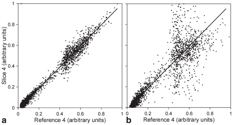
To compare results, scatter plots of corresponding pixels of slice 4 of the first image in the series and the equivalent reference slice are shown in Figure 8. In an ideal case, all points of the graph should lie on a diagonal axis. When the Pentek modulator was used, graph (a) of the unaliased image (c4 in Fig. 7) shows good agreement with the corresponding reference slice. In contrast, graph (b) shows great discrepancy of the unaliased slice (b4 in Fig. 7) with its reference slice. The main spread between values in the range of 40–70% comes from the interference of the unaliased image with the exited superior ghost slice.
FIG. 8.
Scatter plots of corresponding voxel signal intensities of the separated slice 4 of the first image of the EPI series and the equivalent reference slice. Graphs: (a) plot for the slice created by the Pentek 78621 16-bit digital waveform synthesizer and (b) plot for the slice created by the GE 3-T Signa EXCITE modulator.
DISCUSSION
High spectral quality and stability of RF pulses was possible by the use of the Texas Instrument D/A converter DAC5688 in the final stage of RF signal processing at a clock rate of 500 MHz. Short connections within the chip, which are much less than the wavelength at this frequency, eliminated errors related to signal delays and phase changes. The use of the chip internal interpolator (I/Q FIR in Fig. 5) at a maximum up-conversion rate reduced the input data clock down to 62.5 MHz, well below the limit of the Virtex-6 FPGA that controls the modulator. A new D/A converter, DAC3484, has been released by Texas Instrument and is being implemented. The output frequency at 1.25 GHz clock speed is increased to 500 MHz. Extension of the methods of this paper to the new card is now in the process of evaluation.
The interslice coherence, which is set by adjusting the position of the RF pulse in relation to the slice selection gradient, is robust and valid not only for volumetric phase contrast imaging but also for other sequences. The phase difference between slices in multiband excitation depends on this coherence as well. After initial positioning of the RF pulse, further adjustment is not necessary.
CONCLUSION
Synthesizers with limited modulation-time steps should be replaced not only because of the improved spectral quality of RF pulses but also for the exceptional phase control of these pulses at different slice-selection frequencies.
The primary goal of this work was to solve a previously unidentified problem in multiband excitation profiles, namely, the occurrence of so-called ghost slices. In the course of the work, we arrived at a solution to the problem that has far-reaching implications in design of magnetic resonance instruments. The key is the use of a system clock for pulse formation that is at the Larmor frequency. As a consequence, all RF pulses can be said to be “phase coherent.” It follows that phase reference signals are no longer required in detection. It also follows that complex-valued functional connectivity studies across the full brain at high resolution are possible. Recent technology development, apparently motivated by radar advances, allows the output frequency to be as high as 600 MHz when using an upgraded DAC34SH84 converter running at 1.5 GHz clock. This clock speed is sufficient for MRI applications at magnetic fields up to 14 T.
Acknowledgments
Grant sponsor: National Institutes of Health; National Institute Of Biomedical Imaging And Bioengineering; Grant number: R01 EB007827.
The authors thank Rodger Hosking from Pentek, Inc for advice in writing a device driver for their PCIe 78621 card.
References
- 1.Jesmanowicz A, Li S-J, Hyde JS. Multi-slice two- and four-fold acceleration with single- and eight-channel coils, respectively [abstract]. Proceedings of the 17th Annual Meeting of ISMRM; Honolulu, Hawaii, USA. 2009. p. 1089. [Google Scholar]
- 2.Jesmanowicz A, Nencka AS, Li S-J, Hyde JS. Two-axis acceleration of functional connectivity magnetic resonance imaging by parallel excitation of phase-tagged slices and half k-space acceleration. Brain Connect. 2011;1:81–90. doi: 10.1089/brain.2011.0004. [DOI] [PMC free article] [PubMed] [Google Scholar]
- 3.Moeller S, Yacoub E, Olman CA, Auerbach E, Strupp J, Harel N, Ugurbil K. Multiband multislice GE-EPI at 7 Tesla, with 16-fold acceleration using partial parallel imaging with application to high spatial and temporal whole-brain fMRI. Magn Reson Med. 2010;63:1144–1153. doi: 10.1002/mrm.22361. [DOI] [PMC free article] [PubMed] [Google Scholar]
- 4.Feinberg DA, Moeller S, Smith SM, Auerbach E, Ramanna S, Glasser MF, Miller KL, Ugurbil K, Yacoub E. Multiplexed echo planar imaging for sub-second whole brain fMRI and fast diffusion imaging. PLoS One. 2010;5:e15710. doi: 10.1371/journal.pone.0015710. [DOI] [PMC free article] [PubMed] [Google Scholar]
- 5.Larkman DJ, Hajnal JV, Herlihy AH, Coutts GA, Young IR, Ehnholm G. Use of multicoil arrays for separation of signal from multiple slices simultaneously excited. J Magn Reson Imaging. 2001;13:313–317. doi: 10.1002/1522-2586(200102)13:2<313::aid-jmri1045>3.0.co;2-w. [DOI] [PubMed] [Google Scholar]
- 6.Bernstein MA, King KF, Zhou XJ. Handbook of MRI pulse sequences. Oxford: Elsevier Academic Press; 2004. [Google Scholar]
- 7.Christoforidis GA, Bourekas EC, Baujan M, Abduljalil AM, Kangarlu A, Spigos DG, Chakeres DW, Robitaille P-ML. High resolution MRI of deep brain vascular anatomy at 8 Tesla: susceptibility-based enhancement of the venous structure. J Comput Assist Tomogr. 1999;23:857– 866. doi: 10.1097/00004728-199911000-00008. [DOI] [PubMed] [Google Scholar]
- 8.Duyn HJ. Study of brain anatomy with high field MRI: recent progress. Magn Reson Imaging. 2012;28:1210–1215. doi: 10.1016/j.mri.2010.02.007. [DOI] [PMC free article] [PubMed] [Google Scholar]
- 9.Jesmanowicz A, Hyde JS. Direct MRI detection at 3T using an FPGA-controlled high-speed digital receiver [abstract]. Proceedings of the 14th Annual Meeting of ISMRM; Seattle, Washington, USA. 2006. p. 2027. [Google Scholar]
- 10.Jesmanowicz A, Hyde JS. Perfusion imaging using velocity encoding [abstract]. Proceedings of the 11th Annual Meeting of ISMRM; Toronto, Canada. 2003. p. 156. [Google Scholar]
- 11.Jesmanowicz A, Bandettini PA, Hyde JS. Single-shot half k-space high-resolution gradient-recalled EPI for fMRI at 3 Tesla. Magn Reson Med. 1998;40:754–762. doi: 10.1002/mrm.1910400517. [DOI] [PubMed] [Google Scholar]


