Numerical modeling indicates that hierarchical clustering of ryanodine receptors in cells of the sinoatrial node is crucial to the calcium clock and thereby to regulation of heart rate.
Abstract
The sinoatrial node, whose cells (sinoatrial node cells [SANCs]) generate rhythmic action potentials, is the primary pacemaker of the heart. During diastole, calcium released from the sarcoplasmic reticulum (SR) via ryanodine receptors (RyRs) interacts with membrane currents to control the rate of the heartbeat. This “calcium clock” takes the form of stochastic, partially periodic, localized calcium release (LCR) events that propagate, wave-like, for limited distances. The detailed mechanisms controlling the calcium clock are not understood. We constructed a computational model of SANCs, including three-dimensional diffusion and buffering of calcium in the cytosol and SR; explicit, stochastic gating of individual RyRs and L-type calcium channels; and a full complement of voltage- and calcium-dependent membrane currents. We did not include an anatomical submembrane space or inactivation of RyRs, the two heuristic components that have been used in prior models but are not observed experimentally. When RyRs were distributed in discrete clusters separated by >1 µm, only isolated sparks were produced in this model and LCR events did not form. However, immunofluorescent staining of SANCs for RyR revealed the presence of bridging RyR groups between large clusters, forming an irregular network. Incorporation of this architecture into the model led to the generation of propagating LCR events. Partial periodicity emerged from the interaction of LCR events, as observed experimentally. This calcium clock becomes entrained with membrane currents to accelerate the beating rate, which therefore was controlled by the activity of the SERCA pump, RyR sensitivity, and L-type current amplitude, all of which are targets of β-adrenergic–mediated phosphorylation. Unexpectedly, simulations revealed the existence of a pathological mode at high RyR sensitivity to calcium, in which the calcium clock loses synchronization with the membrane, resulting in a paradoxical decrease in beating rate in response to β-adrenergic stimulation. The model indicates that the hierarchical clustering of surface RyRs in SANCs may be a crucial adaptive mechanism. Pathological desynchronization of the clocks may explain sinus node dysfunction in heart failure and RyR mutations.
INTRODUCTION
Under normal circumstances, the rhythm of the heart beat is generated in the sinoatrial node. Single sinoatrial node cells (SANCs) generate spontaneous, repetitive action potentials as a result of a gradual diastolic depolarization (DD) of the cell membrane bringing it to threshold for a rapid, regenerative depolarization driven largely by the L-type calcium current.
How the DD is generated has been a matter of study for decades. DiFrancesco and Noble (2012) demonstrated the existence of a “funny” inward current If, activated gradually by hyperpolarization. However, in the past decade, much evidence has accumulated (Lakatta et al., 2010) showing the occurrence of local calcium release (LCR) events from the SR in diastole. These LCR events couple to the electrogenic sodium–calcium exchanger (NCX), generating an inward current that accelerates the DD. In this way, LCR events, apparently generated by RyRs, make a major contribution to the maintenance and control of heart rate. This has led to the coupled clock theory of SANC automaticity (Maltsev and Lakatta, 2009). The membrane clock is the system of sarcolemmal currents, which are capable of generating periodic action potentials. The calcium clock consists of the machinery of calcium cycling by the SR-RyRs, sarco/endoplasmic reticulum Ca2+-ATPase (SERCA)-2 calcium pump, calsequestrin (CaSQ), etc., which is capable, on its own, of generating LCR events, which are stochastic, partially periodic, and locally propagated. The two clocks are coupled by the NCX current, which causes them to become mutually entrained at a single beating rate (Lakatta et al., 2010).
In ventricular myocytes, RyRs can generate spontaneous, localized calcium sparks and, under conditions of high calcium loading, global calcium waves, which are believed to be regenerative CICR propagating by calcium diffusion (Fabiato, 1983; Stern et al., 1983). LCR events in SANCs resemble calcium waves, but they propagate only locally and occur in multiple locations in the cell during each cardiac cycle. The mechanisms that account for their distinctive morphological features have not been well determined.
Maltsev and Lakatta (2009) modeled the coupled clock system by a system of ordinary differential equations that include, in addition to the usual membrane currents, a single cytosolic space containing calcium and buffers, a submembrane space (subspace), and an SR compartment. This common pool model has been remarkably effective in explaining the role of the SR in regulating beating rate.
The Maltsev–Lakatta model, however, does not take explicit account of the stochastic nature or propagation of LCR events. More recently, Maltsev et al. (2011) constructed a model in which a 2-D grid of discrete “calcium release units” (CRUs) communicate by calcium diffusion within a subspace. When this model is coupled to a system of SANC sarcolemmal currents (Maltsev et al., 2013), it acts as a calcium clock, synchronizing with the action potentials.
These models have important limitations. The common pool models represent the calcium release process by an ensemble-average open probability of RyRs. Moreover, the model relies on RyR inactivation to terminate release. However, in recent years, no sufficiently strong inactivation process has been identified, and the present consensus is that RyR closure (i.e., spark termination) is primarily mediated by local SR lumenal depletion (Lukyanenko et al., 1998; Terentyev et al., 2002). The CRU models have spatial resolution but lump the properties of (clusters of) RyRs into stochastic “black box” devices whose kinetics are chosen to match experimental measurements of the LCRs.
All of these models incorporate a subspace in which calcium is locally confined beneath the sarcolemma. There is no known anatomical basis for such confinement except in areas where the SR forms dyad junctions with the sarcolemma. As a heuristic device the subspace works, but it fundamentally misrepresents the situation because it implies that calcium released anywhere under the sarcolemma can be sensed immediately anywhere else on the cell surface.
The biophysical mechanisms behind the “calcium clock” remain uncertain. Using immunofluorescent staining, here we demonstrate that, on the surface of rabbit SANCs, RyRs are located in irregularly spaced and sized clusters forming a network in which short intercluster distances are represented. Based on this data, we have constructed and explored the first model that represents SANC dynamics in terms of 3-D local calcium dynamics and the stochastic gating of individual channels (with RyR having no inactivation). The model generates locally propagated LCR events, with the emerging Ca2+ clock contributing to spontaneous action potential firing via activation of the NCX, allowing beating rate to be regulated by the calcium cycling system. This model shows that the observed role of diastolic calcium release in rate regulation can be explained by known biophysical processes but depends on particular features of the RyR distribution in SANCs.
MATERIALS AND METHODS
Our model is an extension of an excitation–contraction model described previously (Stern et al., 1997, 1999, 2013).
Generic model
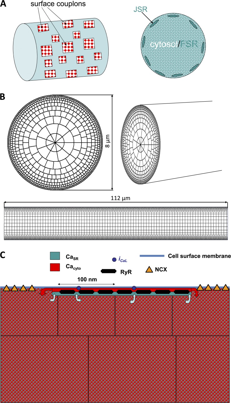
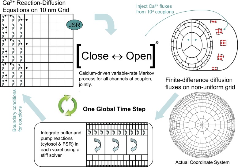
The generic structure of the model consists of three components: (1) Sarcolemmal membrane currents and voltage are represented by ordinary differential equations, as in other cellular electrophysiology models, except for the L-type calcium current, which is handled separately and stochastically. (2) Diffusion and buffering of calcium in the cytosol, and in the free SR (FSR), are represented by (discretized) partial differential reaction–diffusion equations. The FSR is treated as a fine random network, considered as a separate, continuous space coextensive with the cytosol but having a small fractional volume as measured ultrastructurally. (3) Couplons, which are CRUs consisting of dense clusters of RyRs colocalized with L-type calcium channels at 15-nm dyad junctions between the junctional SR (JSR) and the sarcolemma (Fig. 1, A and C). Each couplon has one JSR compartment containing CaSQ. The JSR receives calcium from the adjacent FSR through a diffusion resistance representing the several fine, tubular nexi observed ultrastructurally (Brochet et al., 2005). Calcium from the JSR is released into the dyadic space through open RyRs at a rate proportional to the free calcium gradient between the JSR and the dyadic space at the location of each RyR. The dyadic space of each couplon is discretized into a 2-D grid of 10-nm squares on which local calcium and diffusible buffer evolve according to reaction–diffusion equations, which are integrated along with the calcium concentration in the JSR compartment. RyRs are located at 30-nm spacing, and L-type channels are randomly placed. Calcium diffuses from the edges of the cleft into the adjacent cytosol. Joint gating of RyRs and L-type channels is simulated by a custom-modified Gillespie Monte Carlo algorithm that generates an exact realization of the high dimensional variable-rate Markov process controlled by voltage and instantaneous local calcium (Stern et al., 1997).
Figure 1.
Schematic diagram of the geometry of the model. (A) A schematic diagram of a section of the cylindrical cell, showing subsurface JSR and couplons, with the interior consisting of cytosolic and FSR spaces. (B) The nonuniform coordinate grid defining the voxels used in the simulations. (C) Relationship of surface couplon and voxels. Each couplon consists of a square array of RyRs and a single JSR terminal compartment. Each voxel has cytosolic and FSR components. Calcium released to the cleft diffuses from the edges of the cleft to the cytosolic component of the neighboring voxels. The JSR refills from the FSR component of containing voxels.
Further details of the model and the computational methods used to integrate the model are described in the Appendix.
Specific rabbit SANC model
The above generic model structure can be used to represent excitation–contraction coupling in any cardiac myocyte. For this study, we specialized the model to rabbit SANCs:
Geometry.
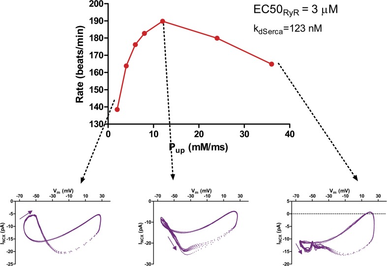
The cell is represented as a cylinder of radius 4 µm and length ∼100 µm (Fig. 1, A and B). To avoid edge effects, periodic boundary conditions were applied at the longitudinal ends, making the domain into a toroid. In principle, this could permit the existence of nonphysiological reentrant calcium waves traveling around the long axis, but this was never observed for conditions actually simulated. Because SANCs do not have t-tubules, all couplons are surface junctions between the JSR and the sarcolemma at r = 4 µm. For the present study, we simulated only cells that have no nonjunctional RyRs in the interior of the cell, which constitute about half of isolated SANCs (see below). This was done to minimize the computational burden. Of note, there is evidence that these “hollow” cells are found in the center area of the sinoatrial node where the primary pacemaking takes place (see Fig. 6 E in Musa et al., 2002).
Figure 6.
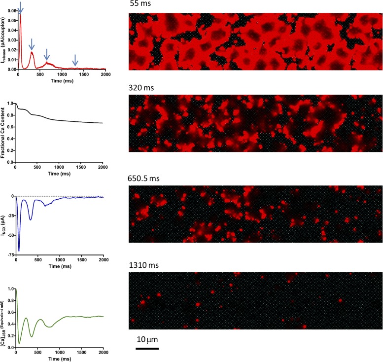
Calcium chaos produced by the same conditions as in Fig. 5, except with initial calcium load increased to 1.2 mM.
Coordinate system.
Because of the lack of interior RyRs, calcium gradients are expected to become shallower as one penetrates into the interior of the cell, away from discrete sources. This allows the use of a nonuniform coordinate grid, with larger voxels toward the center (Fig. 1 B) greatly decreasing the computational burden. At the cell surface, voxels are ∼100 nm in each direction. No anatomical subspace is present.
Reaction–diffusion equations.
For comparability, the system of cytosolic buffers was taken to be the same as in the common pool Maltsev–Lakatta model (Maltsev and Lakatta, 2009). There are seven dynamical variables at each voxel: [Ca2+]cyto, [Ca-fluo], [Ca-calmodulin], [Ca-troponin-calcium-site], [Ca-troponin-Mg-site], [Mg-troponin], and [Ca2+]FSR. Buffer reactions are dynamic, with on-rates and off-rates given in the Supplement 1, except for CaSQ, which is treated as a fast equilibrium buffer. SERCA-2 pump flux is computed according to the model of Shannon et al. (2004) rather than that used in Maltsev–Lakatta, taking account of bidirectional fluxes in keeping with thermodynamics. Pump flux is transported between the cytosolic and FSR compartments of the voxel, taking account of the relative fractional volumes of the two compartments. The FSR is assumed to be uniformly distributed throughout the cell, based on the distribution of SERCA-2 in immunofluorescent stains (see Appendix). Flux of the NCX exchanger is computed according to the formulation in Maltsev–Lakatta and applied to the free calcium of the outermost layer of voxels. Sodium and magnesium concentrations are taken to be constant. Detailed equations are given in Supplement 1.
Sarcolemmal currents.
Membrane currents follow the same formulations as in Maltsev–Lakatta, which are in turn derived from Kurata et al. (2002), with the exception of the L-type calcium current. Because L-type channels couple directly to RyRs via nanoscale calcium gradients, the L-type channels must be explicitly represented in the stochastic formulation of the couplons. The cardiac L-type channel has a complicated gating scheme involving inactivation by voltage and by local calcium binding to channel-tethered calmodulin (Tadross et al., 2008). However, for the purpose of comparability with previous SANC models, we constructed an L-type gating scheme from the Hodgkin–Huxley-style currents in the Kurata model by assuming that the gating variables in that model are, in fact, open probabilities of sequential binary gates. As described in the Appendix, this gives an eight-state Markov process whose ensemble average properties exactly recapitulate the dynamics of the Hodgkin–Huxley gating variables. It was necessary to markedly decrease the closing rate constant of the calcium inactivation gate to account for the much larger local calcium gradients in the dyadic cleft compared with the average values in the subspace of the Kurata model. The NCX current is calculated locally at each surface voxel and summed over the surface to calculate its contribution to membrane voltage dynamics. Full equations are in the Appendix.
Couplons.
Couplons are square nxn arrays of RyRs whose locations and sizes are discussed in Results. The relationship of couplons, JSR, and near-surface voxels containing cytosolic and FSR compartments is shown in Fig. 1 C. RyRs gate according to a simple two-state scheme as in Stern et al. (2013), with opening rate proportional to a power (generally 2) of local cleft free calcium, with a rate coefficient that varies linearly with local JSR free calcium. The JSR volume of each couplon is taken to be proportional to its number of RyRs. There is no inactivation, so termination of couplon activity depends entirely on local depletion of JSR calcium.
Detailed methods, including cell isolation, immunoblotting, and immunofluorescence staining, as well as computational techniques, are described in the Appendix.
Online supplemental material
Fig. S1 gives full-resolution 2-D confocal images of 25 cells studied. The online supplemental material also contains nine movies of simulated Ca2+ dynamics. Supplement 1 gives detailed equations of the model, and Supplement 2 is a series of PowerPoint slides that display the details of the statistical analysis of tangential sections of six SANCs with immunofluorescent staining for RyR2. The online supplemental material is available at http://www.jgp.org/cgi/content/full/jgp.201311123/DC1.
RESULTS
Propagation of LCR events fails at sarcomere spacing of couplons
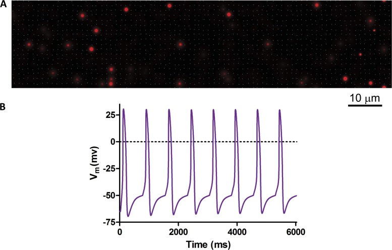
We initially placed couplons on the cell surface in a regular grid at 1.4-µm spacing, as was done in the 2-D CRU model (Maltsev et al., 2011). Using 7 × 7 couplons (49 RyRs, 210-nm couplon width) and RyR gating rate constants consistent with measurements in lipid bilayer (Guo et al., 2012) produced only isolated sparks (Fig. 2 A). Propagated LCR events did not form. Under free-running conditions, action potentials were generated by the membrane clock at a slow rate that was essentially unaffected by SR calcium cycling (Fig. 2 B).
Figure 2.
The model prediction when couplons were placed at 1.4-µm spacing. (A) Isolated calcium sparks were generated, with no significant propagation. (B) Action potentials produced by the model in A. Beating rate was slow, with no terminal DD as a result of spontaneous calcium release.
In the CRU model, CRU calcium sensitivity and refractory period could be chosen by fiat. In the present model, these are properties of couplons, determined by the dynamics of individual RyRs. If RyR sensitivity and/or couplon size is increased, effective CRU sensitivity is increased. However, in the absence of RyR inactivation, this is limited by the development of metastable sparks (Stern et al., 2013) in which CICR at a couplon “latches up” so that release does not terminate. When RyR sensitivity or couplon size was increased in an attempt to produce propagated LCR events, such a metastable state supervened, in which sparks failed to terminate and all couplons remained permanently active resulting in JSR depletion and continuous local calcium cycling around the individual couplon (not depicted).
The problem is evidently that, in the absence of a confining subspace, calcium released from a cell surface couplon can diffuse in three dimensions and be captured by cytosolic buffers before it can trigger release by an adjacent couplon. To quantify this problem, we performed a deterministic simulation of the single-step propagation event. In this simulation, calcium is released from surface-located JSR store through a fixed number of open RyRs, and is allowed to diffuse and react with cytosolic buffers in a half-space. We then calculate the cumulative probability that any RyR in a couplon located on the surface at a distance w opens, and take this as a conservative estimate of the probability that fire–diffuse–fire propagation will occur.
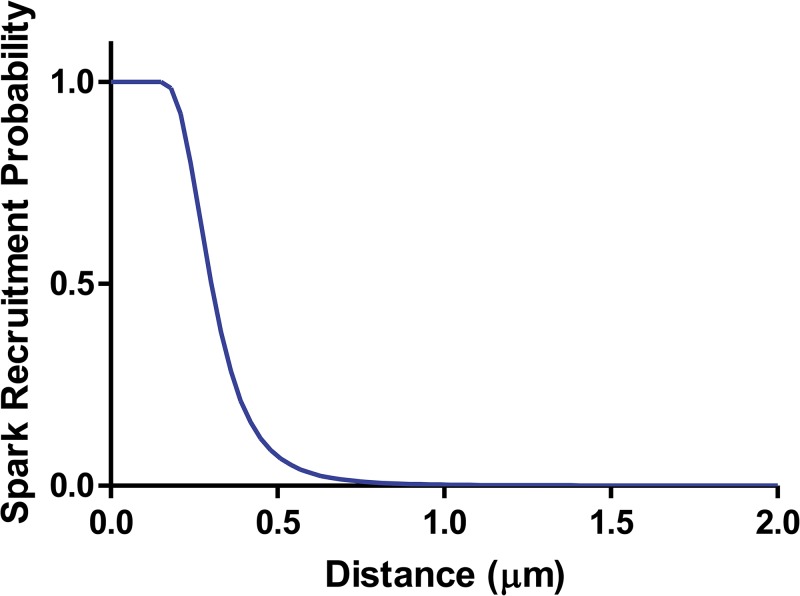
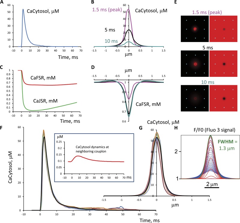
Propagation probability is plotted in Fig. 3 as a function of the couplon spacing w. It can be seen that propagation fails for spacing greater than ∼0.7 µm. Although the exact numbers can be modified by changing the assumed RyR sensitivity and cooperativity, JSR volume, etc., the probability falls off so rapidly that it would not be practical to achieve propagation at distances approaching sarcomere length in this geometry. This problem can be understood by a qualitative argument. Calcium distribution in a spark is shown in Fig. 4. At a distance of 1.4 µm, cytosolic calcium is still elevated enough to be clearly visible with sensitive fluorescent dyes (Fig. 4 H), but it is only modestly above background. To maintain propagation, this would have to have a substantial probability of triggering a neighboring spark within ∼10 ms. But if RyR sensitivity were high enough to achieve this, then resting calcium would generate an extremely high rate of spontaneous sparks (unless RyR activation had extremely high cooperativity). Notice that the sparks in Fig. 4, although they do not reach neighboring couplons, already show prolonged and variable tails (F), indicating that they are on the verge of metastability.
Figure 3.
Sparks can’t jump far. The probability that calcium from a spark (20 RyRs opened, release flux limited by local JSR depletion) would trigger a spark at a neighboring couplon, as a function of couplon-to-couplon distance, from a deterministic diffusion model. Variation of parameters did not change the basic conclusion that recruitment at a distance of 1.4 µm is essentially impossible.
Figure 4.
Dynamics of cytosolic, JSR, and FSR calcium of an isolated spark as in Fig. 2. (A) Cytosolic calcium as a function of time at the spark center. (B) Spatial profile of cytosolic calcium at three time points. (C) Time course of JSR calcium and FSR calcium at the center. (D) Spatial profile of the FSR blink. (E) Images of cytosolic and FSR calcium at three time points. (F and G) Overlay of multiple spark time and space profiles. (Inset) Time course of cytosolic calcium at a neighboring couplon 1.4 µm away. (H) The simulated fluorescence profile of the spark using 100 µM fluo-3 as it evolves in time (each millisecond): red, before peak (rise phase); green, at the peak; blue, after the peak (decay phase). At the peak of fluorescence it has a full width at half-maximum of 1.3 µm, comparable to other spark simulations (e.g., Smith et al., 1998). The spark has a high peak cytosolic [Ca2+] of tens of micromolar, but this decays rapidly with distance, so that at neighboring couplons it is insufficient to trigger another spark with high probability, although sufficiently above background to be visible with sensitive fluorescent dyes. The JSR “blink” has a deep nadir, and then recovers slowly, as found in previous simulations (Sobie et al., 2002; Ramay et al., 2011; Laver et al., 2013; Stern et al., 2013). FSR calcium near the center of the spark shows a shallower blink, but in the periphery there is an overshoot caused by uptake by SERCA of cytosolic calcium diffusing from the spark. An overlay of multiple sparks shows the presence of a long stochastic tail of release consistent with the fact that these sparks are on the border of metastability.
The above analysis is compatible with a model-independent statistical study by Izu et al. (2007), who found that sparks in ventricular cells increase the probability of a spark in a neighbor substantially (10–20-fold above resting rate) where neighbors were available within 0.5–1 µm along the z-line. However, because resting spark rate is so low, even that large influence gave only a 2% chance of a spark jumping, and the influence at 2 µm was nil.
Waves and chaos with regular couplon arrays
As suggested by the analysis above, global propagation of CICR can occur with regular arrays of couplons if the “sarcomere” spacing is sufficiently reduced. Although this configuration turns out not to be directly applicable to SANCs, it is informative about the dynamical properties of the model. Fig. 5 and Video 1 show the behavior of a cell with couplons spaced regularly at 0.7-µm spacing longitudinally and azimuthally. RyR cooperativity was set to 3 to reduce the number of spontaneous sparks, and the cell was “sealed” to calcium by disabling NCX, L-type current and background current, and voltage clamping at −65 mV. The simulation was started with uniform SR free calcium concentration of 1.15 mM. Under these conditions, the cell generates global calcium waves that are initiated randomly at one or two locations and propagate in all directions until they self-collide and extinguish. Waves recur quasi-periodically. The periodicity appears to be generated by a process of self-synchronization. After the passage of a global wave, the JSR is depleted throughout the cell. There follows a refractory period while the JSR refills by diffusion from the FSR, and the superficial layers of the FSR refill by uptake from the cytosol by SERCA (the actual intra-SR calcium circulation is more complicated and will be described later). Because the wave traverses the cell relatively rapidly, couplons recover their excitability roughly simultaneously, allowing the next, randomly initiated wave to capture the entire cell, repeating the process.
Figure 5.
A global calcium wave produced by a model with couplons spaced regularly at 0.7 µm and RyR activation proportional to the cube of cytosolic-side calcium, with an initial SR calcium load of 1.15 mM.
Remarkably, increasing the initial SR calcium load by just 4% causes a transition to a new mode of propagation (Fig. 6 and Video 2) in which self-synchronization is lost. Global waves break up into fragments that move more and more independently until the pattern degenerates into a chaotic “calcium fibrillation” consisting of many small wavelets that continually form, collide, and extinguish. The change from synchronous to chaotic CICR appears to occur at a sharp threshold level of cell calcium loading. We have not characterized this threshold more precisely because of the very long computation times required, but it appears to be some kind of bifurcation.
Distribution of surface RyRs in SANCs
It is apparent from the above computations that the experimentally observed propagation of LCR events in SANCs can only be explained if there are “short pathways” to conduct CICR between RyR clusters before it can be dissipated by 3-D diffusion and buffering. We therefore performed immunofluorescent staining of SANCs for RyR2 and serial sectioning (along cell height, z axis) of the fluorescence by 2-D confocal microscopy.
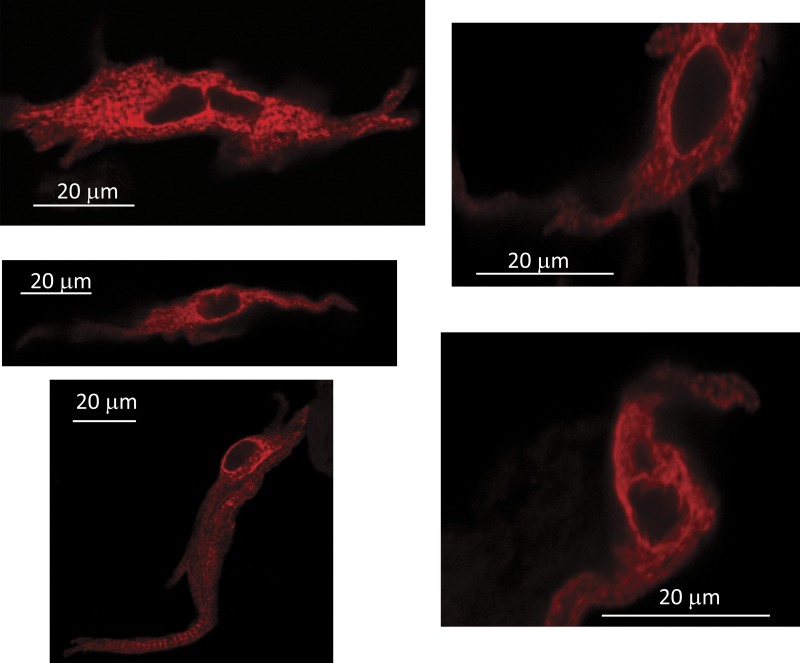
25 rabbit SANCs were studied. In all SANCs there was a concentration of RyR staining immediately below (within the resolution of confocal microscopy) the sarcolemma (see Fig. S1 for images of all cells). About half of the cells were essentially devoid of interior RyRs, as shown previously (Musa et al., 2002; Lyashkov et al., 2007). We chose to concentrate on those “hollow” cells (15 of 25 in Fig. S1) for the simple reason that it is easier and much faster to model CICR in them, as explained in Materials and methods and the Appendix. How they may differ anatomically and physiologically from other SANCs is not presently known, but there is a suggestion that these are smaller, more irregular cells that may be interior sinus node primary pacemaker cells (see Fig. 6 E in Musa et al., 2002).
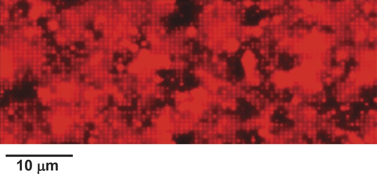
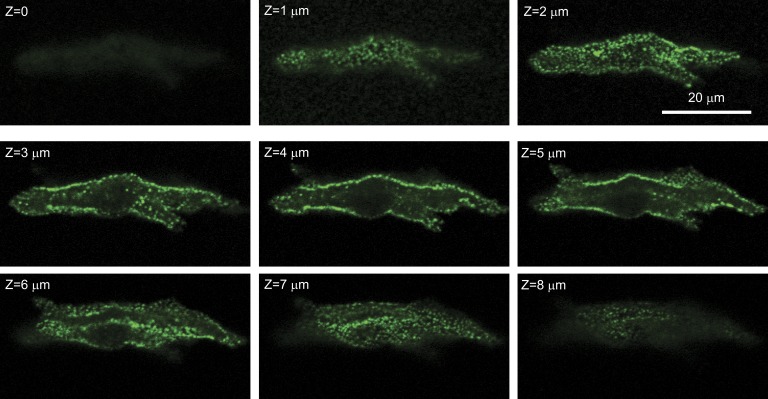
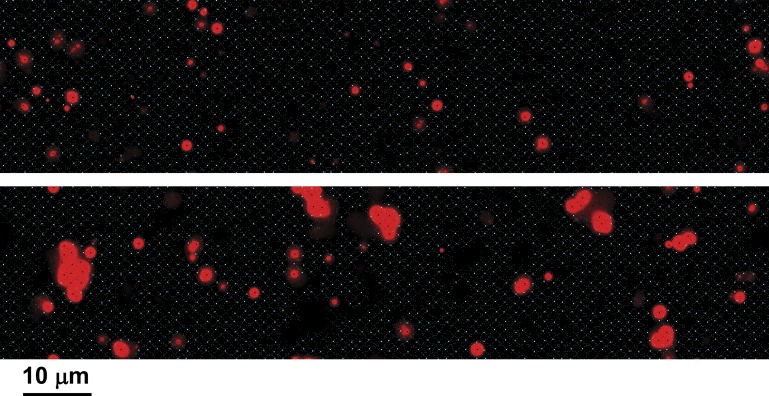
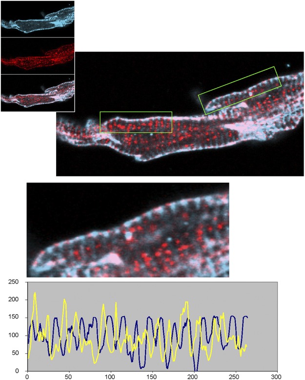
Fig. 7 shows serial confocal sections of a representative SANC. In cross sections, the clustering of RyRs at the surface and the absence of RyRs in the interior are easily seen. Of most interest, however, are the tangential sections at the top and bottom of the cell, where the topographic arrangement of RyRs in the plane of the surface membrane can be approximately seen. Clearly, RyR clusters are not regularly spaced nor are they all of the same size (or at least density at the resolution of light microscopy). Although there are regions that appear to have no RyRs, there are faint or small regions of positive RyR staining that appear to bridge the largest clusters. In Fig. S1, we show interior confocal sections of all 25 SANCs studied, indicating the ones that have minimal interior RyRs as modeled. Tangential sections of six of those cells for which sufficiently tangential cuts allowed analysis are shown in Supplement 2.
Figure 7.
Serial confocal sections of a SANC stained with fluorescent antibody to RyR. RyRs are limited to the surface membrane (this pattern was observed in 15 out of 25 cells). Tangential sections show that surface RyRs form an irregular network of large and small RyR clusters. Confocal sectioning was performed (along the z axis) with a step of 1 µm (Z = 0 at the bottom).
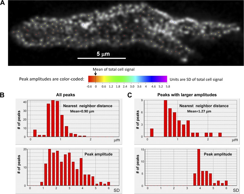
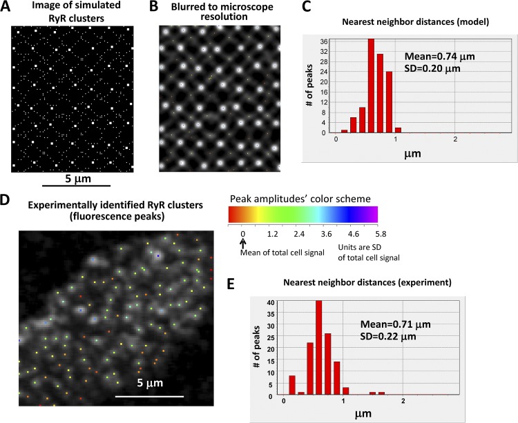
We visually interpreted this pattern as an irregular array of major clusters with minor clusters linking them in a network. We constructed histograms of nearest-neighbor distances (representative cell in Fig. 8; six cells shown in Supplement 2) by the following method: The SD of fluorescence intensity in the tangential section was computed (this SD was one to two orders of magnitude above the background level of a cell stained without primary antibody), and then the fluorescence image was sequentially binned at 33 levels expressed as multiples (bin = 0.2) of the SD, identifying (non-redundantly) discrete peaks that appeared within these bins at various levels. Histograms of nearest-neighbor distances were constructed for all peaks and for the subset of peaks at high amplitude. Among all peaks, nearest neighbors were found at submicrometer distances, whereas the largest clusters were spaced at distances on average comparable to those used in our previous 2-D models (see summary table in Supplement 2). Because not all bridging RyR regions constitute discrete local peaks, this method probably still underestimates the frequency of short propagation paths for CICR, as discussed below.
Figure 8.
Quantification of RyR cluster distribution on cell surface. Location of local peaks (A) in the image at Z = 2 µm (i.e., tangential section) by an algorithm described in Results, and histograms of their amplitudes and nearest-neighbor distances. (B and C) High amplitude peaks had separations typically >1 µm, but inclusion of minor peaks introduced submicrometer distances. Full analysis of six cells is presented in Supplement 2.
We simulated this pattern by an array of major RyR couplons (7 × 7; 210 nm in width) located on a “perturbed” rectangular array spaced 1.4 ± 0.2 µm in z and θ, interspersed with 3 × 3 couplons (90 nm, fitting within a single voxel) located ±0.1 µm from alternate voxel positions along diagonals through the major couplons. A typical resulting distribution of couplons is shown in Fig. 9. This gives a total of ∼196,000 RyRs per cell, which is ∼14% of the 1.4 × 10⁶ estimated to be present in a ventricular myocyte (Bers and Stiffel, 1993).
Figure 9.
Distribution of nearest-neighbor distances in our model is close to that measured experimentally. (A) An example of the network of large (7 × 7 RyRs) and small (3 × 3) couplons used in the model. (B) The same network of RyRs as in A but as it would be seen using a confocal microscope with diffraction-limited resolution of ∼200 nm. (C) Distribution of nearest-neighbor distances of the simulated image in B. (D and E) An example of experimentally measured RyR-labeled fluorescence (cell 10 bottom in Supplement 2), with the distribution being close to our simulated RyR distribution shown in C.
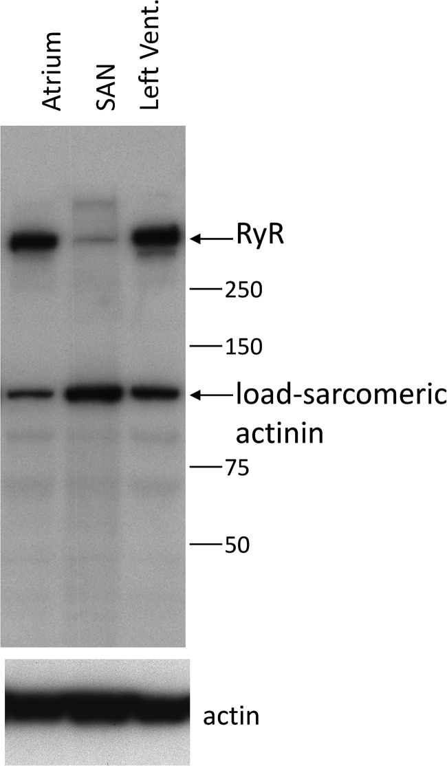
As a check on the realism of this construction, we compared the 3-D integrals of RyR immunofluorescence intensity in serial sections of SANCs and ventricular cells, adjusting for differences in magnification, pixel size, illumination-intensity pinhole size, and section thickness. This gave an integrated SANC fluorescence of 14.2% (on average, n = 10 cells) of that in ventricular myocytes, indicating that the density of RyRs in the model is probably comparable to that in SANCs. A similar comparison was derived from Western blots (Fig. 10).
Figure 10.
Western blot of rabbit tissues probed for RyR2 (clone C3-33 AB), consistent with the estimate that RyR density in SANCs is ∼14% of that in ventricular cells.
To verify that the scale of this network was comparable to that observed experimentally, we applied our peak-finding algorithm to the model distribution in Fig. 9 A after first blurring it to the diffraction-limited resolution of the confocal microscope (∼200 nm; Fig. 9 B). The distribution of nearest-neighbor distances (Fig. 9 C) was similar to that obtained from the experimental images (Fig. 9, D and E). The average nearest-neighbor spacing of large clusters in the model of 1.23 µm was also comparable to the experimental value of 1.27 ± 0.12 µm (mean ± SEM; n = 6 cells; table in Supplement 2). This value is less than the primary lattice period of 1.4 µm because of the intrinsic nonlinearity of the 2-D “nearest-neighbor” function. Of note, in the blurred images (Fig. 9 B), the peak-finding algorithm did not individually detect many of the minor clusters, which form sub-resolution bands bridging the major peaks. It is likely that the bridging densities between peaks in the experimental images may be similarly concealing sub-resolution clusters, although there is no way to determine, from these images, whether they correspond to the network of minor clusters used in the model.
The calcium clock in isolation
The random network model readily generates propagated LCR events. In beating SANCs, the calcium clock is normally activated during an up-sloping DD, starting from an SR that is relatively loaded with calcium by the L-type current of preceding beats. Fig. 11 and Video 3 show an attempt to emulate this environment in a free-running calcium clock. The cell is started from [Ca2+]SR = 1 mM and held at −50 mV, a typical potential late in diastole just before the onset of the L-type current that drives the upstroke of the action potential.
Figure 11.
Behavior of the calcium clock in isolation. The model cell was voltage clamped to −50 mV starting from a state with 1 mM of free calcium in the SR. The decaying oscillations actually consist of LCR events temporarily synchronized by the initial state. With time, LCR events become less synchronous, and cell calcium declines as a result of extrusion of calcium by NCX. The eventual steady state still consists of high calcium local events propagated over limited distances.
This results in a series of periodic decaying pulses of calcium release from the SR, in the whole-cell aggregate. Examination of the calcium images and video reveals that these are not actually damped harmonic oscillations. Rather, they consist of multifocal LCR events that form, expand, deplete the JSR locally, and then collide and/or decay. The initial pulse consists of wavelets that expand to cover the entire area of the cell until they collide. Because they are started synchronously, they terminate roughly synchronously, so that the relative refractoriness of couplons caused by local JSR depletion is approximately synchronous throughout the cell. The next “crop” of LCR events then begin partially synchronized, generating a second pulse of aggregate release. However, with each succeeding pulse, LCR events become increasingly desynchronized. The total cell calcium also becomes depleted because there are no action potentials or L-type current to replenish the loss of calcium via NCX. Eventually, an apparent steady-state develops, which actually consists of a continuing sparse “calcium chaos” (Fig. 11 and Video 3) of intense LCR events forming, propagating, and terminating locally, although the average cytosolic calcium concentration is low.
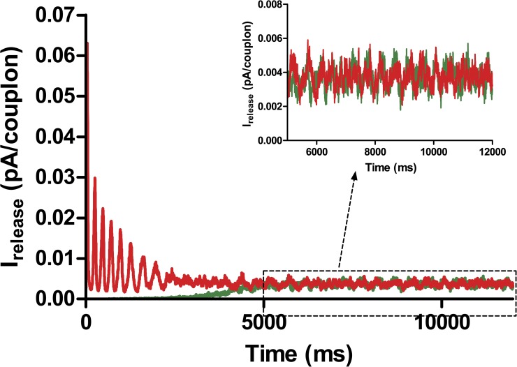
This dynamic steady state is more easily studied if the cell is clamped to −3 mV, a potential at which the “reverse mode” of NCX can bring calcium into the cell to establish an equilibrium loading condition. Fig. 12 shows the aggregate calcium release flux under these conditions, when the cell is started with a fully loaded (red) or depleted (green) SR. In the former case, a series of periodic releases occurs, but in either case the cell evolves to a steady state. As the inset shows, this state is not an equilibrium but a dynamic, random process with some degree of periodicity. Video 4 portrays the chaotic, high amplitude calcium fluctuations in the steady state.
Figure 12.
A voltage clamp of the isolated calcium system to −3 mV leads, after decaying oscillations, to a steady state in which average cytosolic calcium is in equilibrium with NCX. This steady state still consists of high amplitude chaotic calcium release events that persist indefinitely and have a partial periodicity.
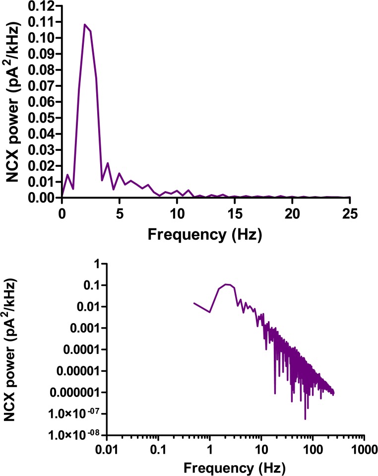
Examining the cross-sectional images reveals that the cytosolic calcium increase remains largely confined to a region near the surface of the cell, despite the absence of a confining subspace. This is because calcium diffusing into the inner cytosol will be captured by SERCA and returned, via diffusion within the FSR lumen, to the JSR release terminals. The complexity of this circulation is revealed in the images of FSR calcium. Fig. 13 shows the power spectrum of the NCX current that would be measured under voltage clamp. There is a clear peak at ∼2 Hz indicating partial periodicity, but the log–log plot reveals that the spectrum also has a high frequency tail that is approximately a power law with exponent between −2 and −3. The degree of periodicity of the free-running calcium “clock” in a prolonged steady state is not relevant to physiology, as the clock would normally be reset by the next action potential.
Figure 13.
The power spectrum of the steady-state NCX current generated by the chaotic calcium release shown in Fig. 12. The top shows a distinct peak at 2 Hz. On a log–log scale (bottom), it is seen that there is a tail of high frequency noise with a roughly power-law spectrum.
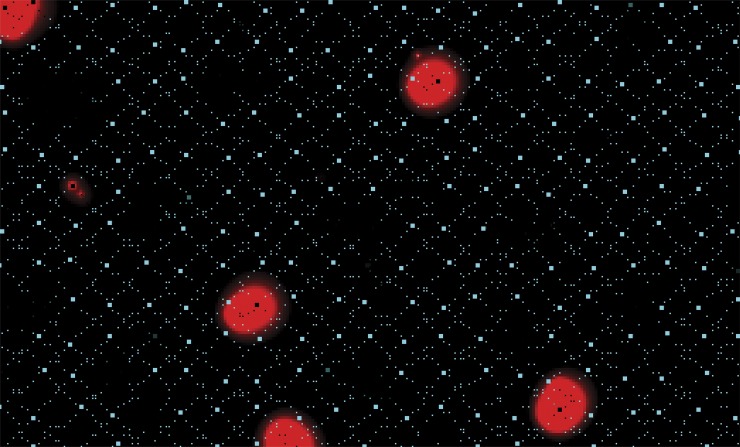
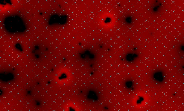
LCR events generated by the model take the form of locally propagated wavelets that do not extend to global waves, in agreement with experiments. Large-scale waves traveling at ∼100 µm/s can be produced by assuming higher calcium cooperativity of the RyR, thereby reducing spark and wave initiation rate, together with reduced SERCA pumping rate to extend the refractory period (not depicted), but do not occur under standard conditions. The mechanisms limiting the extent of propagation of LCR events are complex. At high calcium loading, LCR events collide and travel in corridors of excitable couplons, confined by regions of JSR depletion left by previously passing wavelets (Video 4). At low loads, e.g., the steady state during prolonged voltage clamp at −50 mV, LCR events remain small and isolated and appear to terminate spontaneously (Fig. 14 and Video 5). Although individual “sparks” terminate as a result of JSR depletion, the propagated LCR events produce a complex series of regional changes in FSR and JSR calcium. In the immediate vicinity of the LCR, FSR calcium is depleted, but this is surrounded by a halo in which uptake of cytosolic calcium by SERCA produces increased FSR calcium in advance of the leading edge of the wavelet (Fig. 15 and Video 6). Careful examination shows that the LCR terminates while there is still full loading of the JSR adjacent to the boundary of the wave. After extinction, there is actually a slight overshoot of JSR calcium in the border region caused by recycling of cytosolic calcium, and then a wider region of slight JSR depletion before recovery. The termination of these small LCR events is therefore not directly caused by regional SR depletion.
Figure 14.
Cytosolic calcium image (red) of limited-size LCR events produced in the steady state after depolarization to −50 mV. Calcium is shown on an enhanced scale (500 nM saturation, 100 nM black) to demonstrate that the LCR events terminate while still isolated, not by interaction. JSR calcium is shown in cyan.
Figure 15.
FSR (red) and JSR (cyan) calcium images, on a highly expanded scale, of the same simulation as that shown in Fig. 14 (560 µM saturation, 480 µM black). There is a complex pattern of FSR increase and decrease at different distances, but the events terminate without collision and while neighboring JSR is still substantially loaded.
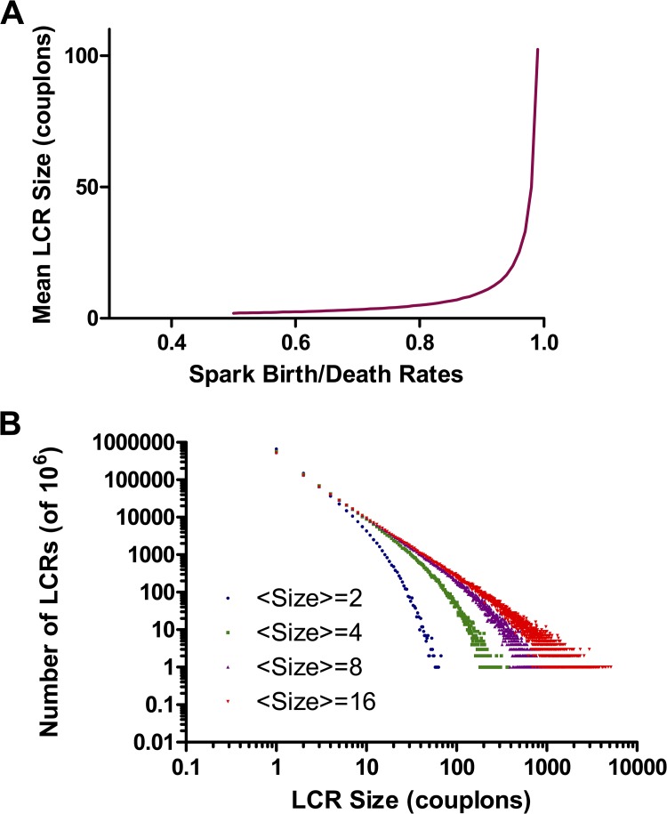
Two mechanisms may account for termination of small LCR events: Stochastic attrition and nearest-neighbor scarcity. At low JSR loading, the probability that the pulse of calcium released by a spark will ignite one of the neighboring couplons is borderline for sustained propagation, which can then fail because of random chance (stochastic attrition). We can model this crudely as a birth–death process in which each spark gives rise to triggered sparks at a rate b and dies (as a result of JSR depletion) at a rate d. The number of sparks will vary according to a Markov chain in which the next event is a birth with probability b/(b + d) and a death with probability d/(b + d). By constructing realizations of this chain, terminating when there remain no active sparks, we can build up a histogram of the “sizes” of LCR events, i.e., the total number of couplons activated before the LCR terminates, with b/d as a parameter. For b/d > 1, LCR events will grow indefinitely, i.e., until they collide. For b/d < 1, sparks terminate with a distribution of finite sizes. b/d = 1 is a critical point at which LCR events of any size can occur, with a power-law distribution of sizes. Fig. 16 A shows the mean size of LCR events as a function of b/d. By inverting this function, we can find b/d for a given observed mean LCR size, and construct the distribution of LCR sizes expected for this crude model of stochastic attrition (Fig. 16 B). For modest LCR sizes, the distribution has a “fat tail” that begins to approach a power law, which implies a significant probability of seeing LCR events much larger than the mean. For example, if the mean LCR excites 10 couplons, there is a 2% probability of sizes >100. From Video 5, it appears that LCR events have a limited size range, suggesting that this simple model of stochastic attrition is not a sufficient explanation for their termination.
Figure 16.
A simple stochastic attrition model of termination of small LCR events. LCR events grow by recruitment of neighboring couplons and shrink by extinction of the individual sparks. (A) Average total number of couplons recruited during the life of an LCR event, as a function of the ratio of the spark recruitment to extinction rates. (B) The probability distribution of LCR sizes at different birth/death ratios, with the curves labeled by the mean size from A. For modest average sizes, the distribution approaches a critical power law, suggesting that very large LCR events should be relatively frequent if stochastic attrition were the only mechanism causing LCR termination.
However, the couplon recruitment process is occurring on a discrete and irregular network. The number of nearest neighbors of an active spark will vary. In particular, as an LCR becomes larger and the radius of curvature of the active edge becomes larger than the typical spacing in the network, the number of available (nonrefractory) neighbors will decrease. This would tend to make random termination more likely for larger LCR events, which may explain the limited sizes observed.
The size of LCR events is also affected by the density of NCX. Fig. 17 compares LCR events when kncx = 17.5 pA/pF or 150, during a steady-state depolarization to −34 mV, the potential at which equilibrium cytosolic calcium would be 100 nM. The larger the kncx the smaller LCR events are and the shorter the distance they propagate. This is because NCX “steals” calcium from the submembrane cytosol, interrupting CICR from one couplon to its neighbor, as we described previously in the 2-D CRU-based model (Maltsev et al., 2013). This inhibition of CICR by NCX results in paradoxical effects of NCX expression level on beating rate.
Figure 17.
LCR propagation is inhibited by high NCX density. Both panels show LCR events in a steady-state depolarization to −34 mV, the voltage at which NCX would be in equilibrium with 100 nM of cytosolic calcium. In the top panel, kNCX is 150 mM/ms, whereas in the bottom panel, it is 17.5 (full red, 500 nM saturation; black, 100 nM minimum).
LCR events coupled to membrane currents
When all membrane currents are enabled, the LCR events entrain with the “membrane clock” to produce free-running action potentials at an accelerated rate compared with the membrane clock alone. Fig. 18 shows action potentials during steady-state beating in three situations: Fig. 18 A: no SR uptake or release; Fig. 18 B: intact SR uptake and release with reduced sensitivity of RyRs; and Fig. 18 C: intact SR function. For these examples, the “funny” pacemaker current If has been omitted to clarify the importance of calcium cycling for the DD. In the complete absence of SR function, action potentials are very slow and bizarre. This is a somewhat artificial situation, because the systolic release of SR calcium is absent. Therefore, relaxation of cytosolic calcium that entered via the L-type current must occur entirely by slow extrusion on NCX. In Fig. 18 B, systolic release is present but, because the sensitivity of RyRs has been reduced, there is minimal diastolic release or propagation of LCR events. In Fig. 18 C, the rate is markedly accelerated by the robust diastolic calcium release. The aggregate release flux increases during the last half of diastole, producing an inward contribution to the NCX current, driving the membrane toward threshold, as posited in the “coupled clock” theory. Spontaneous diastolic calcium release produces a qualitative difference in action potential formation, which may be seen by plotting phase–plane trajectories of voltage versus JSR calcium, aggregate calcium release flux, and INCX (Fig. 19). The difference in shape of these loops is obvious and can be traced to the trend of INCX during the period of diastole when Vm is less than −50 mV, i.e., before the onset of the L-type calcium current. In the absence of diastolic calcium release, INCX rises (becomes less inward) during diastole as the membrane becomes more depolarized. Spontaneous calcium release reverses this trend, accelerating the approach of Vm to threshold, thereby speeding up the beating rate.
Figure 18.
The calcium clock couples to membrane currents to drive faster beating rate. (A) In the absence of the SR (no uptake or release), there is slow beating. (B) When RyR sensitivity is low (20 µM IC50), systolic release occurs, altering the pattern of INCX; however, there is minimal diastolic release, and rate is not affected. (C) When RyRs have normal sensitivity, there is extensive diastolic release. This produces a diastolic inward NCX current, driving a substantial increase in beating rate. The “funny” current If was omitted from these simulations for illustrative purposes.
Figure 19.
Phase-plane loops of voltage versus NCX current, SR calcium release flux, and JSR calcium, for the conditions shown in Fig. 18 (A–C). In the presence of normal RyR sensitivity, diastolic release is apparent at voltages below −50 mV and alters the shape of the INCX loop, producing an inward (downward) slope at low voltages that drives the membrane to threshold.
Video 7 reveals that this rising diastolic release consists of multiple propagating LCR events that expand by recruitment of couplons, consistent with experimental observations (Hüser et al., 2000; Bogdanov et al., 2001; Maltsev et al., 2004). These then merge into the global release when the membrane reaches threshold to activate the L-type calcium current. The L-type current triggers release by a local control mechanism in each couplon, simultaneously depleting the JSR in all couplons, thereby resynchronizing the clocks. Note, however, that because some of the JSR release terminals are already partially depleted by the passage of an LCR, systolic release is inhomogeneous, so that the system has some local calcium “memory” from beat to beat (Video 8).
Beating rate regulation by the “calcium clock”
The coupled clocks hypothesis posits that the calcium clock provides a major pathway for the regulation of beating rate. In particular, it mediates the modulation of beating rate by the autonomic nervous system and stress hormones. Such modulation has been demonstrated to be mediated by phosphorylation of various proteins involved in calcium cycling, via cAMP-dependent PKA and other pathways, and probably reinforced by feedback via calcium-calmodulin kinase (CaMK-II) (Lakatta et al., 2010). Important phosphorylation sites exist on phospholamban (increasing the activity of the SERCA-2 pump), the L-type calcium channel (increasing ICaL), and the RyR (probably increasing its calcium sensitivity; Wehrens et al., 2005). We therefore examined the effects of such changes on the coupled model.
Paradoxical effect of NCX.
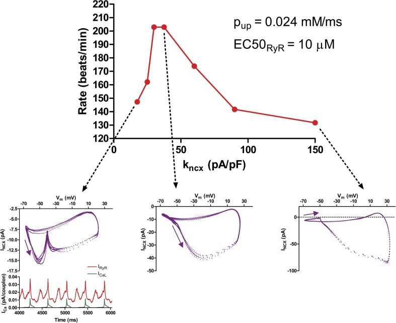
Before considering the effects of (virtual) phosphorylations, we need to examine the effect of NCX. NCX has paradoxical actions in the coupled model. On the one hand, the NCX current couples the calcium clock to the membrane voltage, so one might expect greater NCX density to enhance the DD caused by LCR events. On the other hand, as shown above, NCX can inhibit the propagation of LCR events by “stealing” subsarcolemmal calcium from the diffusing wave front. NCX density is difficult to measure, as it requires knowing simultaneously Vm, INCX, and subsarcolemmal calcium. Fig. 20 shows the net effect of varying kNCX on the beating rate of the coupled model. Over much of the range, reducing NCX density actually increases beating rate. At the lowest NCX densities, rate again declines. As shown by the insets, this is accompanied by a qualitative change in the relationship between the calcium clock and the membrane. Diastolic calcium release peaks early and declines (because of collision of LCR events and JSR depletion; see Video 9) before the membrane potential reaches threshold to activate the L-type current producing the upstroke of the action potential. This desynchronization of the clocks results in a bizarre Vm–INCX loop. The root cause is that the calcium clock “runs” faster than it can drive the membrane potential via the diminished NCX density.
Figure 20.
Biphasic variation of beating rate as a function of NCX density. At high NCX density, LCR events are suppressed, giving a low beating rate. However, for very low NCX densities, the calcium clock becomes desynchronized from the membrane, leading to diastolic release that peaks too early to trigger the action potential. This results in a characteristic “kink” in the NCX phase-plane loop and a lower beating rate. Note that INCX depends on calcium and voltage and so does not vary directly with kNCX. If was included in the model for this and later simulations examining rate regulation.
Rate modulation by RyR calcium sensitivity.
The RyR is known to be phosphorylated at serine 2808 and serine 2814 (by PKA and CaMK-II), which is believed to increase its calcium sensitivity (Huke and Bers, 2008), and RyR in SANCs was found to be phosphorylated at serine 2808 under basal conditions (Vinogradova et al., 2006). It may also be activated by oxidation or nitrosylation under pathological conditions (Wehrens et al., 2005). The concept of RyR sensitivity is somewhat poorly defined because its true gating scheme is unknown. For the purposes of this paper, we assume the simplistic two-state gating scheme that we used in our previous model of calcium spark dynamics (Stern et al., 2013). In this scheme, the open probability of the RyR is a Hill function, characterized by a cooperativity hry and a midpoint EC50 (at a lumenal free calcium concentration of 1 mM). For the simulations presented here, we assume a fixed open dwell time of 5 ms and an opening rate constant that diminishes linearly by 90% as the lumenal calcium is reduced to zero. For most cases, we assume hry = 2 and a benchmark value of 10 µM for EC50. The use of these choices, based on lipid bilayer studies (which are themselves highly variable) is discussed at length in Stern et al. (2013).
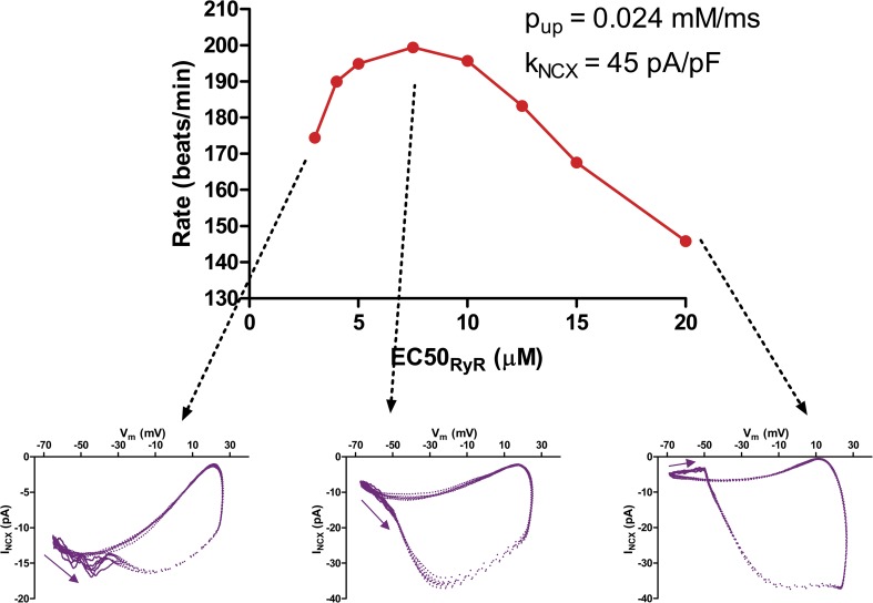
To study beating rate modulation by RyR sensitivity, we varied EC50, leaving other parameters constant. The effect of RyR sensitivity interacts strongly with NCX density and SERCA pumping rate. Fig. 21 shows the biphasic effect of EC50 on beating rate when SERCA Pup is 0.024 mM/ms and kNCX = 45 pA/pF. Increasing RyR sensitivity (decreasing EC50) speeds up beating until the point where EC50 has been reduced by ∼50% (for comparison, this is about the reduction brought about by 0.5–1.0 mM caffeine). Further increases in RyR sensitivity result in a slower beating rate. The accompanying phase–plane loops show that this is because of the onset of desynchronization of the calcium clock and membrane clock.
Figure 21.
Biphasic variation of beating rate as a function of RyR calcium sensitivity. Increasing RyR sensitivity increases rate up to a point, but higher sensitivity (lower IC50) produces a pathological premature diastolic calcium release, causing a kink in the phase-plane loop and paradoxical decrease in beating rate.
Rate modulation by SR pump rate.
The SR pump SERCA-2 is one of the major targets of β-adrenergic signaling, mediated by phosphorylation of phospholamban, which causes it to dissociate from SERCA, releasing inhibition of the pump. The kinetic effects of phospholamban removal are controversial. Most studies have suggested that it increases the cytosolic affinity of the pump for calcium, by about twofold, without affecting the Vmax (Akin and Jones, 2012). Other studies (Antipenko et al., 1999) indicate that both Vmax and affinity are increased. It should be noted that, if the pump normally operates at the thermodynamic limit, increasing the cytosolic affinity without changing the lumenal affinity would require an additional energy source. This may be accomplished by cooperative action of several SERCA-2 pumps, which are known to form oligomers (Mahaney et al., 2003).
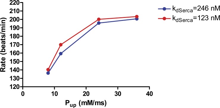
Fig. 22 shows the effect on the beating rate of varying Pup (i.e., Vmax) in the model, with or without a doubling of the cytosolic affinity. For these simulations, we assumed the “optimal” values of kNCX = 45 pA/pF and EC50 = 10 µM, with all other currents, including If, at their standard values. Increasing the pumping rate increases the beating rate as posited in the coupled clock theory, but the effect of affinity is comparatively small. The reasons for this are not entirely clear but may reflect the fact that SERCA is likely saturated at the high subsarcolemmal calcium concentrations during systole and early diastole, so that the additional pumping caused by increased affinity takes place too late in diastole to affect the onset and propagation of LCR events. SERCA at high affinity may also act to inhibit LCR propagation, as NCX does, by capturing diffusing calcium at the wave front.
Figure 22.
Increasing SERCA pumping rate increases beating rate, as proposed in the coupled clocks theory. The largest effect is produced by increasing the Vmax of the pump (represented by the model variable Pup), whereas increasing the pump affinity (red) makes a relatively modest contribution, possibly because of saturation of SERCA near the membrane.
When NCX density is low and/or RyR sensitivity is very high, increasing SERCA pumping rate can produce a paradoxical decrease in rate by bringing about desynchronization of calcium and membrane clocks (Fig. 23).
Figure 23.
Effect of increasing SERCA pump rate (as would be produced by β-adrenergic stimulation) in a model cell with increased RyR sensitivity. This introduces a pathological regimen in which further stimulation causes paradoxical decrease of the beating rate as a result of desynchronization of calcium and membrane clocks, producing the characteristic kink in the NCX phase-plane loop caused by premature diastolic calcium release.
DISCUSSION
Our simulations show that the coupled clock mechanism of SANC pacemaking can be qualitatively reproduced without resorting to heuristic mechanisms. However, in the absence of a confining subsarcolemmal space, propagation of CICR depends on a pattern of clustering of RyRs that includes submicrometer distances between couplons. Immunofluorescence staining showed that RyRs on the surface of SANCs in fact form a pattern of major and minor clusters with short distances among the minor clusters, which can act as a “fuse” to conduct CICR. A model based on a stylized rendering of this arrangement was able to reproduce observed, partially periodic LCR events, which entrained with the sarcolemma via sodium–calcium exchange current to regulate the beating rate. We found that under extreme conditions of RyR sensitivity or calcium loading, pathological desynchronization of the calcium and membrane clocks would occur, which causes paradoxical reversal of the β-adrenergic regulation of heart rate.
Work in our laboratory and in that of others has demonstrated that the DD of SANCs is driven, in part, by spontaneous SR calcium release, mediated via electrogenic NCX. This provides a major pathway for regulation of the heart rate. Although the quantitative contribution of this pathway in different species and circumstances remains controversial, its existence has rendered purely membrane-based models of SANC electrophysiology obsolete. We have proposed a “coupled clocks” theory in which the “membrane clock”—consisting of interacting membrane currents and voltage—is mutually entrained with a calcium clock based on the cycling of calcium between the SR and cytosol under the influence of CICR. A full, quantitative biophysical theory of this coupled system remains to be achieved.
Diastolic calcium release consists of LCR events, which are stochastic and locally propagated. These are larger than calcium sparks but do not generally propagate throughout the cell as do calcium waves in ventricular myocytes. Any mathematical/numerical model of automaticity in SANCs must explain the production and periodicity of LCR events and their coupling to the “membrane clock.”
Previously, we and others (Kurata et al., 2002; Maltsev and Lakatta, 2009; Severi et al., 2012) have presented scalar or “common pool” models that treat diastolic calcium release as a single flux from a single SR compartment via an aggregate RyR conductance. To make this system sufficiently responsive, it was necessary to divide the cytosol into a bulk compartment and a thin submembrane space. The dynamics of the RyR conductance included an inactivation process to prevent CICR regeneration from persisting indefinitely. With these heuristic devices, the model was remarkably effective in explaining many experimental observations about the variation of SANC beating rate as a function of calcium loading, SR pump rate, etc. It also demonstrated that the coupling of the calcium oscillator to the membrane enhanced the robustness of SANC beating, i.e., its ability to recover from disturbances and operate over a wide range of parameters (Maltsev and Lakatta, 2009, 2013). However, the common pool model was unable to explain the local or stochastic nature of LCR events. Further, the heuristic device of the subspace has no anatomical basis and implies, incorrectly, that calcium released anywhere beneath the membrane has equal access to all other submembrane sites throughout the cell. This aspect of the model has been criticized by Himeno et al. (2011), who showed that the residence time of calcium beneath the membrane was insufficient in the absence of an anatomical confinement.
Further progress toward understanding the operation of the calcium clock was made by Maltsev et al. (2011), who constructed a model in which stochastic “CRUs” were spaced on a 2-D 1.3-µm grid, coupled by calcium diffusion within a subspace. This “black box” model of CICR was able to generate propagated LCR events. Examining the properties of these LCR events as a function of the calcium release flux suggested that the periodicity of the calcium clock was best thought of as an emergent property related to the refractory interval of the CRUs rather than a true oscillator. However, this raised a new question, because this refractory period, which was imposed by fiat in the model, must, in reality, be explained by the dynamics of couplon-dense clusters of individual RyRs coupled by local CICR. How such a refractory period arises is itself a matter of some subtlety, as there is very little evidence for a strong inactivation of RyRs. Recent experimental and theoretical studies (Gillespie and Fill, 2013; Laver et al., 2013; Stern et al., 2013) have shown that individual isolated calcium sparks in ventricular myocytes can be terminated without inactivation, as a result of local depletion of the JSR release terminal. However, the robustness of this termination is contingent on the gating kinetics of the RyR and the diffusion rate of calcium within the SR lumen. In SANCs, on the other hand, individual couplons do not function in isolation but are coupled through both the cytosol and the SR network. How either propagation or local refractoriness emerges from this hierarchical cluster of individual channels is by no means obvious.
This study is intended as a semi-quantitative proof-of-principle of the coupled clocks hypothesis. The ultrastructure of the calcium system in SANCs has not been characterized, and numerous critical parameters are unknown. We have made plausible estimates of these parameters based on available information, or by analogy with ventricular myocytes or by using immuno-morphological data (Figs. 7, 8, A1, A2, and S1, and Supplement 2). For comparison, we have used the same kinetic formulations for membrane currents used in the previous Maltsev–Lakatta common pool model, although these are surely not the last word in SANC electrophysiology. For these reasons, we have not attempted to make quantitative fits to experiments, which is premature at this time.
The calcium clock depends on short paths for CICR
We originally assumed an architecture analogous to that used in the CRU model (Maltsev et al., 2011), with couplons placed on the surface in a regular grid of spacing 1.3–1.4 µm. Unlike in the CRU model—where there is a subspace and CRU sensitivity can be chosen arbitrarily—in the 3-D couplon model, maximum RyR sensitivity is limited by development of metastable continuous regeneration of local CICR in individual couplons (Stern et al., 2013). This made it impossible to achieve propagation of LCR events. We confirmed by a direct, deterministic simulation that the probability of a spark “jumping” from one couplon to the next in the absence of a subspace is minimal at that spacing because of the 3-D diffusion of calcium away from the surface and cytosolic buffering.
By confocal sectioning of immunofluorescent RyR stains, we were able to examine the actual distribution of RyRs on the surface of SANCs at the limits of conventional optical microscopy. Although the most intense areas of RyR staining are spaced at over 1-µm distances, their location is irregular, and there are fainter intermediate RyRs bridging the most intense spots to form an irregular network-like distribution (Fig. 8 and Supplement 2). We constructed a model distribution of major and minor couplons resembling the confocal images, as described in Materials and methods. As a check on the realism of this construction, we attempted to estimate the surface density of RyRs in SANCs from the non-quantitative immunofluorescence images by comparison with stains of ventricular myocytes done under the same conditions. This indicated that the average density of RyRs in our model network was comparable to reality. The critical feature of this distribution is the presence of some short inter-couplon distances that can act as a “fuse” to conduct CICR between major RyR clusters. Using a peak-finding algorithm, we constructed distributions of nearest-neighbor distances between “clusters” of RyR density in the immunofluorescence and compared them to the nearest-neighbor distribution produced from “images” of our model distribution, numerically blurred to the resolution of our confocal microscope. The overall distributions were quite similar, and the mean nearest-neighbor distances among all peaks and brightest peaks, respectively, were in agreement with experimental values. Although this validates the overall scale of our model network, it is noteworthy that many of the minor couplons that formed the bridges along which CICR is conducted in the model were not individually resolved in the blurred images. It is therefore likely that the fuzzy bridges in the immunofluorescence images also conceal small clusters that may be critical for the propagation of CICR. As described below, there is indirect, circumstantial evidence that this is the case.
The resulting model successfully generated LCR events that form, propagate for limited distances, and terminate with eventual restoration of the excitable state (i.e., full loading of the JSR) in their wake. In the absence of anatomical evidence for a subspace, this implies that the complex distribution of RyRs on the surface of SANCs is an adaptive feature needed to support the calcium clock in cells that lack interior RyRs, which form ∼50% of all isolated SANCs (Musa et al., 2002; Lyashkov et al., 2007, and Fig. S1). Although the detailed distribution of couplons, as we have envisioned, is not unique, its basic characteristics appear to be required. We attempted to construct a model in which couplons were situated only at the locations of peaks detected in immunofluorescence images (mapped over the surface of the model cell by a tiling process), with RyR numbers proportional to the local image intensity. This required large couplons ranging from 6 × 6 to 11 × 11, many of which proved to be metastable (Stern et al., 2013), remaining active well into diastole, and the propagation of LCR events was limited to local groups of near neighbors. This model (not depicted) was not successful in reproducing the experimental observations: There was no periodic self-synchronization, there was persistent systolic calcium release that decayed slowly throughout diastole, and, as a result, there was no entrainment of the rhythm or rate acceleration. This negative result is actually highly informative. The failure of this model provides circumstantial evidence that small (optically unresolved) clusters of RyRs providing short paths for CICR over an extended region are needed for the proper functioning of the calcium clock.
Although all SANCs are lacking in t-tubules, about half have interior RyR staining in a sarcomeric pattern. The role of these interior RyRs is unknown, and we did not model those cells, which will require more extensive computational resources. It is noteworthy that images appear to show a gap of several micrometers between surface and interior RyRs (Fig.1 A in Rigg et al., 2000, and Fig. S1) that might restrict inward propagation of CICR from the surface.
Dynamics of LCR events and calcium clock
The model calcium cycling system displays many of the observed characteristics of the calcium clock of SANCs. Starting from a fully loaded SR, under voltage clamp the model generates what appear to be damped calcium oscillations, which decay to a steady-state calcium cycling at a calcium load that depends on the holding potential. However, unlike common pool models, this is not an analogue oscillator but an emergent result of numerous independent high amplitude calcium wavelets. These initially self-synchronize by collision and then decay to a randomized state, becoming rarer and smaller as the cell calcium load declines if the holding potential is very negative, as observed experimentally (Vinogradova et al., 2004). However, even in the steady state, LCR events are individually high amplitude, forming a chaotic, fluctuating “calcium fibrillation” that continues indefinitely. Spectral analysis shows that this state has residual periodicity as well as a high frequency noise component with a roughly power-law spectrum. 3-D visualization of these wavelets reveals a complicated pattern in which calcium is released—causing local depletion of the JSR—spreads by diffusion laterally and inward in the cytosol, and is then captured by SERCA and pumped into the FSR, from which it eventually diffuses back to replenish the JSR of couplons that have become extinct. This keeps the wavelets confined beneath the surface of the cell, with the interior largely protected from changes in cytosolic and FSR calcium. The pattern of FSR calcium is particularly complicated. Near the leading edge of the wave, the FSR becomes locally depleted by feeding calcium into the newly emptied JSR, whereas ahead of the wave there is actually a transient, mild increase of FSR calcium caused by uptake of cytosolic calcium that has diffused ahead of the wave front. After an LCR event has terminated, this slight calcium increase transfers to the JSR surrounding the terminal edge of the wave, suggesting that wave termination is not caused by SR depletion ahead of the wave. The relative magnitude of SR depletion and overload phases must depend on the rates of calcium diffusion within the FSR and from FSR to JSR, which are a matter of controversy (see Picht et al., 2011, and Stern et al., 2013, for discussions of this topic).
If the cooperativity of RyR activation is high (either intrinsically or a result of hypothetical allosteric interactions among RyRs within the couplon) so that spark initiation rate is low, it is possible to obtain global waves that propagate throughout a significant fraction of the cell. However, assuming hry = 2, the default based on a consensus of studies in lipid bilayer from the laboratory of Michael Fill, localized LCR events that expand and travel for limited distances are the rule. The mechanism by which these terminate is complex and not entirely clear. When the SR load is high, wavelets continually collide and reform in a kind of calcium chaos (Video 2). At lower SR loads, LCR events may collide with the “ghosts” of previous LCR events, i.e., areas of residual SR depletion where an LCR has passed, forming dynamical corridors as seen in the 2-D CRU model (Maltsev et al., 2011). However, at negative holding potentials, where the cell is depleted of calcium, small LCR events form and dissipate continually even though they are isolated. What limits their growth is uncertain. Stochastic attrition obviously plays a role, but if it were the only factor we suspect that large LCR events would be more frequent than they appear to be, although this will require a more complete statistical characterization. Another factor may be the discrete nature of the excitable medium. When the radius of curvature of the growing LCR is small, an active spark has more nearest neighbors to recruit than when it is large compared with the spacing of couplons.
Entrainment of calcium and membrane clocks
The important test of a coupled clock model is whether the calcium cycling system will couple, via INCX, to the membrane currents in such a way that diastolic LCR events will drive the DD and control the beating rate. During steady-state beating, the cell must establish a balanced calcium economy in which the calcium entering via the L-type and T-type calcium currents in each beat is equal to the net calcium extruded by NCX over the entire cycle, at the beating rate established by the entire system. The calcium clock must remain entrained with the membrane clock, producing LCR events with appropriate timing to drive the membrane to threshold, and then be recharged by uptake and recycling of calcium by the distributed FSR and JSR in time for the next beat. In this situation, the calcium loads of the cell and of the various compartments are dependent variables, so intuition is a poor guide as to what effect the various parameters will have on beating rate. The model simulations show that the correct entrainment does take place for parameters within certain ranges, which are fortunately compatible with our prior estimates.
The role of NCX requires special notice. Because it provides the coupling between calcium and membrane clocks, its density must be large enough to provide the inward current required to drive the DD. On the other hand, extrusion of subsarcolemmal calcium by NCX inhibits the propagation of LCR events, so the density of NCX must be small enough to allow the calcium clock to operate effectively. As a result, the effect of varying NCX density on beating rate is biphasic, as noted in our recent study coupling membrane currents to the 2-D CRU model (Maltsev et al., 2013), and the action of all other parameters will be affected by the density of NCX.
Physiological and pathological rate regulation by the calcium clock
The coupled clock hypothesis proposes that autonomic and hormonal regulations of the heart rate take place mainly by alteration of the calcium clock. β-Adrenergic stimulation increases heart rate during fight-or-flight emergencies by activating PKA, which phosphorylates targets on the L-type calcium channel, phospholamban, and the RyR.
Our model demonstrated appropriate effects on beating rates for these changes. The effect of increasing the rate of the SERCA pump was quite pronounced, whereas the effect on beating rate of a twofold increase in pump affinity (believed to be the effect of removal of phospholamban) was much more modest. Varying the calcium sensitivity of the RyR (changing the IC50 of its po curve) had a major effect on beating rate. Increasing the L-type current also increased rate (not depicted). The most important finding from these simulations was that these parameters (NCX density, RyR sensitivity, SERCA pump rate, and L-type current) all interact. In particular, when NCX density is small, RyR sensitivity is high, or SERCA pumping is fast, there is a pathological regimen in which synchronization of the calcium and membrane clocks is disrupted. The calcium clock runs too fast, producing a large diastolic release that peaks and collapses before the membrane—driven by INCX—can reach threshold. This regimen may be recognized by a peculiar “kink” in the phase-plane relationship between voltage and INCX. In this regimen, the regulatory effects of further increasing SERCA pumping or RyR sensitivity are reversed, causing rate to decrease. Such a regimen may already have been observed experimentally (Neco et al., 2012). In a mouse models with an RyR2 or CASQ2 mutation producing increased calcium sensitivity and catecholaminergic polymorphic ventricular tachycardia, isoproterenol was found to cause slowed and arrhythmic beating of isolated SANCs, accompanied by prominent releases of calcium during mid-diastole as in our model. This regimen may be of clinical relevance, as patients carrying catecholaminergic polymorphic ventricular tachycardia mutations are often observed to have sinus node dysfunction. Whether a similar pathological regimen may exist in other conditions of high RyR sensitivity (such as hyperphosphorylation in heart failure) needs to be investigated.
Origin of periodicity of the calcium clock
It is worthwhile to consider more deeply the underlying source of the periodicity of the calcium clock. In common pool models, this derives from the restitution time of CICR, which depends on the rate of reloading of the SR and the dissipation of RyR inactivation. In the CRU model, the periodicity emerges from the collective action of multiple CRUs, but its ultimate source is the refractory period of the CRU, which limits the frequency with which stochastic noise can be amplified into macroscopic calcium signals. In our present, fully stochastic model, refractoriness is a property of the dynamics of couplons rather than being imposed. The timing element goes back to being the restitution of excitability of couplons. In the absence of RyR inactivation, restitution is caused by refilling of the JSR terminal. For a single couplon, restitution depends on diffusion from the local FSR to the JSR. On a macroscopic scale, it requires, in turn, uptake of calcium into the FSR by the SERCA pump and diffusion through the FSR lumenal network to surface voxels that feed the JSR. The important distinction from the common pool model is that restitution is local. Individual LCR events can form, extinguish, and restitute quasi-independently, giving rise to large amplitude fluctuations having only a small periodic component in their spectrum. What makes it possible to have a macroscopic periodic signal that can drive the membrane potential is synchronization of LCR events. In the beating cell, this is provided by the systolic calcium release that (largely) resets the local refractory state, so that restitution begins synchronously. In the absence of another systole, LCR events will self-synchronize by colliding and extinguishing simultaneously, allowing macroscopic periodicity to persist for a few cycles until synchronization decays because of stochastic drift. In the beating cell, the NCX current caused by the synchronized LCR event itself triggers the next systole, maintaining the mutual entrainment of the two clocks.
Relationship to wave propagation in ventricular myocytes
Although we believe this is the first study to simulate the dynamics of individual calcium channels and LCR events in SANCs, previous work on calcium waves in ventricular myocytes is relevant. Izu et al. (2006), using a 3-D cytosolic diffusion model with idealized CRUs, found that the formation of propagated waves was critically sensitive to the spacing between CRUs, as found again in our deterministic analysis (Fig. 3). Ventricular myocyte models have generally been based on CRUs located at z-lines of sarcomeres and spaced transversely at myofibrils. Because myofibrils are spaced more closely than sarcomeres under most conditions, this leads to model waves that are highly elliptical, extended in the transverse direction (Subramanian et al., 2001), as has also been found in more recent ventricular myocyte simulations using explicit RyR gating (Tuan et al., 2011). This is grossly unphysiological, as wave fronts in ventricular myocytes are observed to be spherical before colliding with cell boundaries. Subramanian et al. (2001) tried to resolve this paradox by showing that diffusion of injected fluorescein is anisotropic, being several times faster in the longitudinal direction, which had also been inferred from the shape of calcium sparks in an earlier study (Parker et al., 1996). It was not clear that this anisotropy of diffusion was sufficient in itself to fully mitigate the anisotropic spacing of release sites. A possible solution to this problem was suggested by Soeller and colleagues (Soeller et al., 2007, 2009; Li et al., 2010), who found by immunolabeling that there are frequent dislocations of the sarcomere pattern in ventricular myocytes, such that couplons may have smaller average spacing in three dimensions than the sarcomere length, allowing isotropic wave propagation. A recent 3-D simulation using explicit gating of RyRs (Nivala et al., 2012) also produces spherical waves, but that model uses an isotropic spacing of couplons at 1-µm separation in all directions, which sidesteps the problem. Our findings in SANCs suggest that the conduction of CICR by bridging subclusters might be an explanation for the sphericity of waves in ventricular cells.
Limitations and future work
To explore further the mechanisms of SANCs beating in silico, further work is needed, both to improve our knowledge of the underlying structure and electrophysiology, and to study the parameter space more widely. Specifically:
(a) The most important limitation of the model is that the true detailed distribution of couplons on the surface of the cell is not known and had to be estimated in an ad hoc manner. As explained in the Discussion, the operation of the calcium clock depends on the presence of small RyR clusters and short intercluster distances that cannot be resolved by conventional light microscopy. Super-resolution microscopic techniques could dramatically improve this situation and will be used in future quantitative models to construct the couplon network in detail from direct observations. In fact, recent observations by STED microscopy in atrial myocytes (Macquaide et al., 2014) have revealed hierarchical clustering of small groups of RyRs, as we have envisioned in our model.
(b) The ultrastructure of the SR in SANCs has not been characterized. The location and volumes of the JSR and FSR and the structure of the FSR network and its connection to the JSR need to be measured rather than assumed as we have done based on immunofluorescence and comparison to ventricular myocytes.
(c) There is evidence that the diffusion coefficient of free calcium in the dyadic cleft may differ by an order of magnitude from that in free solution (Tadross et al., 2013). As we showed in our study of spark termination (Stern et al., 2013), this value has a profound effect on the dynamics of a couplon and therefore will impact the collective behavior of CICR in the whole cell.
(d) We have used the same simple two-state gating scheme that we used in our previous simulation of spark termination to show that the operation of the calcium clock does not require more complex RyR behavior, such as inactivation. However, the true gating scheme of the RyR is undoubtedly more complicated and poorly known. The effect of different gating schemes on the behavior of the SANC model needs to be explored, as does the effect of hypothesized allosteric coupling among RyRs. It is also known (Ju et al., 2011) that IP3 receptors are present in SANCs and play a role in calcium handling and rate modulation. It is not presently known whether they are directly involved in propagation of CICR in LCR events.
(e) For purposes of comparison, we used the same system of calcium buffers and the same Hodgkin–Huxley-style formulations for membrane currents that were used by Maltsev and Lakatta (2009) (derived from a previous model by Kurata et al., 2002). However, many of these formulations are arbitrary and have not been rigorously documented in the same preparation (rabbit central sinus node cells). The fact that such equations can fit, even quantitatively, a limited set of experiments does not prove that they reflect correct underlying biophysics.
(f) In particular, the model needs to be rebuilt using a realistic gating scheme for the L-type calcium channel that incorporates modern knowledge about the mechanism of calcium inactivation via tethered calmodulin (Tadross et al., 2008).
(g) One of the major claims of the coupled clock theory is that the mutual entrainment of two systems gives greater robustness of the heartbeat in response to alterations of parameters or transient disturbances of the physiological state. To test this hypothesis requires examining the behavior of the model over a range of parameter space, as has been done for the common pool model (Kurata et al., 2012; Maltsev and Lakatta, 2013). We have not attempted to do that here because of the extensive amount of computation required.
(h) We have also not considered those SANCs that have interior RyRs. It is not known whether their role in the sinus node differs from the “hollow” cells we have modeled. Including interior RyRs is straightforward in principle but will require major coding changes and a large increase in the number of processors.
(i) Future studies need to consider the manifold feedback loops involving calcium, cAMP production, and phosphorylation pathways, e.g. CAMKII and PKI.
APPENDIX
Detailed methods
Architecture.
The model cell is assumed to be a cylinder of radius r0 (4 µm) and length nominally 100 µm. The volume of the cell is divided into voxels as shown in Fig. 1 B according to a heuristic algorithm that maintains the aspect ratio of a voxel ∼1 in the z (axial), r (radial), and θ (azimuthal) directions while increasing the size of voxels in the interior of the cell where gradients are expected to be small because there are no discrete sources. Voxels in the first (subsurface) layer are ∼100 nm in each direction. The entire cell is divided conceptually into slices of width wslice perpendicular to the axis (like a salami), with an integral number nslice of slices assigned to each of nprocs processors. For all the simulations in this paper, nprocs = 80 and nslice = 1. For all simulations except those in Videos 1 and 2, wslice = 1.4 µm, making the true length of the cell 112 µm. For Videos 1 and 2, wslice = 0.7 µm. All the voxels in the domain of a single processor are addressed linearly in such a way that voxels that abut the domain of the two neighboring processors are at the beginning and end, respectively, of the address space, minimizing the overhead caused by communication between processors.
SR.
The structure of the SR in SANCs has not been characterized ultrastructurally. Immunofluorescence (Fig. 7) shows that, in the cells we are modeling (15 out of 25 SANCs examined), RyRs are located mainly at the cell surface, within the limits of light microscopy (see Fig. S1 for high resolution images of all cells). We assumed that these are all located in surface junctions, and that these can be represented by a distribution of discrete couplons of various sizes, and that all JSR terminals are located in these surface junctions. An algorithm to identify the positions and amplitudes of peaks in the images confirmed the presence of minor RyR clusterings with submicrometer nearest-neighbor distances (Fig. 8 and Supplement 2 (six cells)) that served as the basis for a stylized distribution of couplons in the model. In the absence of other information, the ratio of the volume of a JSR terminal to the number of RyRs in the couplon was the same as in Stern et al. (2013), which was based on measurements in ventricular myocytes. On the other hand, immunofluorescence stains for SERCA-2 of 20 cells showed that it was located throughout the cell in all of them (data from five representative cells are shown Fig. A1). We therefore treated the FSR as a diffuse network throughout the volume of the cell, occupying a fractional volume of fvfsr = 0.035 in every voxel.
Figure A1.
Immunofluorescence of SERCA2a showing that FSR is distributed throughout the rabbit SANCs. 20 cells showed a similar staining pattern.
As discussed in Stern et al. (2013), diffusion and connectivity in the SR lumen are matters of controversy. Picht et al. (2011) estimated the diffusion coefficient of free calcium in the SR to be 0.06 µm2/ms. However, spark modeling based on that value gave blink recovery and spark restitution times that were too short, so it was necessary to assume that additional diffusional resistance/tortuosity reside in the short tubular nexi that connect the FSR to the JSR terminals (Brochet et al., 2005). The total diffusional resistance between the JSR and infinity was estimated to correspond to a JSR refilling rate constant (in the absence of CaSQ) of Dup = 0.05–0.15 ms−1. The corresponding functional architecture in SANCs is not known. For the studies in this paper, we somewhat arbitrarily assumed that calcium diffuses within the FSR compartment of all voxels with a diffusion coefficient of 0.028 µm2/ms, and that calcium diffuses to the JSR from neighboring (surface) voxels with a transfer rate constant of Dup = 0.3 ms−1 partitioned among those voxels in proportion to the fraction of the area of the couplon contained in each voxel. The JSR contains 30 mM of CaSQ-binding sites.
The SERCA pump is present uniformly throughout the cell, transferring calcium from the cytosolic to the FSR compartment of each voxel with a rate (per FSR volume) given by the reversible pump formulation of Shannon et al. (2004) (see Supplement 1 for equations).
RyRs.
RyRs are arranged in couplons as described in Materials and methods. We used the same minimal two-state RyR gating scheme as used in Stern et al. (2013). Gating rates are given by:
where the opening rate constant ko is expressed in terms of the midpoint calcium, EC50, of the steady-state open probability by ko = kom/EC50hry. [Ca2+]cleft is computed locally at the location of each RyR. The cooperativity of activation, hry, was either 2 or 3 in simulations described in Results, as indicated. The constant sloc0 defines the ratio of RyR activation rate with empty JSR to that when [Ca2+]JSR is 1 mM. Its value was 0.1 for all the simulations reported. The unitary current of the RyR was assumed to be proportional to the free calcium gradient between lumenal and cytosolic faces of the channel, with a value of 0.35 pA at [Ca2+]JSR = 1 mM.
L-type calcium channel.
For comparability, we used the same formulation for the L-type current as used in the Maltsev–Lakatta model (Maltsev and Lakatta, 2009), derived originally from Kurata et al. (2002). This represents the channel open probability as the product of the open probabilities of three Hodgkin–Huxley gates, for voltage activation, voltage inactivation, and calcium inactivation. Unlike other membrane currents, ICaL cannot be treated as an analogue current because the channel interacts directly with RyRs by local control in the dyadic cleft. We therefore converted the Hodgkin–Huxley formulation to an explicit eight-state gating scheme. By representing the state of each of the series gates by 0 (closed) or 1 (open), the state of the channel is represented as a three-digit binary number from 0 to 7, with state 7 being the only open state. Transition rates between states are then the activation and deactivation rates of individual gates in the original scheme, computed as a function of global membrane voltage and local [Ca2+]. Because the channel in the cleft is exposed to much higher local calcium (tens of micromolar) than in common pool models, the calcium inactivation rate constant had to be greatly reduced to obtain reasonable-looking currents. All other rates were kept the same as in Maltsev–Lakatta (see Supplement 1 for equations). It should be noted that this heuristic gating scheme does not represent current understanding of the mechanisms of activation and inactivation of the L-type channel and should be replaced in future iterations of the model.
NCX.
The NCX was represented by the same rather complicated formulation used in Maltsev–Lakatta (see Supplement 1 for equations), which is derived from Dokos et al. (1996). NCX was assumed to be uniformly distributed over the nonjunctional area of the cell membrane, responding to local cytosolic calcium in each voxel. The exclusion of NCX from membrane areas that are part of dyad junctions implies that overall NCX density should vary inversely with that of RyRs. As shown in Fig. A2, we found this to be the case in dual immunofluorescent stains. Charge moved by NCX was integrated continuously in each surface voxel, as an additional “cytosolic” dynamical variable, and the resulting NCX current summed over voxels at each global time step was taken as the INCX contribution to the membrane potentials.
Figure A2.
Immunofluorescence of RyR and NCX shows that their density is anti-correlated, i.e., consistent with our assumption that NCX is not present in the junctional part of the cell membrane in rabbit SANCs. The unit of length in the bottom panel x axis is 0.1 µm.
Cytosolic buffers.
A fraction fvcyto (0.46) of each voxel is occupied by cytosol containing calcium buffers, the remainder presumably containing SR, myofilaments, mitochondria, nucleus, and other organelles. This number derives from studies in working myocardium and has not been validated in SANCs. The system of cytosolic buffers was the same as in Maltsev–Lakatta, comprising calmodulin (diffusible) and troponin-C calcium- and magnesium-binding sites ([Mg2+] assumed constant). See Supplement 1 for equations.
Membrane currents.
Sarcolemmal membrane currents other than ICaL and INCX were described by ordinary differential equations exactly as in the Maltsev–Lakatta model (see Supplement 1 for equations).
Simulation algorithm.
The simulation program is an extension of the one used to compute calcium spark dynamics in Stern et al. (2013). The algorithm uses a custom hybrid operator splitting-like method. Three systems of differential equations are integrated quasi-synchronously: (1) reaction–diffusion of calcium and dye in each couplon, discretized on a 2-D 10-nm grid, coupled to stochastic gating of L-type and RyR channels; (2) partial differential equations for reaction and diffusion of cytosolic calcium and buffers, discretized on the custom nonuniform grid shown in Fig. 1 B, with diffusion terms represented by finite differences of neighboring voxels; (3) membrane voltage Vm and currents represented as a system of coupled ordinary differential equations. The relationship and calcium fluxes among JSR, couplons, and voxels are schematized in Fig. 1 C.
The algorithm operates as follows for one global time step (summarized in Fig. A3):
Figure A3.
Schematic of the simulation algorithm. At each global time step, there is sequential updating of (a) the stochastic dynamics of all couplons, (b) diffusion and buffering in all cytosolic voxels, and (c) membrane voltage and currents.
Start at time t = ti
Map boundary values to processors to left and right
Estimate diffusion fluxes by differencing nearest-neighbor voxels
Integrate membrane voltage and currents fro0+ Δt
Sequentially integrate/Monte Carlo all couplons/channels from ti to ti + Δt
Sequentially integrate all voxel variables from ti to ti + Δt
t = ti+1 = ti + Δt
All integrations are performed using several copies of the routine DDRIV3 (CMLIB, NIST), which implements the Gear–Tu stiff differential equation method with adaptive time step. Internal time steps are controlled by the routine itself to maintain stability/accuracy of the local integration or, in the case of couplons, to reach the next channel transition event.
The state of couplons is advanced by the same Monte Carlo algorithm described in Stern et al. (2013) and explained in detail in Stern et al. (1997), except that boundary values for cleft calcium and calcium bound to diffusible dye are taken from the containing voxels rather than from a global pool, and similarly for influx to the JSR from the FSR. In brief, a special copy of DDRIV3 has been modified to integrate the cleft reaction–diffusion equations together with a scaled channel transition rate, until the next Monte Carlo event occurs when the scaled total transition rate reaches a preselected random number. This is repeated until the boundary of the global time step is reached. This algorithm generates an exact realization of the high dimensional variable-rate Markov process describing the totality of channels in the couplon, coupled to voltage and local calcium.
The diffusion fluxes can be calculated in two different ways. In the conservative version of the model, the flux source supplied to the voxel integration is given by:
where u represents a diffusible substance (i.e., calcium or calcium bound to buffer), nnb indicates a sum over nearest neighbors of the voxel, and Dnnb is a composite diffusion constant including the geometric effects of area, volume, and center-to-center distance. This method conserves total calcium. However, because the difference is taken at the start of the global time step, it risks instability of the overall algorithm if Δt is too large. In particular, calcium can become negative if there is a strong gradient favoring efflux from the voxel at the start of the global time step. This is particularly a problem because we treat calcium buffering in the cytosol dynamically, so the rapid diffusion of free calcium makes the system very stiff.
The nonconservative version of the model computes the diffusion flux as:
with the difference being that influx from neighboring voxels is taken as a snapshot at the start of the global time step, but efflux is computed using the live value in the voxel during the integration. The adaptive stiff solver then maintains stability and prevents voxel calcium from going below zero, maintaining stability of the overall algorithm even for large time steps, although an excessive time step will compromise accuracy. We found that satisfactory accuracy for the semi-quantitative purposes of this study was achieved with a global time step of 0.05 ms, and the algorithm was very robust. In contrast, the conservative algorithm was only stable for global time steps of 0.005 ms or less. We therefore only used it for the situation in which the cell was “sealed” by setting NCX to zero, as in that case (Videos 1 and 2), the cumulative error in total cell calcium became significant for simulation times of seconds.
Implementation.
The generic algorithm is embodied in a Gentran template in the computer algebra language Macsyma (legacy; Symbolics). When run, the template queries the user for specifics of channel states, gating schemes, cytosolic variables, buffering equations, sarcolemmal current equations, etc., in algebraic form. Macsyma then builds a parallelized Fortran program embodying the specific model. The Fortran is compiled and linked with OpenMPI and run on 80 processors of the National Institutes of Health (NIH) Biowulf Linux cluster. Using 10 nodes with 8 processors each (2.8-GHz Intel E5462) with communication by 16 Gb/s Infiniband, each second of simulated time requires ∼30 min of processing (stable, nonconservative algorithm). Using 20 nodes, each with four 2.6-GHz AMD Opteron 285 coupled by 1-Gb/s Ethernet, processing times are 50% longer.
Single SANC isolation
Single spontaneously beating, spindle-shaped SANCs were isolated from 8–12-wk-old male New Zealand white rabbit hearts as described previously (Vinogradova et al., 2004). The study conformed to the Guide for the Care and Use of Laboratory Animals, published by the NIH. The experimental protocols were approved by the Animal Care and Use Committee of the NIH (protocol 034 LCS 2013). The rabbits weighed 1.8–2.5 kg and were deeply anaesthetized with sodium pentobarbital (50–90 mg/kg) injected to the central ear vein. The adequacy of anesthesia was monitored until reflexes to ear pinch and jaw tone were lost.
Western blotting
The left ventricular, atrial, and sinoatrial node tissues were homogenized and lysed for 30 min on ice with RIPA buffer (0.15 mol/L NaCl, 10 mmol/L Tris, pH 7.4, 1% NP-40, 0.1% SDS, 0.5% deoxycholate, and protease inhibitor cocktail; Roche). The lysates were centrifuged (25 min at 4°C at 25,000 g), and the supernatant was stored at −80°C. Protein extracts (10 µg/lane) were separated using precast NuPAGE gels (Invitrogen). Proteins were then transferred to a PVDF membrane (GE Healthcare). The membranes were blocked with 5% nonfat dry milk in Tris-buffered saline (20 mM Tris and 150 mM NaCl, pH 7.6) with 0.1% Tween 20 (TBST), incubated overnight with antibodies (RyR2; 1:2,500; clone C3-33; Thermo Fisher Scientific), and reprobed for sarcomeric actin (1:10,000; clone 5C5; Sigma-Aldrich) and sarcomeric actinin (1:1,000; clone EA-53; Sigma-Aldrich) diluted in TBST. Secondary antibodies were horseradish peroxidase conjugated (GE Healthcare). An enhanced chemiluminescence system (GE Healthcare) was used to detect the bound antibody.
Immunolabeling of isolated SANCs
Isolated cells were fixed with 2% formaldehyde in PBS (Sigma-Aldrich) and then permeabilized with 0.5–1% Triton X-100/PBS. Nonspecific cross-reactivity was blocked by incubating the samples for 4 h in 1% BSA/PBS (Jackson ImmunoResearch Laboratories, Inc.). The cells were then incubated with primary antibodies (mouse monoclonal anti-NCX [IgM; clone C2C12], anti-RyR [IgG1, clone C3-33], and anti-SERCA2 [IgG1, clone IID8]; Thermo Fisher Scientific) diluted in 1% BSA/PBS overnight, washed in PBS, and then incubated with appropriate fluorescence label–conjugated secondary antibodies (Jackson ImmunoResearch Laboratories, Inc.) and imaged with an inverted confocal microscope (LSM 510; Carl Zeiss) using an oil lens (Plan-Apo 63X/1.4; Carl Zeiss).
Supplementary Material
Acknowledgments
We would like to thank Professor Thomas Shannon and Professor Michael Fill of Rush University and Dr. Anna Maltsev from Bristol University for helpful discussions. This study used the high performance computational capabilities of the Biowulf Linux cluster at the National Institutes of Health (NIH; http://biowulf.nih.gov).
This research was supported by the Intramural Research Program of the NIH, National Institute on Aging.
The authors declare no competing financial interests.
Richard L. Moss served as editor.
Footnotes
Abbreviations used in this paper:
- CaSQ
- calsequestrin
- CRU
- calcium release unit
- DD
- diastolic depolarization
- FSR
- free SR
- JSR
- junctional SR
- LCR
- local calcium release
- NCX
- sodium–calcium exchanger
- SANC
- sinoatrial node cell
- SERCA
- sarco/endoplasmic reticulum Ca2+-ATPase
References
- Akin B.L., Jones L.R. 2012. Characterizing phospholamban to sarco(endo)plasmic reticulum Ca2+-ATPase 2a (SERCA2a) protein binding interactions in human cardiac sarcoplasmic reticulum vesicles using chemical cross-linking. J. Biol. Chem. 287:7582–7593 10.1074/jbc.M111.334987 [DOI] [PMC free article] [PubMed] [Google Scholar]
- Antipenko A., Spielman A.I., Kirchberger M.A. 1999. Kinetic differences in the phospholamban-regulated calcium pump when studied in crude and purified cardiac sarcoplasmic reticulum vesicles. J. Membr. Biol. 167:257–265 10.1007/s002329900490 [DOI] [PubMed] [Google Scholar]
- Bers D.M., Stiffel V.M. 1993. Ratio of ryanodine to dihydropyridine receptors in cardiac and skeletal muscle and implications for E-C coupling. Am. J. Physiol. 264:C1587–C1593 [DOI] [PubMed] [Google Scholar]
- Bogdanov K.Y., Vinogradova T.M., Lakatta E.G. 2001. Sinoatrial nodal cell ryanodine receptor and Na+-Ca2+ exchanger: Molecular partners in pacemaker regulation. Circ. Res. 88:1254–1258 10.1161/hh1201.092095 [DOI] [PubMed] [Google Scholar]
- Brochet D.X., Yang D., Di Maio A., Lederer W.J., Franzini-Armstrong C., Cheng H. 2005. Ca2+ blinks: Rapid nanoscopic store calcium signaling. Proc. Natl. Acad. Sci. USA. 102:3099–3104 10.1073/pnas.0500059102 [DOI] [PMC free article] [PubMed] [Google Scholar]
- DiFrancesco D., Noble D. 2012. The funny current has a major pacemaking role in the sinus node. Heart Rhythm. 9:299–301 10.1016/j.hrthm.2011.09.021 [DOI] [PubMed] [Google Scholar]
- Dokos S., Celler B., Lovell N. 1996. Ion currents underlying sinoatrial node pacemaker activity: A new single cell mathematical model. J. Theor. Biol. 181:245–272 10.1006/jtbi.1996.0129 [DOI] [PubMed] [Google Scholar]
- Fabiato A. 1983. Calcium-induced release of calcium from the cardiac sarcoplasmic reticulum. Am. J. Physiol. 245:C1–C14 [DOI] [PubMed] [Google Scholar]
- Gillespie D., Fill M. 2013. Pernicious attrition and inter-RyR2 CICR current control in cardiac muscle. J. Mol. Cell. Cardiol. 58:53–58 10.1016/j.yjmcc.2013.01.011 [DOI] [PMC free article] [PubMed] [Google Scholar]
- Guo T., Gillespie D., Fill M. 2012. Ryanodine receptor current amplitude controls Ca2+ sparks in cardiac muscle. Circ. Res. 111:28–36 10.1161/CIRCRESAHA.112.265652 [DOI] [PMC free article] [PubMed] [Google Scholar]
- Himeno Y., Toyoda F., Satoh H., Amano A., Cha C.Y., Matsuura H., Noma A. 2011. Minor contribution of cytosolic Ca2+ transients to the pacemaker rhythm in guinea pig sinoatrial node cells. Am. J. Physiol. Heart Circ. Physiol. 300:H251–H261 10.1152/ajpheart.00764.2010 [DOI] [PubMed] [Google Scholar]
- Huke S., Bers D.M. 2008. Ryanodine receptor phosphorylation at Serine 2030, 2808 and 2814 in rat cardiomyocytes. Biochem. Biophys. Res. Commun. 376:80–85 10.1016/j.bbrc.2008.08.084 [DOI] [PMC free article] [PubMed] [Google Scholar]
- Hüser J., Blatter L.A., Lipsius S.L. 2000. Intracellular Ca2+ release contributes to automaticity in cat atrial pacemaker cells. J. Physiol. 524:415–422 10.1111/j.1469-7793.2000.00415.x [DOI] [PMC free article] [PubMed] [Google Scholar]
- Izu L.T., Means S.A., Shadid J.N., Chen-Izu Y., Balke C.W. 2006. Interplay of ryanodine receptor distribution and calcium dynamics. Biophys. J. 91:95–112 10.1529/biophysj.105.077214 [DOI] [PMC free article] [PubMed] [Google Scholar]
- Izu L.T., Bányász T., Balke C.W., Chen-Izu Y. 2007. Eavesdropping on the social lives of Ca2+ sparks. Biophys. J. 93:3408–3420 10.1529/biophysj.107.112466 [DOI] [PMC free article] [PubMed] [Google Scholar]
- Ju Y.K., Liu J., Lee B.H., Lai D., Woodcock E.A., Lei M., Cannell M.B., Allen D.G. 2011. Distribution and functional role of inositol 1,4,5-trisphosphate receptors in mouse sinoatrial node. Circ. Res. 109:848–857 10.1161/CIRCRESAHA.111.243824 [DOI] [PubMed] [Google Scholar]
- Kurata Y., Hisatome I., Imanishi S., Shibamoto T. 2002. Dynamical description of sinoatrial node pacemaking: improved mathematical model for primary pacemaker cell. Am. J. Physiol. Heart Circ. Physiol. 283:H2074–H2101 [DOI] [PubMed] [Google Scholar]
- Kurata Y., Hisatome I., Shibamoto T. 2012. Roles of sarcoplasmic reticulum Ca2+ cycling and Na+/Ca2+ exchanger in sinoatrial node pacemaking: Insights from bifurcation analysis of mathematical models. Am. J. Physiol. Heart Circ. Physiol. 302:H2285–H2300 10.1152/ajpheart.00221.2011 [DOI] [PubMed] [Google Scholar]
- Lakatta E.G., Maltsev V.A., Vinogradova T.M. 2010. A coupled SYSTEM of intracellular Ca2+ clocks and surface membrane voltage clocks controls the timekeeping mechanism of the heart’s pacemaker. Circ. Res. 106:659–673 10.1161/CIRCRESAHA.109.206078 [DOI] [PMC free article] [PubMed] [Google Scholar]
- Laver D.R., Kong C.H., Imtiaz M.S., Cannell M.B. 2013. Termination of calcium-induced calcium release by induction decay: An emergent property of stochastic channel gating and molecular scale architecture. J. Mol. Cell. Cardiol. 54:98–100 10.1016/j.yjmcc.2012.10.009 [DOI] [PubMed] [Google Scholar]
- Li P., Wei W., Cai X., Soeller C., Cannell M.B., Holden A.V. 2010. Computational modelling of the initiation and development of spontaneous intracellular Ca2+ waves in ventricular myocytes. Philos Trans A Math Phys Eng Sci. 368:3953–3965 10.1098/rsta.2010.0146 [DOI] [PubMed] [Google Scholar]
- Lukyanenko V., Wiesner T.F., Gyorke S. 1998. Termination of Ca2+ release during Ca2+ sparks in rat ventricular myocytes. J. Physiol. 507:667–677 10.1111/j.1469-7793.1998.667bs.x [DOI] [PMC free article] [PubMed] [Google Scholar]
- Lyashkov A.E., Juhaszova M., Dobrzynski H., Vinogradova T.M., Maltsev V.A., Juhasz O., Spurgeon H.A., Sollott S.J., Lakatta E.G. 2007. Calcium cycling protein density and functional importance to automaticity of isolated sinoatrial nodal cells are independent of cell size. Circ. Res. 100:1723–1731 10.1161/CIRCRESAHA.107.153676 [DOI] [PubMed] [Google Scholar]
- Macquaide N., Tuan H.-T.M., Hotta J.-I., Sempels W., Lenaerts I., Holemans P., Hofkens J., Jafri S., Willems R., Sipido K.R. 2014. Structural and functional alteration of RyR clusters after remodeling in persistent atrial fibrillation. Biophys. J. 106:431a. [DOI] [PMC free article] [PubMed] [Google Scholar]
- Mahaney J.E., Albers R.W., Kutchai H., Froehlich J.P. 2003. Phospholamban inhibits Ca2+ pump oligomerization and intersubunit free energy exchange leading to activation of cardiac muscle SERCA2a. Ann. NY Acad. Sci. 986:338–340 10.1111/j.1749-6632.2003.tb07208.x [DOI] [PubMed] [Google Scholar]
- Maltsev V.A., Lakatta E.G. 2009. Synergism of coupled subsarcolemmal Ca2+ clocks and sarcolemmal voltage clocks confers robust and flexible pacemaker function in a novel pacemaker cell model. Am. J. Physiol. Heart Circ. Physiol. 296:H594–H615 10.1152/ajpheart.01118.2008 [DOI] [PMC free article] [PubMed] [Google Scholar]
- Maltsev V.A., Lakatta E.G. 2013. Numerical models based on a minimal set of sarcolemmal electrogenic proteins and an intracellular Ca2+ clock generate robust, flexible, and energy-efficient cardiac pacemaking. J. Mol. Cell. Cardiol. 59:181–195 10.1016/j.yjmcc.2013.03.004 [DOI] [PMC free article] [PubMed] [Google Scholar]
- Maltsev V.A., Vinogradova T.M., Bogdanov K.Y., Lakatta E.G., Stern M.D. 2004. Diastolic calcium release controls the beating rate of rabbit sinoatrial node cells: Numerical modeling of the coupling process. Biophys. J. 86:2596–2605 10.1016/S0006-3495(04)74314-3 [DOI] [PMC free article] [PubMed] [Google Scholar]
- Maltsev A.V., Maltsev V.A., Mikheev M., Maltseva L.A., Sirenko S.G., Lakatta E.G., Stern M.D. 2011. Synchronization of stochastic Ca2+ release units creates a rhythmic Ca2+ clock in cardiac pacemaker cells. Biophys. J. 100:271–283 10.1016/j.bpj.2010.11.081 [DOI] [PMC free article] [PubMed] [Google Scholar]
- Maltsev A.V., Yaniv Y., Stern M.D., Lakatta E.G., Maltsev V.A. 2013. RyR-NCX-SERCA local cross-talk ensures pacemaker cell function at rest and during the fight-or-flight reflex. Circ. Res. 113:e94–e100 10.1161/CIRCRESAHA.113.302465 [DOI] [PMC free article] [PubMed] [Google Scholar]
- Musa H., Lei M., Honjo H., Jones S.A., Dobrzynski H., Lancaster M.K., Takagishi Y., Henderson Z., Kodama I., Boyett M.R. 2002. Heterogeneous expression of Ca2+ handling proteins in rabbit sinoatrial node. J. Histochem. Cytochem. 50:311–324 10.1177/002215540205000303 [DOI] [PubMed] [Google Scholar]
- Neco P., Torrente A.G., Mesirca P., Zorio E., Liu N., Priori S.G., Napolitano C., Richard S., Benitah J.P., Mangoni M.E., Gómez A.M. 2012. Paradoxical effect of increased diastolic Ca2+ release and decreased sinoatrial node activity in a mouse model of catecholaminergic polymorphic ventricular tachycardia. Circulation. 126:392–401 10.1161/CIRCULATIONAHA.111.075382 [DOI] [PMC free article] [PubMed] [Google Scholar]
- Nivala M., Ko C.Y., Nivala M., Weiss J.N., Qu Z. 2012. Criticality in intracellular calcium signaling in cardiac myocytes. Biophys. J. 102:2433–2442 10.1016/j.bpj.2012.05.001 [DOI] [PMC free article] [PubMed] [Google Scholar]
- Parker I., Zang W.J., Wier W.G. 1996. Ca2+ sparks involving multiple Ca2+ release sites along Z-lines in rat heart cells. J. Physiol. 497:31–38 [DOI] [PMC free article] [PubMed] [Google Scholar]
- Picht E., Zima A.V., Shannon T.R., Duncan A.M., Blatter L.A., Bers D.M. 2011. Dynamic calcium movement inside cardiac sarcoplasmic reticulum during release. Circ. Res. 108:847–856 10.1161/CIRCRESAHA.111.240234 [DOI] [PMC free article] [PubMed] [Google Scholar]
- Ramay H.R., Liu O.Z., Sobie E.A. 2011. Recovery of cardiac calcium release is controlled by sarcoplasmic reticulum refilling and ryanodine receptor sensitivity. Cardiovasc. Res. 91:598–605 10.1093/cvr/cvr143 [DOI] [PMC free article] [PubMed] [Google Scholar]
- Rigg L., Heath B.M., Cui Y., Terrar D.A. 2000. Localisation and functional significance of ryanodine receptors during β-adrenoceptor stimulation in the guinea-pig sino-atrial node. Cardiovasc. Res. 48:254–264 10.1016/S0008-6363(00)00153-X [DOI] [PubMed] [Google Scholar]
- Severi S., Fantini M., Charawi L.A., DiFrancesco D. 2012. An updated computational model of rabbit sinoatrial action potential to investigate the mechanisms of heart rate modulation. J. Physiol. 590:4483–4499 10.1113/jphysiol.2012.229435 [DOI] [PMC free article] [PubMed] [Google Scholar]
- Shannon T.R., Wang F., Puglisi J., Weber C., Bers D.M. 2004. A mathematical treatment of integrated Ca dynamics within the ventricular myocyte. Biophys. J. 87:3351–3371 10.1529/biophysj.104.047449 [DOI] [PMC free article] [PubMed] [Google Scholar]
- Smith G.D., Keizer J.E., Stern M.D., Lederer W.J., Cheng H. 1998. A simple numerical model of calcium spark formation and detection in cardiac myocytes. Biophys. J. 75:15–32 10.1016/S0006-3495(98)77491-0 [DOI] [PMC free article] [PubMed] [Google Scholar]
- Sobie E.A., Dilly K.W., dos Santos Cruz J., Lederer W.J., Jafri M.S. 2002. Termination of cardiac Ca2+ sparks: An investigative mathematical model of calcium-induced calcium release. Biophys. J. 83:59–78 10.1016/S0006-3495(02)75149-7 [DOI] [PMC free article] [PubMed] [Google Scholar]
- Soeller C., Crossman D., Gilbert R., Cannell M.B. 2007. Analysis of ryanodine receptor clusters in rat and human cardiac myocytes. Proc. Natl. Acad. Sci. USA. 104:14958–14963 10.1073/pnas.0703016104 [DOI] [PMC free article] [PubMed] [Google Scholar]
- Soeller C., Jayasinghe I.D., Li P., Holden A.V., Cannell M.B. 2009. Three-dimensional high-resolution imaging of cardiac proteins to construct models of intracellular Ca2+ signalling in rat ventricular myocytes. Exp. Physiol. 94:496–508 10.1113/expphysiol.2008.043976 [DOI] [PubMed] [Google Scholar]
- Stern M.D., Kort A.A., Bhatnagar G.M., Lakatta E.G. 1983. Scattered-light intensity fluctuations in diastolic rat cardiac muscle caused by spontaneous Ca++-dependent cellular mechanical oscillations. J. Gen. Physiol. 82:119–153 10.1085/jgp.82.1.119 [DOI] [PMC free article] [PubMed] [Google Scholar]
- Stern M.D., Pizarro G., Ríos E. 1997. Local control model of excitation–contraction coupling in skeletal muscle. J. Gen. Physiol. 110:415–440 10.1085/jgp.110.4.415 [DOI] [PMC free article] [PubMed] [Google Scholar]
- Stern M.D., Song L.S., Cheng H., Sham J.S., Yang H.T., Boheler K.R., Ríos E. 1999. Local control models of cardiac excitation–contraction coupling. A possible role for allosteric interactions between ryanodine receptors. J. Gen. Physiol. 113:469–489 10.1085/jgp.113.3.469 [DOI] [PMC free article] [PubMed] [Google Scholar]
- Stern M.D., Ríos E., Maltsev V.A. 2013. Life and death of a cardiac calcium spark. J. Gen. Physiol. 142:257–274 10.1085/jgp.201311034 [DOI] [PMC free article] [PubMed] [Google Scholar]
- Subramanian S., Viatchenko-Karpinski S., Lukyanenko V., Györke S., Wiesner T.F. 2001. Underlying mechanisms of symmetric calcium wave propagation in rat ventricular myocytes. Biophys. J. 80:1–11 10.1016/S0006-3495(01)75991-7 [DOI] [PMC free article] [PubMed] [Google Scholar]
- Tadross M.R., Dick I.E., Yue D.T. 2008. Mechanism of local and global Ca2+ sensing by calmodulin in complex with a Ca2+ channel. Cell. 133:1228–1240 10.1016/j.cell.2008.05.025 [DOI] [PMC free article] [PubMed] [Google Scholar]
- Tadross M.R., Tsien R.W., Yue D.T. 2013. Ca2+ channel nanodomains boost local Ca2+ amplitude. Proc. Natl. Acad. Sci. USA. 110:15794–15799 10.1073/pnas.1313898110 [DOI] [PMC free article] [PubMed] [Google Scholar]
- Terentyev D., Viatchenko-Karpinski S., Valdivia H.H., Escobar A.L., Györke S. 2002. Luminal Ca2+ controls termination and refractory behavior of Ca2+-induced Ca2+ release in cardiac myocytes. Circ. Res. 91:414–420 10.1161/01.RES.0000032490.04207.BD [DOI] [PubMed] [Google Scholar]
- Tuan H.T., Williams G.S., Chikando A.C., Sobie E.A., Lederer W.J., Jafri M.S. 2011. Stochastic simulation of cardiac ventricular myocyte calcium dynamics and waves. Conf. Proc. IEEE Eng. Med. Biol. Soc. 2011:4677–4680 [DOI] [PMC free article] [PubMed] [Google Scholar]
- Vinogradova T.M., Zhou Y.Y., Maltsev V., Lyashkov A., Stern M., Lakatta E.G. 2004. Rhythmic ryanodine receptor Ca2+ releases during diastolic depolarization of sinoatrial pacemaker cells do not require membrane depolarization. Circ. Res. 94:802–809 10.1161/01.RES.0000122045.55331.0F [DOI] [PubMed] [Google Scholar]
- Vinogradova T.M., Lyashkov A.E., Zhu W., Ruknudin A.M., Sirenko S., Yang D., Deo S., Barlow M., Johnson S., Caffrey J.L., et al. 2006. High basal protein kinase A-dependent phosphorylation drives rhythmic internal Ca2+ store oscillations and spontaneous beating of cardiac pacemaker cells. Circ. Res. 98:505–514 10.1161/01.RES.0000204575.94040.d1 [DOI] [PubMed] [Google Scholar]
- Wehrens X.H., Lehnart S.E., Marks A.R. 2005. Intracellular calcium release and cardiac disease. Annu. Rev. Physiol. 67:69–98 10.1146/annurev.physiol.67.040403.114521 [DOI] [PubMed] [Google Scholar]
Associated Data
This section collects any data citations, data availability statements, or supplementary materials included in this article.


