Abstract
Segmentation of interstitial catheters from MRI needs to be addressed in order for MRI-based brachytherapy treatment planning to become part of the clinical practice of gynecologic cancer radiotherapy. This paper presents a validation study of a novel image-processing method for catheter segmentation. The method extends the distal catheter tip, interactively provided by the physician, to its proximal end, using knowledge of catheter geometry and appearance in MRI sequences. The validation study consisted of comparison of the algorithm results to expert manual segmentations, first on images of a phantom, and then on patient MRI images obtained during MRI-guided insertion of brachytherapy catheters for the treatment of gynecologic cancer. In the phantom experiment, the maximum disagreement between automatic and manual segmentation of the same MRI image, as computed using the Hausdorf distance, was 1.5 mm, which is of the same order as the MR image spatial resolution, while the disagreement between automatic segmentation of MR images and “ground truth”, manual segmentation of CT images, was 3.5 mm. The segmentation method was applied to an IRB-approved retrospective database of 10 interstitial brachytherapy patients which included a total of 101 catheters. Compared with manual expert segmentations, the automatic method correctly segmented 93 out of 101 catheters, at an average rate of 0.3 seconds per catheter using a 3GHz Intel Core i7 computer with 16 GB RAM and running Mac OS X 10.7. These results suggest that the proposed catheter segmentation is both technically and clinically feasible.
Keywords: validation, segmentation, catheter, MRI
1 Introduction
Gynecologic malignancies, which include cervical, endometrial, ovarian, vaginal and vulvar cancers, cause significant mortality in women worldwide. In the United States, the number of gynecologic cancers has been increasing in recent years, while the death rate has remained relatively steady at about 35% of incidence [1]. The standard-of-care treatment for many primary and recurrent gynecologic cancers consists of chemoradiation (concurrent chemotherapy and external-beam radiation) followed by brachytherapy. In contrast to external-beam radiation treatment, in which a linear accelerator aims radiation beams at the pelvis from outside the body, in high dose rate (HDR) brachytherapy, sources that deliver high doses of radiation are placed directly inside the cancerous tissue using intracavitary applicators or interstitial applicators with catheters.
MRI is used routinely in the diagnosis of cervical cancer due to its increased tumor-to-normal-tissue contrast, scaled by noise (CNR) relative to CT. There is an increasing interest in expanding the role of MRI beyond diagnosis and into HDR treatment planning because of early results indicating it may lead to more precise treatment of the tumor and a reduction in the radiation dose to healthy tissue [2]. However, the deployment of MRI based gynecologic cancer brachytherapy treatment planning is not without challenges. In addition to the expense involved with running an MR-based clinical practice compared to the current standard-of-care, CT, there are companion technical, and specifically image analysis challenges, that have been acknowledged by international radiotherapy societies. Specifically, the GYN GEC ESTRO guidelines note that due to the steep brachytherapy dose gradients, catheter identification errors can lead to major dose deviations in both the target tumor, as well as neighboring tissues. While the source channels are well visualized in CT images, the task is more challenging and error prone when using MR images [3]. In a typical treatment, the radiation oncologist places several catheters using a transperineal approach, spaced about a centimeter apart, and these catheters can bend as they perforate stiff tissues along the insertion path. The “gold-standard” CT catheter visualization method involves placing copper wires, which have large CT absorption cross-sections, into the catheters at the end of the insertion process, with the resulting CT images segmented in brachytherapy treatment planning clinics. In contrast, distinguishing catheters from other signal voids in MRI is challenging, and requires dedicated MRI sequences that provide magnetic susceptibility artifacts that are controlled in their dimensions and directions integrated with sequence-specific image analysis. This paper presents a catheter segmentation method and validates its results in phantoms and clinical cases.
1.1 Related Work
Catheter artifact segmentation from MRI has primarily been pursued in the context of MR-guided interventions such as biopsy or radio-frequency ablation. In contrast to x-ray based imaging, where the material of the catheter is the main factor that influences its visibility, the success of this segmentation task when using MRI is heavily dependent on the MR imaging parameters, the sensitivity of the imaging sequence to magnetic susceptibility effects, and the direction of the catheter relative to the static magnetic field [5, 6]. Quantifying these differences in the catheter tip locations from MR sequences optimized for susceptibility imaging, based on the shaft orientation, demonstrated a 4–5 mm difference when the direction of the catheter was parallel vs. perpendicular to the direction of the static magnetic field [7]. Once satisfactory imaging sequences and parameters are selected, the segmentation of these catheters is typically performed using a Hough transform, and it is frequently suggested in the literature that this step could use improvement because catheters tend to bend as they are inserted into the body. Methods that enhance vessel-like structures using eigenvalues of the Hessian matrix have been successful for pre-processing contrast-enhanced images (MRA, CTA) [8, 9] but the results were not very useful for our MR images, which were acquired without contrast. While not developed for MRI (or 3D imagery), a method for catheter detection that is closest in approach to ours was reported in [10] for segmentation of catheters from 2D B-mode ultrasound images. It relies on the use of a Hough Transform to provide a set of points along the catheter path, and then polynomial regression to fit a curve to the catheter data, thus adequately capturing the bending of the catheter.
2 Methods and Materials
MR Imaging Sequence and Catheter Appearance
Three MRI sequences – Two-dimensional (2D) T2-weighted Fast Spin Echo (FSE), Three-dimensional (3D) FSE (Siemens SPACE), and 3D balanced steady state free precession (3D bSSFP) - were used to acquire the patient data in a 3 Tesla MRI (Siemens Healthcare, Erlangen, Germany). The tungsten-alloy filled, MRI-safe plastic catheters appear as signal voids of differing size, with the 2D FSE and 3D SPACE providing smaller artifact dimensions. The 2D T2-weighted FSE parameters were TR/TE = 3000/120 msec, 0.2×0.3×2.0 mm3. The SPACE parameters were TR/TE = 3000/160 msec, 0.4×0.4×1.0 mm3. 3D b-SSFP MRI sequence with TR/TE = 5.8/2.9 msec, 0.6×0.6×1.6 mm3 resolution, was used for rapid imaging (1.5 min/volume).
Phantom Construction
To validate the geometry of the extracted catheters, a phantom as shown in Figure 1, was constructed using commercially available transparent gel wax. An obturator, the long cylindrical component of an interstitial applicator assembly that holds the catheters in place, was placed at the center of a transparent plastic container, and gel wax was melted and poured around it. A Syed-Neblett template was then affixed orthogonal to the obturator at the edge of the plastic container. Catheters were inserted to mimic clinical scenarios, with some inserted straight, others bent, and some touching each other.
Fig. 1.
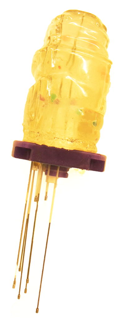
Gel Wax Phantom
Image-based Catheter Segmentation
The goal of the algorithm is to segment catheters of diameter 1.6 mm, length upto 240 mm, that may be straight or bent in configuration. In essence, starting with a manually provided catheter tip, the segmentation algorithm iteratively searches the image for a direction that maximizes the likelihood of 1.6 mm-diameter signal voids in a conic region, and fits Bézier curves to the end points of these segments. Implementation of the algorithm is described next.
Segmentation Algorithm Implementation
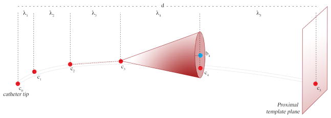
As illustrated in Figure 2, each catheter is represented as a curve with 6 control points. ci denotes the ith control point on the catheter; c0 is the distal end of the cather or the catheter tip, as provided by the user, and c5 lies on the proximal template plane, P, defined by the user
d is the length of the segment from tip c0 to the proximal plane P.
- λi is the height of the search cone for each successive control point. λi values were chosen to be increasing in magnitude, and the increases related to the Fibonnaci sequence4 as follows:
(1) - bi is the center of the base of the search cone for the ith point. These centers are computed as follows:
(2) ri is the radius of the ith search cone and is defined as an increasing series similar to λi.
- ci is computed by a search; it is the end point of the line segment that starts at ci−1 and has the minimal value for the intensity line integral along its length, among all choices in the search cone defined by bi, ri, and ci−1. After the control points are obtained, a 5th degree Bézier curve is computed as a linear combination of the Bernstein basis polynomial, in which the first and last control points define the extremity of the curve while the interior points pull the curve toward them:
(3)
Fig. 2.
Segmenting the catheter, one line-segment at a time. The user-defined catheter tip c0, and the plane, P, of the template where all catheters enter the body. The algorithm first finds points along the catheter by searching in conic regions of increasing height and radius, and then fits a Bézier curve to these.
3 Validation Experiments, Metric, and Results
The segmentation method was validated in three steps. The first two steps utilized the phantom, and the third used patient images. In the phantom experiments, first the disagreement between automatic and manual segmentation of the 12 catheters from the same MR image was computed. Second, this disagreement computation was repeated between automatic segmentation of catheters in MR images and “gold-standard” obtained from manual segmentation in CT. In the third experiment, the disagreement between manual and automatic segmentations on MR images of patients was computed.
The metric used to quantify the accuracy of the catheter segmentation in each case was the symmetric Hausdorff distance (HD) [11]. If X, Y are two non-empty subsets of a metric space (E, δ) the HD is defined by
| (4) |
It should be noted that the Hausdorff distance between two catheters is high even when they disagree only along a short fraction of their lengths. This is an important criterion for this particular clinical application.
MR-MR Phantom Result
The maximum HD between automatic and manual segmentation across all 12 catheters in the same MR images was 1.5 mm. This was close to the resolution of the MR scan.
MR-CT Phantom Result
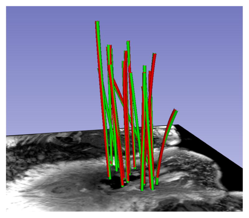
The maximum HD between automatic segmentation of MR images and “ground truth”, as determined from manual segmentation of CT images for the 12 catheters was 3.5 mm. The mean HD was 2.3 mm and σ was 0.5 mm. A visual illustration is provided in Figure 3. The RMS error of catheter tip locations from the registration of MR and CT images was 1 mm. Rigid registration was performed using markers embedded in the phantom. We assume that the remainder 1 mm error was due to the geometry differences between MR and CT.
Fig. 3.
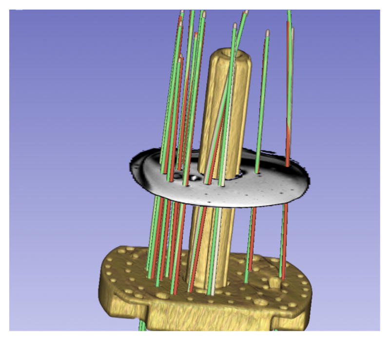
Phantom MRI/CT. HD differences between manual MRI (green) & automatic CT segmentation (red): 3.5 mm (max), 2.3 mm(μ), 0.25 mm2(σ2).
Patient MRI Results
The HD between manual and automatic segmentations was computed on 101 catheters from 10 patients. The catheter tips provided in manual segmentations were used to initialize the automatic segmentation, and an axial plane was defined to mark the proximal end of the catheters. A catheter segmentation was classified as correct if this HD was less than 2 mm. 2 mm was chosen as the classification target by rounding up the 1.6 mm catheter diameter; in the absence of apriori knowledge of the orientation of the device relative to the magnetic field or the imaging planes, the susceptibility artifact is always somewhat greater than the physical device dimensions. The method correctly localized 93 out of 101 catheters in an average time of 0.3 seconds per catheter on a 3GHz Intel Core i7 computer with 16 GB RAM and running Mac OS X 10.7. Figures 4 and 5 illustrate two cases in which all catheters were correctly identified. Table 1 summarizes validation statistics for each of the 10 cases.
Fig. 4.
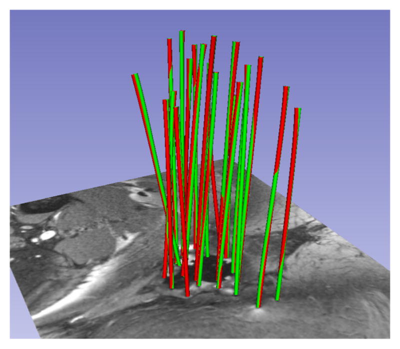
Patient MRI. HD differences between manual (green) and automatic (red) segmentation: 1.23 mm (max), 1.01 mm(μ), 0.01 mm2(σ2).
Fig. 5.
Another patient MRI. HD differences between manual (green) and automatic (red) segmentation: 1.36 mm (max), 1.01 mm(μ), 0.01 mm2(σ2).
Table 1.
Summary of Patient MRI validation. Each row corresponds to a patient; it shows the catheter count, the max, the mean, and the variance of HD across all catheters, the count of catheters that were incorrectly segmented, and statistics on HD (HD*) after the outlier catheters are removed.
| Case ID | Catheter count | MaxHD mm | MeanHD mm | VarHD mm2 | Outliers count | MaxHD* mm | MeanHD* mm | VarHD*mm2 |
|---|---|---|---|---|---|---|---|---|
| 1 | 7 | 1.08 | 0.99 | 0.00 | 0 | 1.08 | 0.99 | 0.00 |
| 2 | 14 | 6.50 | 1.81 | 2.91 | 2 | 1.56 | 1.15 | 0.04 |
| 3 | 8 | 8.93 | 2.74 | 9.53 | 2 | 1.00 | 0.93 | 0.01 |
| 4 | 15 | 1.00 | 0.96 | 0.00 | 0 | 1.00 | 0.96 | 0.00 |
| 5 | 16 | 10.43 | 2.19 | 10.33 | 2 | 1.23 | 1.01 | 0.00 |
| 6 | 5 | 1.00 | 0.97 | 0.00 | 0 | 1.00 | 0.97 | 0.00 |
| 7 | 7 | 1.20 | 1.06 | 0.01 | 0 | 1.20 | 1.06 | 0.01 |
| 8 | 6 | 1.92 | 1.33 | 0.19 | 0 | 1.92 | 1.33 | 0.19 |
| 9 | 9 | 1.22 | 1.05 | 0.01 | 0 | 1.22 | 1.05 | 0.01 |
| 10 | 14 | 17.56 | 3.28 | 29.03 | 2 | 1.67 | 1.19 | 0.09 |
4 Conclusions
This study validated the segmentation of interstitial catheters from MRI images based on a novel method, and demonstrated that this method was able to properly identify most of the catheter positions in clinically reasonable processing times.
5 Discussion and Future Work
Dependence on Tip Initialization
A common failure mode was observed in patient segmentations, especially when a large number of catheters were used. When the user provided a tip position, which was not located sufficiently close to the shaft of the desired catheter, the results varied based on the configuration of neighbouring catheters. Figure 6 illustrates a case where the user-provided tip resulted in a segmentation (red) that terminated in a neighbouring valley of the objective function (i.e. it mistakenly followed the path of a neighboring catheter), while the correct manual segmentation of the catheter is shown in green. In Figure 7, the catheter tip was initialized correctly, and the segmentation (red) closely matched the (green) manual segmentation. To address this weakness in the method, randomly perturbed restarts will be investigated. In addition, we believe that we can explicitly model the relation between the geometry of the catheter tip artifact and its orientation in the static magnetic field, and plan to investigate this for automatic tip detection.
Fig. 6.
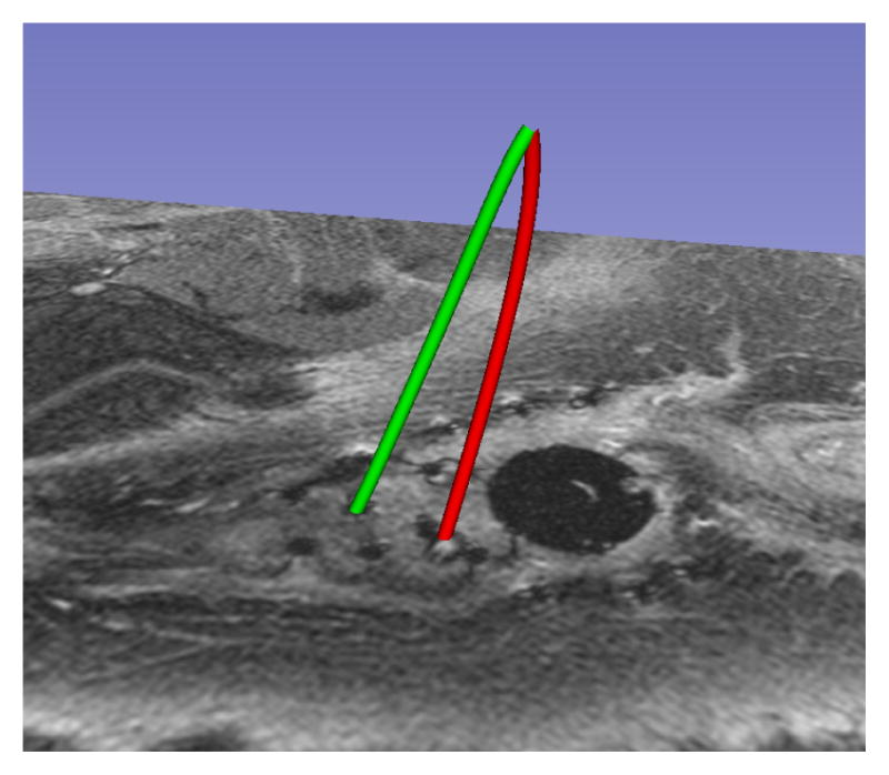
Failure Mode
Fig. 7.
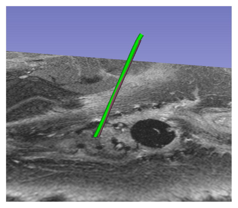
Reinitialized Tip
From Segmentation to Patient Impact
It should be noted that the correlation of segmentation error with radiation dose for our patient cohort is at this time unknown, and will be analyzed in the future. Given the uncertainties associated with dose metrics in brachytherapy, it is unlikely that dose difference due to segmentation errors lower than 2 mm will have a clinical impact. However, neither the dosimetry literature nor published guidelines currently provide tolerances for catheter segmentation error. In order to gauge the benefits of this study to clinical practice, a comparison is needed between radiation plan dose to tumor and organs at risk using the automated catheter segmentation from MR and the standard-of-care catheter segmentation created from CT images. If these two doses turn out to be within the dose uncertainty margins routinely employed in treatment planning, then a contribution will have been made to clinical care; the need of a treatment planning CT will be obviated for cases where appropriate MR imagery is available at the conclusion of the catheter placement procedure. If the MR-based dose turns out to be a significant improvement over CT, then a case will have been made for performing MR based treatment planning instead of CT.
Acknowledgments
This work was supported by NIH Awards R03EB013792, P41EB015898, and U54EB005149. The authors would like to thank Dr. Yi Gao for discussions on segmentation algorithms, Dr. Steve Pieper for guidance in the implementation on the 3D Slicer software platform, and Dr. Ron Kikinis for advice on workflow that has resulted in an application that is easy to use in a clinical setting.
Footnotes
This particular method of choosing λ values delivered the computational efficiency required by the problem but other choices for the series would be valid as well.
References
- 1.Cancer facts & figures. 2012 [ http://www.cancer.org/Research/CancerFactsFigures/CancerFactsFigures/cancer-facts-figures-2012]
- 2.Viswanathan AN, Szymonifka J, Tempany-Afdhal C, Cormack RA. A prospective trial of real-time magnetic resonance-guided catheter placement in interstitial gynecologic brachytherapy. Brachytherapy. doi: 10.1016/j.brachy.2012.08.006. Epub 2013. [DOI] [PubMed] [Google Scholar]
- 3.Poetter R, Haie-Meder C, Van Limbergen E, et al. Recommendations from gynaecological (GYN) GEC ESTRO working group. Radiother Oncol. 2006 Jan;78(1):67–77. doi: 10.1016/j.radonc.2005.11.014. Epub 2006 Jan 5. [DOI] [PubMed] [Google Scholar]
- 4.Cleary K, Peters TM. Image-guided interventions: technology review and clinical applications. Annu Rev Biomed Eng. 2010;12:119–42. doi: 10.1146/annurev-bioeng-070909-105249. [DOI] [PubMed] [Google Scholar]
- 5.Lewin JS. Interventional MR imaging: concepts, systems, and applications in neuroradiology. AJNR Am J Neuroradiol. 1999 May;20(5):735–48. Review. [PMC free article] [PubMed] [Google Scholar]
- 6.Song SE, Cho NB, Iordachita II, Guion P, Fichtinger G, Kaushal A, Camphausen K, Whitcomb LL. Biopsy needle artifact localization in MRI-guided robotic transrectal prostate intervention. IEEE Trans Biomed Eng. 2012 Jul;59(7):1902–11. doi: 10.1109/TBME.2012.2192118. [DOI] [PMC free article] [PubMed] [Google Scholar]
- 7.DiMaio SP, Kacher DF, Ellis RE, Fichtinger G, Hata N, Zientara GP, Panych LP, Kikinis R, Jolesz FA. Catheter Artifact Localization in 3T MR Images. Stud Health Technol Inform. 2006;119:120–5. [PubMed] [Google Scholar]
- 8.Frangi AF, Niessen WJ, Vincken KL, Viergever MA. Medical Image Computing and Computer-Assisted Intervention. MICCAI. Vol. 98. Springer; Berlin Heidelberg: 1998. Multiscale vessel enhancement filtering; pp. 130–137. [Google Scholar]
- 9.Sato Y, Nakajima S, Shiraga N, Atsumi H, Yoshida S, Koller T, Kikinis R. Three-dimensional multi-scale line filter for segmentation and visualization of curvilinear structures in medical images. Medical image analysis. 1998;2(2):143–168. doi: 10.1016/s1361-8415(98)80009-1. [DOI] [PubMed] [Google Scholar]
- 10.Okazawa SH, Ebrahimi R, Chuang J, Rohling RN, Salcudean SE. Methods for segmenting curved catheters in ultrasound images. Med Image Anal. 2006 Jun;10(3):330–42. doi: 10.1016/j.media.2006.01.002. Epub 2006 Mar 7. [DOI] [PubMed] [Google Scholar]
- 11.Huttenlocher DP, Klanderman GA, Rucklidge WJ. Comparing images using the Hausdorff distance. IEEE Transactions on Pattern Analysis and Machine Intelligence. 1993;15(9):850–863. doi: 10.1109/34.232073. [DOI] [Google Scholar]


