

Abstract
Robotic assistants and smart surgical instruments have been developed to overcome many significant physiological limitations faced by vitreoretinal surgeons, one of which is lack of force perception below 7.5 mN. This paper reports the development of a new force sensor based on fiber Bragg grating (FBG) with the ability to sense forces at the tip of the surgical instrument located inside the eye and also provide information about instrument interaction with the sclera. The sclera section provides vital feedback for cooperative robot control to minimize potentially dangerous forces on the eye. Preliminary results with 2×2 degree-of-freedom (DOF) sensor and force scaling robot control demonstrate significant reduction of forces on the sclera. The design and analysis of the sensor is presented along with a simulated robot assisted retinal membrane peeling on a phantom with sclera constraints and audio feedback.
I. Introduction
Vitreoretinal surgery refers to the intraocular surgical procedures that treat retina-related diseases, such as macular degeneration, retina detachment, and diabetic retinopathy. Vitreoretinal surgery is one of the most technically demanding microsurgeries, because it requires fine, precise motion to manipulate delicate tissue in a small and constrained workspace, i.e. the interior of the eye. A typical surgical task is epiretinal membrane (ERM) peeling where the surgeon inserts a small instrument (e.g. 25 Ga) with micro-forceps through a trocar on the sclera, and carefully peels a thin, semi-transparent membrane (the ERM) off the retina, to restore a patient’s vision from ERM distortion. In addition to the above challenges, the surgeon needs to execute this task in absence of force sensing. Gupta et al. [1] studied forces applied during in vitro retinal manipulation in porcine cadaver eyes. About 75% of all forces measured are below 7.5 mN and only 19% of the events with this force magnitude can be felt by the surgeons. Furthermore, the surgical performance is limited by physiological hand tremor, fatigue, poor kinesthetic feedback, and patient movement. Robotic assistance augmented with smart instruments with various sensing modalities could enhance and expand the capabilities of microsurgery, improve safety and efficacy of the surgical procedures, and deliver better surgical outcomes and greater patient satisfaction.
There have been many studies in development of robotic systems for retinal surgery and microsurgery in general. A major approach is a master-slave teleoperated robotic system [2]–[7]. The commercially available da Vinci surgical system has also been experimented with to investigate its feasibility for retinal surgery [8] [9]. Such master-slave configuration can achieve precise manipulation using motion scaling, but often includes disadvantages such as large footprint, complex system design, and high cost. Another approach is actively stabilized handheld instrument called Micron that cancels user hand tremor by actuation of the instrument tip [10]. It provides an intuitive interface with inherent direct 1:1 force feedback to improve the manipulation precision, but as a result, it does not amplify the human-imperceptible forces exerted in vitreoretinal surgery. Our approach is hands-on cooperative control [11]–[14], where the user and the robot both hold the surgical instrument. The force exerted by the user on the handle of the surgical tool guides the robot to comply with the user’s movement. The robot stiffness enables stability to attenuate tremor. This cooperative robotic system combines the precision and sensitivity of a machine, and the manipulative transparency and immediacy of hand-held instruments that the surgeon uses comfortably every day. This robot paradigm can also incorporate additional tool mounted sensors to enhance user perception of the environment.
One of these is force sensing to restore or render safety-critical manipulation force, which is often well below human sensory threshold [1]. Various investigations have been carried out to develop force sensors for microsurgery, micromanipulation and minimally invasive surgery [15]–[18]. A handle mounted force sensor [19] is not practical for vitreoretinal surgery because it cannot distinguish the force applied at the instrument tip and the contact force with the sclera. In order to directly measure the tool-to-tissue interaction force, we have developed a family of force sensing instruments incorporating fiber optic sensors into the distal portion of the instrument shaft that is typically located inside the eye [20]–[22]. Previous studies have demonstrated that auditory [24] [25] and haptic feedback [25] based on force sensing can effectively improve the consistency of the applied forces and regulate the applied forces under a desired threshold.
One observation from using the cooperatively controlled Steady-Hand Eye Robot [13][14] in in vivo experiments is that the robot stiffness does not just prevent hand tremor to provide steady motion, but also reduces the user perceived level of the forces exerted between the instrument shaft and the sclera. Although the sclera can tolerate greater forces than the retina does, excessive forces on the sclera can also cause serious complications, mainly from the physiological limits of eye motion, and the eye socket geometry. In robot assisted eye surgery there exist a number of scenarios where this is an issue: in View Adjustment where the surgeon torques the eye with currently inserted instruments to achieve desired view of the retina; deliberate Deformation of the eye to provide access to peripheral areas of the retina; and Patient Motion causing uncontrolled translation of the eye. Furthermore imprecise Tool Coordination between the left and the right instruments can cause dangerously large tension on the sclera. For example, in View Adjustment the surgeon often needs to move the patient’s eye with two instruments (e.g. a light pipe and a micro-forceps), while simultaneously minimizing their effect on the sclera. This is especially pertinent in Bimanual Robot Assistance, see Fig. 1(a), where the robots have limited information about the location of the eye and even diligent user can inadvertently violate the two sclera entry point constraint, as shown in Fig. 1(b) and (c).
Figure 1.

Left and Right Eye Robots arranged for bimanual operation on skull phantom (a). Close-up of surgeon controlling the robots with instruments inserted into the eye through sclera trocars (b). Arrow depicts the constant geometric separation of the trocars required for safe surgery (c).
In practice, surgeons strive to minimize the sclera forces by actively constraining the instrument motion to only three rotations about the sclera entry point and one translation along the instrument axis. Therefore the patient’s eye is negligibly translated or rotated, and only minimal axial friction and transverse forces are exerted at the sclera entry point. In robotics, this corresponds to the concept of remote center-of-motion (RCM) devised by Taylor et al. [26]. This approach only addresses a few of the scenarios prompting us to devise a novel dual force sensing instrument that can measure forces at the instrument tip as well as forces at the sclera entry point. These force measurements are incorporated into the cooperative control algorithm to provide auditory and haptic feedback. A phantom was developed for a planar membrane peeling task with a simulated sclera constraint that approximates the sclera stiffness. In this paper we investigate the effectiveness of force feedback and compare with previous control methods as well as with a freehand approach. The preliminary results demonstrate that the new dual force sensing instrument with different force feedback methods can further improve the performance of the cooperative robotic assistant for vitreoretinal surgery.
II. Dual Force Sensing Instrument
A. Design
The conceptual design of the dual force sensing instrument follows our previous force sensing instruments [20]–[22]. To achieve a good balance between miniature instrument size and sensing performance, we decided to incorporate fiber Bragg grating (FBG) sensors to manufacture the dual force sensing instrument, due to its small size, good sensitivity, low cost, sterilizability, biocompatibility, and immunity from electrostatic and electromagnetic noises.
The instrument shaft is a titanium wire with 0.5 mm diameter, which is the same as the 25 Ga ophthalmic instruments. To integrate the FBG sensors, three square section channels (0.16 × 0.16 mm) are longitudinally machined into the instrument shaft, as shown in Fig. 2(b). The new dual force sensing instrument consists of two force sensing segments along the tool shaft. Each sensing segment can measure transverse forces that are perpendicular to the instrument axis. For a proof of concept, the axial force components are not considered for this first prototype, but will be included in the next iteration. Each FBG sensor (Technica S.A., Beijing, China) has two FBG segments with lengths of 5 mm, one (tip FBG) is located at 5 mm from the instrument tip with center Bragg wavelength of 1535 nm, while the other (sclera FBG) is located 32 mm from the instrument tip with center Bragg wavelength of 1555 nm, as shown in Fig. 2(a). The tip FBG typically remains inside the eye, so that it measures the tool-to-tissue interaction forces without distortion from the contact with the sclera. The sclera FBG sensor is always located outside the eye because its distance to the instrument tip (32 mm) is greater than the average diameter of human eye (25 mm). The total instrument shaft length is 40 mm, see Fig. 2(c). The sm 130-700 optical sensing interrogator from Micron Optics (Atlanta, GA) is used to monitor the FBG sensors within the spectrum from 1525 nm to 1565 nm at a 2 kHz refresh rate.
Figure 2.

Dimension of the dual force sensing instrument (a). The cross-section view of the instrument shaft (b). Photo of the dualforce sensing instrument (c). All dimensions are in mm.
B. Force Calculation
The force calculation algorithm derives from that presented by Iordachita et al. [20]. The strain is proportional to the moment and thus proportional to the force applied:
| (1) |
where ε is the local strain at the sclera FBG sensors, M is the moment exerted at the FBG sensors, is the force applied, F is the distance between the force and the FBG sensor, F is the Young’s modulus, I is the moment of inertia, and r is the distance between neutral axis and the FBG sensor.
The shift in Bragg wavelength of the FBG sensors is proportional to local strain and temperature change:
| (2) |
where Δλ denotes the shift in Bragg wavelength, ε denotes the local strain, ΔT denotes the temperature change, kε and kΔT are constant coefficients.
By subtracting the mean value of the three FBG sensors at each sensing segment, the common mode caused by the axial strain and temperature change is removed. We call the remaining differential mode sensor reading Δsi:
| (3) |
where Δsi denotes the differential mode in FBG sensor i, Δλi denotes the shift in Bragg wavelength of FBG sensor i, kεi is the strain coefficient of FBG sensor i, εi is the local strain of FBG sensor i, and i = 1, 2, and 3.
We can show there is a linear relationship between sensor reading and the forces applied. The tip FBG sensors only measure the instrument tip forces, thus:
| (4) |
where ΔSt = [Δst1, Δst2, Δst3]T denotes the sensor reading in the tip FBG sensors, Ft = [Ftx, Ftx]T denotes the transverse forces exerted at the instrument tip, and Ktt is a 3×2 coefficient matrix representing the linear mapping from tip forces to tip FBG sensor readings.
The sclera FBG sensors respond to both tip forces and sclera forces, therefore:
| (5) |
where ΔSs = [Δss1, Δss2, Δss3]T denotes the sensor reading in the sclera FBG sensors, Fs = [Fsx, Fsy]T denotes the transverse forces exerted between the instrument shaft and the sclera, Ft = [Ftx, Ftx]T denotes the transverse forces exerted at the instrument tip, Kss and Kst are both 3×2 coefficient matrices that represent the linear mapping from sclera forces to sclera FBG sensor readings and that from tip forces to sclera FBG sensor reading respectively.
The coefficient matrices Ktt, Kss, and Kst can be obtained through calibration by applying known forces at the instrument tip and at the sclera entry point separately.
The tip forces can then be calculated as follows:
| (6) |
where Ktt+ is the pseudo-inverse of Ktt.
To calculate the sclera forces, we only need the portion in the sclera FBG sensor reading that only result from the sclera forces. Tip force portion resulted in sclera FBG sensor readings is subtracted:
| (7) |
where Kss+ is the pseudo-inverse of Ktt.
C. Discussion on Sclera Force Measurement
It is important to note that while the tool-to-tissue interaction forces are consistently applied at the instrument tip, the location of the forces generated by the tool contacting the sclera can vary along the instrument shaft according to the instrument length inserted inside the eye. If this contact point is not defined, the sclera force sensor cannot provide exact measurement of the actual force magnitude applied to the sclera. Instead, it measures the resulting moment from the sclera forces at the location where the sensor is calibrated.
However, this is consistent with how the surgeon perceives the sclera force with a handheld instrument — only perceiving the resulted moment at the instrument handle, not the actual forces exerted at the sclera. In addition, the instrument length inside the eye only varies in a small range when the surgeon performs a surgical task at the back of the eye, e.g. a roughly 13 mm arced path of the tip along the surface of the retina, produces about 1mm axial tool translation. Calibration at maximum possible instrument insertion length (25 mm from the instrument tip) provides a sufficiently accurate sclera force measurement when the instrument tip is close to the furthest point on the retina from the trocar, and a conservative estimation when the instrument is not fully inserted, i.e. the moment arm is longer than that in the calibration.
III. Force Feedback with Cooperative Robotic Assistant
We then integrate the dual force sensing into the cooperative control algorithm of the Steady-Hand Eye Robot. The proposed force feedback method is to employ auditory feedback for instrument tip forces and haptic feedback for sclera forces. Because the surgeon can feel the sclera forces with a handheld instrument in freehand mode, haptic feedback for the sclera forces in the robotic setup may provide the surgeon with more intuitive perception of the sclera forces.
A. Force-To-Auditory Sensory Substitution
The auditory feedback scheme presented by Balicki et al. [25] is employed to reflect the instrument tip forces. It modulates playback tempo of audio “beeps” in four force level zones. The audio is silent for forces smaller than 1 mN in magnitude. A constant slow beeping indicates a “safe zone” with forces from 1 to 3.5 mN. Then follows a “cautious zone” with proportionally increasing tempo to modulate forces from 3.5 to 7 mN. Lastly, a “danger zone” generates a constant fast beeping for all forces greater than 7 mN.
B. Force Scaling
We use force scaling [25] [27] to provide haptic feedback for the sclera forces, such that the user can feel the sclera forces in a similar way in which she would with a handheld instrument in freehand mode. The previous robot proportional velocity control is:
| (8) |
where ẋ is robot handle velocity in Cartesian space, Fh denotes user’s force input at the handle, and α is a constant gain.
To incorporate the sclera forces, we can modify the cooperative control law:
| (9) |
where γ is a force scaling factor, and is the sclera force resolved at the instrument handle with the following adjoint transformation [28]:
| (10) |
where with R as the rotation and p as the translation component of the transformation from local instrument frame at the sclera to the robot handle Cartesian frame.
IV. Experiments and Results
A. Calibration of the Dual Force Sensing Instrument
The basic calibration procedure follows [20]: Shift in Bragg wavelength of each FBG sensor is measured while known transverse force load is applied to the instrument. The calibration is carried out in two stages. First, a transverse force up to 20 mN is applied only at the instrument tip; second, a transverse force up to 100 mN is applied only at 25 mm from the instrument tip, approximately the sclera location when the instrument is tip is placed close to the retina.
Fig. 3 illustrates the sensor reading of both tip and sclera FBG sensors vs. force applied at the instrument tip. All FBG sensors exhibit a good linear response. The sclera FBG sensors generate larger shifts in Bragg wavelength because they are located further away from where the forces are applied. The following coefficient matrices are obtained from the first calibration stage:
| (11) |
| (12) |
Figure 3.

Calibration results with forces only applied at the instrument tip.
Figure 4 illustrates the calibration results from the second calibration stage, where the force load is applied at 25 mm from the instrument tip. Since the tip FBG sensors are not loaded, only sensing noise (±1 pm) is recorded. The sclera FBG sensors also demonstrate linear response to the force load. The third coefficient matrix is obtained from the second calibration stage:
| (13) |
Figure 4.

Calibration results with forces only applied at 25mm from the instrument tip.
B. Membrane Peeling Experiment with Force Feedback
1) Phantom and Experiment Setup
To study the effectiveness of the proposed force feedback method, we designed a phantom to enable a planar membrane peeling task with a simulated sclera constraint. Balicki et al. [25] found that sticky tabs from 19 mm Clear Bandages (RiteAid brand) can provide similar delaminating forces as the retinal tissue manipulation forces with good repeatability. The tab is sliced into 2 mm wide strips and adhered to an acrylic plate using double-side tape. The strips are marked with red line at 10 mm to indicate the maximum peeling length which corresponds to 20 mm of instrument tip travel. An acrylic fixture with a height of 25 mm and a width of 50 mm is built to tension a rubber band to simulate one-sided sclera constraint, as shown in Fig. 5 (c). We tested different rubber bands with our surgeon co-authors and selected the one with the stiffness that is considered closest to that of the sclera manipulation. The acrylic plate with the strips can slide on the base plate of the rubber band fixture, and its position can be locked with two set screws. This enables variation of the relative position between the strips and the rubber band.
Figure 5.
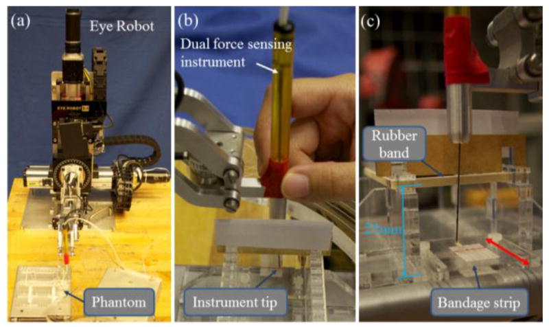
Experiment steup with the Eye Robot and phantom (a). The view of the subject during the experiment. Visibility of the rubber band is obstructed (b). Close-up of the phantom. Red arrow shows that the position of the acrylic plate with the bandage strips can be changed (c).
In the experiment, we want to allow the subject to concentrate on the membrane peeling task, and test the effectiveness of reducing sclera forces. To reduce experiment control factors, the task is reduced to a planar motion. The subject is asked to hold the dual force sensing instrument perpendicular to the membrane plane and peel off the membrane under the aid of auditory feedback based on the tip forces. As shown in Fig. 5 (b), the visibility of the sclera is obstructed such that the subject can only see the instrument tip and the membrane, similar to the surgeon’s view in the microscope. The subject must continue peeling until she feels that the instrument comes into contact with the sclera, and then stop the peeling to avoid damaging the sclera. The relative position between the strip plate and the rubber band is varied between trials to prevent the subject from memorizing the location of the rubber band.
We compared freehand, robot assistance without force scaling, and robot assistance with force scaling based on sclera forces. For each condition, the subject performs 10 practice trials, followed by 10 actual trials.
2) Results
Consistent with previous studies, the auditory feedback regulates the instrument tip force under the desired threshold for all conditions. We are more interested in the sclera forces exerted under different conditions. The maximum sclera forces the subject reaches before stop are summarized in Table I. While freehand trials show the sclera force level that is perceivable to the human user, robot assistance with force scaling results in significantly lower sclera forces during the membrane peeling task. Robot assistance without force scaling agrees with our experience of using the robot with the previous cooperative control method in the in-vivo experiments. Lack of perception of sclera forces yields excessive tension to the sclera. Fig. 6 illustrates example sclera force traces from each condition.
TABLE I.
Membrane Peeling Experiment Results
| Method | Max. force applied on the “sclera” before stop | |||
|---|---|---|---|---|
| Mean | Min | Max | Std. | |
| Freehand | 34.81 mN | 14.87 mN | 67.78 mN | 16.50 mN |
| Robot w/o FS | 215.33 mN | 133.19 mN | 271.57 mN | 43.15 mN |
| Robot with FS | 6.59 mN | 4.97 mN | 12.27 mN | 2.31 mN |
Figure 6.

Exmaple sclera force traces from freehand (top), robot without force scaling (middle), and robot with force scaling (bottom)
V. Discussion and Conclusion
In this paper, we present a novel dual force sensing instrument for vitreoretinal surgery that can measure tool-to-tissue forces at the instrument tip and interaction forces at the sclera entry point. The calibration shows that the force sensors exhibit good linearity and can measure transverse forces robustly against temperature. Using this sensor in conjunction with robotic assistance to provide otherwise human-imperceptible retinal manipulation forces has been shown as an effective way to assist in delicate retinal manipulation tasks. By integrating an additional micro-force sensor into the shaft of the surgical tool, we can further enhance the transparency of the robotic assistance by communicating sclera interaction information through force scaling. This minimizes surgical risks associated with excessive application of forces during manipulation of the eye.
The current embodiment of the concept does not measure axial forces for either sensor – this requires impractical motion of the tool such that only transverse forces are applied. This will be addressed in the next generation of instruments with 3-DOF force sensing capability. Furthermore, multiple FBG sensors can also be utilized for shape and deflection estimation of the instrument shaft [29], which can in turn be used to calculate the transformation from robot tool handle to the instrument tip.
The dual force sensing system can be applied in many surgical disciplines, for example in otology, to minimize contact forces in the ear canal during cochlear implant electrode insertion. It can also be employed in surgical training. For instance, auditory and/or force feedback can help the junior surgeons to be more aware of the instrument tip force and sclera force to improve surgical techniques.
Acknowledgments
Research supported in part by NIH BRP grant 1 R01 EB 007969, in part by Wilmer Eye Institute’s Research to Prevent Blindness, and in part by Johns Hopkins University internal funds. Other equipment and systems infrastructure support were developed within the CISST ERC under NSF grant EEC9731748.
Contributor Information
Xingchi He, Email: xingchi.he@jhu.edu, Mechanical Engineering Department, Johns Hopkins University, Baltimore, MD 21218 USA.
Marcin Balicki, Computer Science Department, Johns Hopkins University, Baltimore, MD 21218 USA.
Peter Gehlbach, Department of Ophthalmology, Johns Hopkins School of Medicine, Baltimore, MD 21287 USA.
James Handa, Computer Science Department, Johns Hopkins University, Baltimore, MD 21218 USA.
Russell Taylor, Computer Science Department, Johns Hopkins University, Baltimore, MD 21218 USA.
Iulian Iordachita, Mechanical Engineering Department, Johns Hopkins University, Baltimore, MD 21218 USA.
References
- 1.Gupta P, Jensen P, de Juan E. Surgical forces and tactile perception during retinal microsurgery. International Conference on Medical Image Computing and Computer Assisted Intervention; 1999. pp. 1218–1225. [Google Scholar]
- 2.Charles S, Das H, Ohm T, Boswell C. Dexterity-enhanced telerobotic microsurgery. IEEE International Conference on Robotics and Automation; 1997. pp. 5–10. [Google Scholar]
- 3.Nakano T, Sugita N, Ueta T, Tamaki Y, Mitsuishi M. A parallel robot to assist vitreoretinal surgery. International Journal of Computer Assisted Radiology and Surgery. 2009 Nov;4(6):517–26. doi: 10.1007/s11548-009-0374-2. [DOI] [PubMed] [Google Scholar]
- 4.Ida Y, Sugita N, Ueta T, Tamaki Y, Tanimoto K, Mitsuishi M. Microsurgical robotic system for vitreoretinal surgery. International Journal of Computer Assisted Radiology and Surgery. 2012 Jan;7(1):27–34. doi: 10.1007/s11548-011-0602-4. [DOI] [PubMed] [Google Scholar]
- 5.Wei W, Goldman R, Simaan N. Design and theoretical evaluation of micro-surgical manipulators for orbital manipulation and intraocular dexterity. IEEE International Conference on Robotics and Automation; April 2007.pp. 10–14. [Google Scholar]
- 6.Meenink HCM, Rosielle RHPCJN, Steinbuch M, Nijmeijer H, de Smet MC. A master-μslave robot for vitreo-retinal eye surgery. The euspen Internationl Conference; June 2010.pp. 3–6. [Google Scholar]
- 7.Bourges JL, Hubschman JP, Wilson J, Prince S, Tsao TC, Schwartz S. Assessment of a hexapod surgical system for robotic micro-macro manipulations in ocular surgery. Ophthalmic Research. 2011 Jan;46(1):25–30. doi: 10.1159/000314719. [DOI] [PubMed] [Google Scholar]
- 8.Tsirbas A, Mango C, Dutson E. Robotic ocular surgery. The British Journal of Ophthalmology. 2007 Jan;91(1):18–21. doi: 10.1136/bjo.2006.096040. [DOI] [PMC free article] [PubMed] [Google Scholar]
- 9.Bourla DH, Hubschman JP, Culjat M, Tsirbas A, Gupta A, Schwartz SD. Feasibility study of intraocular robotic surgery with the da Vinci surgical system. Retina Philadelphia Pa. 2008 Jan;28(1):154–158. doi: 10.1097/IAE.0b013e318068de46. [DOI] [PubMed] [Google Scholar]
- 10.Maclachlan RA, Becker BC, Tabar JC, Podnar GW, Lobes LA, Riviere CN. Micron: an actively stabilized handheld tool for microsurgery. IEEE Transactions on Robotics. 2012;28(1):195–212. doi: 10.1109/TRO.2011.2169634. [DOI] [PMC free article] [PubMed] [Google Scholar]
- 11.Taylor R, Jensen P, Whitcomb L, Barnes A, Stoianovici D, Gupta P, Wang Z, de Juan E, Kavoussi L. A Steady-Hand robotic system for microsurgical augmentation. The International Journal of Robotics Research. 1999;18(12):1201–1210. [Google Scholar]
- 12.Mitchell B, Koo J, Iordachita I, Kazanzides P, Kapoor A, Handa J, Hager G, Taylor R. Development and application of a new steady-hand manipulator for retinal surgery. IEEE International Conference on Robotics and Automation; 2007. pp. 623–629. [Google Scholar]
- 13.Uneri A, Balicki MA, Handa J, Gehlbach P, Taylor RH, Iordachita I. New Steady-Hand Eye Robot with micro-force sensing for vitreoretinal surgery. IEEE International Conference on Biomedical Robotics and Biomechatronics; 2010. pp. 814–819. [DOI] [PMC free article] [PubMed] [Google Scholar]
- 14.He X, Roppenecker D, Gierlach D, Balicki M, Olds K, Gehlbach P, Handa J, Taylor RH, Iordachita I. Toward clinically applicable Steady-Hand Eye Robot for vitreoretinal surgery. ASME Intentional Mechanical Engineering Congress & Exposition; 2012. (accepted) [Google Scholar]
- 15.Menciassi A, Eisinberg A, Scalari G, Anticoli C, Carrozza M, Dario P. Force feedback-based microinstrument for measuring tissue properties and pulse in microsurgery. IEEE International Conference on Robotics and Automation; 2001. pp. 626–631. [Google Scholar]
- 16.Seibold U, Kubler B, Hirzinger G. Prototype of instrument for minimally invasive surgery with 6-axis force sensing capability. IEEE International Conference on Robotics and Automation; April 2005; pp. 496–501. [Google Scholar]
- 17.Peirs J, Clijnen J, Reynaerts D, Van Brussel H, Herijgers P, Corteville B, Boone S. A micro optical force sensor for force feedback during minimally invasive robotic surgery. Sensors and Actuators A: Physical. 2004 Sep;115(2–3):447–455. [Google Scholar]
- 18.Polygerinos P, Ataollahi A, Schaeffter T, Razavi R, Seneviratne LD, Althoefer K. MRI-compatible intensity-modulated force sensor for cardiac catheterization procedures. IEEE Transactions on Bio-Medical Engineering. 2011 Mar;58(3):721–6. doi: 10.1109/TBME.2010.2095853. [DOI] [PubMed] [Google Scholar]
- 19.Berkelman PJ, Whitcomb LL, Taylor RH, Jensen P. A miniature microsurgical instrument tip force sensor for enhanced force feedback during robot-assisted manipulation. IEEE Transactions on Robotics and Automation. 2003;19(5):917–921. [Google Scholar]
- 20.Iordachita I, Sun Z, Balicki M, Kang JU, Phee SJ, Handa J, Gehlbach P, Taylor R. A sub-millimetric, 0.25 mN resolution fully integrated fiber-optic force-sensing tool for retinal microsurgery. International Journal of Computer Assisted Radiology and Surgery. 2009 Jun;4(4):383–390. doi: 10.1007/s11548-009-0301-6. [DOI] [PMC free article] [PubMed] [Google Scholar]
- 21.He X, Balicki M, Kang JU, Gehlbach P, Handa J, Taylor R, Iordachita I. Force sensing micro-forceps with integrated fiber Bragg grating for vitreoretinal surgery. SPIE Phontics West. 2012;8218-82180W:1–7. [Google Scholar]
- 22.Kuru İ, Gonenc B, Balicki M, Handa J, Gehlbach P, Taylor RH, Iordachita I. Force sensing micro-forceps for robot assisted retinal surgery. 34th Annual International Conference of the IEEE Engineering in Medicine and Biology Society (EMBC); 2012. [DOI] [PMC free article] [PubMed] [Google Scholar]
- 23.Liu X, Iordachita I, He X, Taylor R, Kang JU. Miniature fiber-optic force sensor based on low-coherence Fabry-Pérot interferometry for vitreoretinal microsurgery. Biomedical Optics Express. 2012 May;3(5):1062–1076. doi: 10.1364/BOE.3.001062. [DOI] [PMC free article] [PubMed] [Google Scholar]
- 24.Kitagawa M, Dokko D, Okamura AM, Yuh DD. Effect of sensory substitution on suture-manipulation forces for robotic surgical systems. The Journal of Thoracic and Cardiovascular Surgery. 2005 Jan;129(1):151–8. doi: 10.1016/j.jtcvs.2004.05.029. [DOI] [PubMed] [Google Scholar]
- 25.Balicki M, Uneri A, Iordachita I, Handa J, Gehlbach P, Taylor R. Micro-force sensing in robot assisted membrane peeling for vitreoretinal surgery. International Conference on Medical Image Computing and Computer-Assisted Intervention; 2010. pp. 303–310. [DOI] [PMC free article] [PubMed] [Google Scholar]
- 26.Taylor RH, Funda J, Grossman DD, Karidis JP, LaRose DA. Remote center-of-motion robot for surgery. U.S. Patent 5,397,323. 1995 Mar 14;
- 27.Kumar R, Berkelman P, Gupta P, Barnes A, Jensen PS, Whitcomb LL, Taylor RH. Preliminary experiments in cooperative human/robot force control for robot assisted microsurgical manipulation. IEEE International Conference on Robotics and Automation. 2000;1:610–617. [Google Scholar]
- 28.Murray RM, Li Z, Sastry SS. A Mathematical Introduction to Robotic Manipulation. CRC Press; 1994. [Google Scholar]
- 29.Park Y, Elayaperumal S, Daniel B, Ryu SC, Shin M, Savall J, Black RJ, Moslehi B, Cutkosky MR. Real-Time Estimation of 3-D Needle Shape and Deflection for MRI-Guided Interventions. IEEE/ASME Transactions on Mechatronics. 2010;15(6):906– 915. doi: 10.1109/TMECH.2010.2080360. [DOI] [PMC free article] [PubMed] [Google Scholar]