Abstract
Core/shell-like nanostructured xLi2MnO3·(1−x)LiMO2 (M = Ni, Co, Mn) composite cathode materials are successfully synthesized through a simple solid-state reaction using a mechanochemical ball-milling process. The LiMO2 core is designed to have a high-content of Ni, which increases the specific capacity. The detrimental surface effects arising from the high Ni-content are countered by the Li2MnO3 shell, which stabilizes the nanoparticles. The electrochemical performances and thermal stabilities of the synthesized nanocomposites are compared with those of bare LiMO2. In particular, the results of time-resolved X-ray diffraction (TR-XRD) analyses of xLi2MnO3·(1−x)LiMO2 nanocomposites as well as their differential scanning calorimetry (DSC) profiles demonstrate that the Li2MnO3 shell is effective in stabilizing the LiMO2 core at high temperatures, making the nanocomposites highly suitable from a safety viewpoint.
As the application of lithium-ion batteries continues to expand to higher energy consumption devices, such as electric vehicles (EVs) and electrical energy storage (EES) systems, the development of higher energy density electrode materials is becoming more essential. For cathodes, materials with higher operating voltage windows and larger specific capacities are being intensively studied1. As a part of these developments of advanced cathode materials, the layered transition metal oxide, which can accommodate more than one unit of Li per molecule, has been receiving the most attention in recent years2,3,4,5,6.
Many studies have attempted to optimize the xLi2MnO3·(1−x)LiMO2 composite system because its capacity can reach higher than 200 mA h g−1. For these composites, the LiMO2 component is primarily responsible for lithium deintercalation and intercalation at voltages lower than 4.5 V (vs. Li/Li+), and Li2MnO3 acts as the additional capacity reservoir when charging above 4.5 V (vs. Li/Li+)2,3,4,5,6, where the irreversible activation of Li2MnO3 into Li2O and MnO2 occurs during the first charge cycle2,3,4,5,6,7,8. Generally, the synthesis of xLi2MnO3·(1−x)LiMO2 (equivalently Li1+αMO2) or LiMO2 has been performed via co-precipitation or sol-gel methods9,10,11,12,13. However, the mechanical treatment of solids, such as the ball milling method, could offer a rather simple and highly efficient process with lower energy consumption and cost14, to prepare these electrode materials.
Recently, West et al. prepared the Li2MnO3 and LiMO2 components separately and performed the synthesis using a ball-milling-annealing process15. These researchers observed that the synthesized composite material exhibited crystallographic characteristics and electrochemical performances similar to those of layered-layered 0.5Li2MnO3·0.5LiNi0.33Co0.33Mn0.33O2 materials prepared by the conventional co-precipitation process15. This result proved that the Li2MnO3 and LiMO2 components do not need to be connected at the atomic level to achieve anomalously high capacities (i.e., capacities greater than 200 mA h g−1). In our previous studies, we used the mechanochemical process to form alloys among nanoparticles16,17,18,19,20. We have also recently demonstrated that Li2MnO3 and LiMO2 can be closely integrated as a nanocomposite in a controlled mole ratio via a mechanochemical process21,22. To increase the specific capacity of LiMO2 (M = Ni, Co, Mn), a good strategy is to increase its Ni content23,24,25,26. However, the cathode material may experience detrimental effects at the surface because the Ni at the surface of the material can be easily oxidized and destabilize the surface of the electrode, resulting in a poorer cycle life and thermal stability27,28,29,30,31.
Sun et al. developed a cathode material Li[(Ni0.8Co0.1Mn0.1)0.8(Ni0.5Mn0.5)0.2]O2 with a microscale core-shell structure; the LiNi0.8Co0.1Mn0.1O2 core yielded a high capacity, while the Li[Ni0.5Mn0.5]O2 shell provided high thermal stability32. In addition, the material exhibited improved cycling performance, with a capacity retention of 98%33. A similar cathode material with an average composition of Li[Ni0.68Co0.18Mn0.18]O2, fabricated by controlling the volume ratio of the core and shell components, also exhibited superior performance34. The results reported by Sun and co-workers demonstrated that the core-shell structure is suitable for improving the electrochemical performance of microscale cathode materials. Thus, it is reasonable to assume that the core/shell-like structure would also be suitable at the nanoscale. If xLi2MnO3·(1−x)LiMO2 nanocomposites were fabricated with a core/shell-like structure, not only would the stability of the material be high, but it would also exhibit anomalously high capacities.
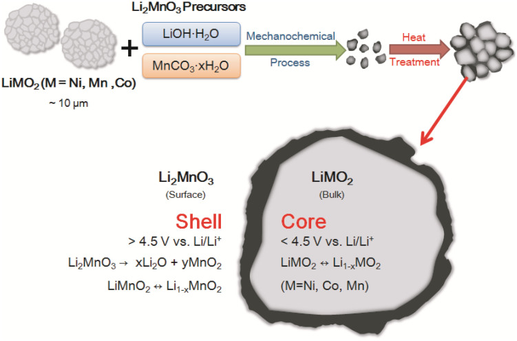
In this study, we synthesized nanoscale core/shell-like structured xLi2MnO3·(1−x)LiMO2 composites for use as cathode materials. The shell was Li2MnO3, while the Ni-rich LiNi0.5Co0.2Mn0.3O2 component formed the core. The nanocomposites were fabricated via a solid-state reaction using a mechanochemical process. The uniform Li2MnO3 coating on the outer surface stabilized the Ni-rich LiMO2 cores, as illustrated in Figure 1. We tested various mole ratios of the two components, Li2MnO3 and LiMO2, to optimize the amount of the surface-coating-forming component (Li2MnO3). We also tested various heat treatment temperatures to investigate whether the temperature had any effect on the structures and electrochemical performances of the nanocomposites. Finally, we investigated whether the thermal stabilities of electrodes formed using the nanocomposite materials were more stable than those of electrodes based on LiMO2 alone.
Figure 1. Schematic of the core/shell-like nanostructure: Li2MnO3 surface coating on LiMO2 (M = Ni, Co, Mn) bulk electrode materials.
Results
Morphologies of the synthesized nanocomposites
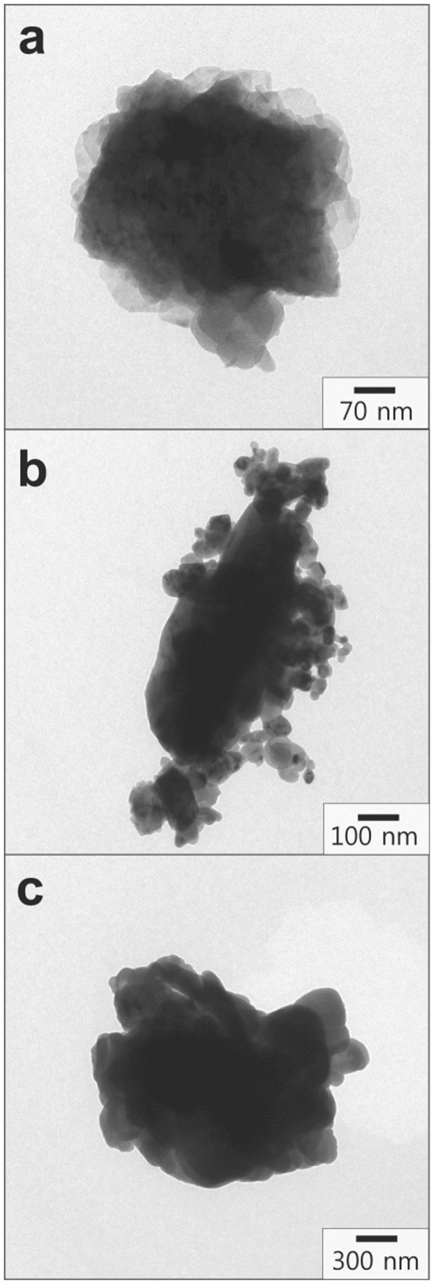
Figure 2 presents the bright field (BF) images of the 0.5Li2MnO3·0.5LiMO2 samples after they had been subjected to heat treatment temperatures at 400, 700, and 1000°C. Note that the scale bars in Figure 2 differ as the particle size of the sample was increased at higher heat treatment temperatures. The particles shown in Figure 2 are primary particles, separated from the secondary particles to obtain the transmission electron microscopy (TEM) images. Based on the TEM image in Figure 2 (a), it can be surmised that nanoscale Li2MnO3 formed at 400°C and completely covered the surface of the LiMO2 particles. Because the particles of the Li2MnO3 sample synthesized at 400°C are much smaller (<50 nm)7 than those of the starting material of LiMO2 (average secondary particle size of ~10 μm before the mechanochemical process), we believe that the Li2MnO3 layer formed on the surfaces of the LiMO2 primary particles after the mechanochemical process and the subsequent heat treatment. With an increase in the heat treatment temperature to 700°C, the particle size of Li2MnO3 increased, as observed in Figure 2 (b)7. The TEM image in Figure 2 (c) also reveals that larger Li2MnO3 particles existed on the surfaces of the LiMO2 particles even after the heat treatment at 1000°C and that the overall particle size increased with the heat treatment temperature. In addition, scanning electron microscopy (SEM) images of xLi2MnO3·(1−x)LiNi0.5Co0.2 Mn0.3O2, where x is 0.3, 0.5, or 0.7, are displayed in Figure S1 (Supplementary Information); the heat treatment temperature was 700°C. Because of the aggregation of the primary nanoparticles, secondary particles formed after the mechanochemical milling process and the subsequent high-temperature heat treatment; this result was consistent with those of our previous studies20,21,22. To confirm whether the surface coating material was Li2MnO3 and the bulk material was LiNi0.5Co0.2Mn0.3O2, we employed energy dispersive X-ray spectroscopy (EDS) to investigate the two materials.
Figure 2. BF images of 0.5Li2MnO3·0.5LiNi0.5Co0.2Mn0.3O2 heat treated at (a) 400°C, (b) 700°C, and (c) 1000°C.
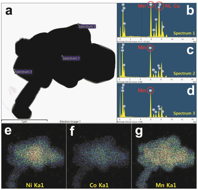
The results of the elemental analysis of the 0.5Li2MnO3·0.5LiMO2 nanocomposite sample prepared at 1000°C are presented in Figures 3 (b), (c), and (d). The elements Ni, Co, and Mn are present at the centers of the particles of the nanocomposite material (see Figure 3 (b)). However, upon observing the surfaces of the particles, it was observed that the element Mn was present on the surfaces in the greatest amount, while Ni and Co were present in much smaller amounts (see Figures 3 (c) and (d)). We believe that this result occurred because during the high-temperature heat treatment at 1000°C, the mixing of the metal cations caused the movement of the transition metals between the Li2MnO3 surface and the LiMO2 bulk; however, the shells of the synthesized electrode materials were designed to be Mn-rich to enhance stabilization.
Figure 3. EDS point elemental analysis and elemental mapping for 0.5Li2MnO3·0.5LiNi0.5Co0.2Mn0.3O2 (1000°C).
(a) electron image, (b) spectrum 1 (bulk), (c) spectrum 2 (surface), (d) spectrum 3 (surface), and elemental maps for (e) Ni, (f) Co, and (g) Mn.
We also performed elemental mapping for the 0.5Li2MnO3·0.5LiMO2 nanocomposite sample prepared at 1000°C; the results are presented in Figs. 3 (e), (f), and (g). The elemental map shows the concentrations of Mn, Co, and Ni. It was evident that Co and Ni were present in smaller amounts at the surface than was Mn. Upon considering the results of the EDS analyses in combination with the elemental concentration maps, it could be surmised that the mechanochemical process was highly effective for synthesizing core/shell-like nanostructures. Furthermore, the nanostructures prepared were such that the Li2MnO3 played the role of stabilizing the LiMO2 core. Finally, to further investigate the crystal structures of Li2MnO3 and LiMO2, high-resolution (HR) TEM was used to image the 0.5Li2MnO3·0.5LiMO2 nanocomposite sample prepared at 1000°C; the image is presented in Figure S2 (Supplementary Information). The fast Fourier transform (FFT) patterns of the images confirmed the existence of both C2/m Li2MnO3 and R-3m LiMO2. This result confirmed that the two components closely integrated with each other at their interfacial region.
Structures of the synthesized nanocomposites
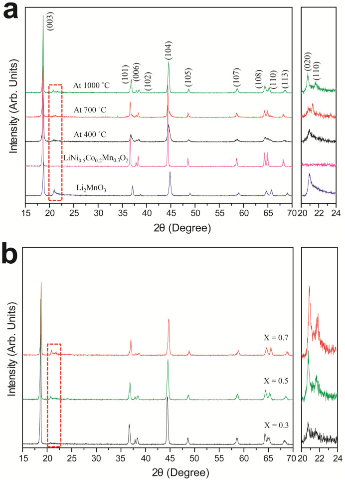
Figure 4 prsents the X-ray diffraction (XRD) profiles of (a) Li2MnO3, (b) LiNi0.5Co0.2Mn0.3O2, and the 0.5Li2MnO3·0.5LiMO2 nanocomposite samples heat treated at (c) 400°C, (d) 700°C, and (e) 1000°C; the values of 2θ range from 15 to 70°. The XRD patterns of all the nanocomposite samples consisted of overlapping peaks of Li2MnO3 and LiMO2. All the diffraction peaks could be indexed as being attributable to a hexagonal structure with the space group R-3m. The image on the right in Figure 4 (a) shows a magnified version of the XRD patterns for 2θ values ranging from 20 to 24°. The low-intensity peaks correspond to the cation ordering in the Li2MnO3 layer2,3,4,5,6,7,8. With increases in the heat treatment temperature, the intensities of these peaks also increased. While the 0.5Li2MnO3·0.5LiMO2 nanocomposite sample heated at 400°C exhibited a single broad peak at 21.1°, a double peak ranging from 21.1 to 21.4° appeared for the sample heated at 700°C. In addition, slight shifts in the peaks at 21.1 and 21.7° were observed for the 0.5Li2MnO3·0.5LiMO2 sample heated at 1000°C. The fact that the (018) and (110) peaks appeared separately, at 64.7 and 65.7°, respectively, suggested that the cation ordering in the nanocomposites was of a high degree and that the nanocomposites exhibited a well-layer structure34,35. Figure 4 (b) presents the XRD patterns of the xLi2MnO3·(1−x)LiMO2 samples (where x is 0.3, 0.5, or 0.7) heat-treated at 1000°C. For these samples, low-intensity peaks also appeared at 21.1 and 21.7°. As a greater amount of Li2MnO3 was incorporated into the nanocomposite, the intensities of the peaks lying between 20° and 24° also increased. The diffraction patterns for the xLi2MnO3·(1−x)LiMO2 samples heat treated at 400 and 700°C are presented in Figures S3 and S4, respectively.
Figure 4.
X-ray diffraction patterns of (a) 0.5Li2MnO3·0.5LiNi0.5Co0.2Mn0.3O2 heat treated at 400, 700, and 1000°C (temperature variation), (b) xLi2MnO3·(1 − x)LiNi0.5Co0.2Mn0.3O2 for x = 0.3, 0.5, or 0.7 and heat treated at 1000°C (mole ratio variation).
To obtain additional structural information on the core-shell nanocomposite, we calculated the lattice parameters based on the space group R-3m, which are summarized in Table S1 (Supplementary Information). When the synthesis temperature was increased, the lattice parameters a and c decreased and increased, respectively, which implies that the overall c/a ratio was increased. This result indicates that the lithium ion can be easily de-/intercalated to the cathode hosts due to the expansion in the z-direction. In addition, we calculated the crystallite size for each sample using the Williamson-Hall method. At each synthesis temperature, as the amount of Li2MnO3 was increased, the overall crystallite size of the nanocomposite samples decreased. This result was consistent with our TEM results in Figure 2 and demonstrated that the particle sizes of the Li2MnO3 on the surface were smaller compared with those of the LiMO2 particles. As the synthesis temperature increased, the crystallite size of our sample also increased7.
Electrochemical measurements and thermal stabilities
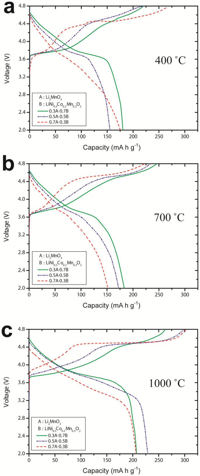
Galvanostatic charge and discharge measurements were performed using cells containing xLi2MnO3·(1−x)LiMO2 as the active material. The 1st cycle charge and discharge profiles for the xLi2MnO3·(1−x)LiMO2 samples (where x = 0.3, 0.5, or 0.7) heat treated at 400°C are shown in Figure 5 (a). The cell containing 0.7Li2MnO3·0.3LiMO2 exhibited a charge capacity of 269.1 mA h g−1; however, this cell also exhibited a large and irreversible capacity loss. The cell containing 0.3Li2MnO3·0.7LiMO2 initially exhibited a lower charge capacity (219.9 mA h g−1) and lower irreversible capacity. Figure 5 (b) shows the 1st cycle charge and discharge profiles for the xLi2MnO3·(1−x)LiMO2 samples heat treated at 700°C. It was observed that the specific capacity decreased as the amount of Li2MnO3 incorporated was increased. Typically, the discharge capacity of Li2MnO3 decreases with an increase in the synthesis temperature because of the resultant increase in the particle size and the decrease in the number of stacking faults in the Li2MnO3 structure7.
Figure 5. 1st cycle charge and discharge curves at 10 mA g−1 (1/20 C) between 2.0 and 4.8 V: (a) 400°C, (b) 700°C, and (c) 1000°C.
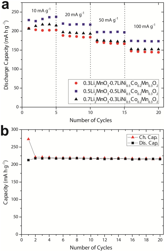
Figure 5 (c) shows the 1st cycle charge and discharge profiles for the xLi2MnO3·(1−x)LiMO2 samples heat treated at 1000°C. The discharge capacities of all the samples were higher, and the samples exhibited significantly smaller losses in their irreversible capacities. The cells containing 0.3Li2MnO3·0.7LiMO2 and 0.7Li2MnO3·0.3LiMO2 exhibited specific capacities of 207.2 and 206.3 mA h g−1, respectively. In addition, the discharge capacity of the cell containing 0.5Li2MnO3·0.5LiMO2 was higher at 228.9 mA h g−1. The 1st and 2nd cycle charge and discharge capacities and efficiencies of the various xLi2MnO3·(1−x)LiMO2 nanocomposite samples, as well as those of Li2MnO3 and LiNi0.5Co0.2Mn0.3O2, are listed in Table S2 (Supplementary Information). The nanocomposite cathode materials prepared at 700 and 1000°C exhibited higher 1st cycle efficiencies than those of Li2MnO3 and LiMO2. After Li2MnO3 activation resulting from charging during the 1st cycle, the nanocomposite samples synthesized at 700 and 1000°C exhibited efficiencies greater than 90% during the 2nd cycle. The rate capabilities of the coin cells containing the xLi2MnO3·(1−x)LiMO2 samples heat treated at 1000°C are plotted in Figure 6 (a); the values correspond to different test current rates. The cell containing 0.3Li2MnO3·0.7LiMO2 exhibited initial discharge capacities as high as 207.2, 188.4, 171.2, and 147.4 mA h g−1 for test current rates of 10 (1/20 C), 20 (1/10 C), 50 (1/5 C), and 100 (1/2 C) mA g−1, respectively. The cell containing 0.7Li2MnO3·0.3LiMO2 exhibited initial discharge capacities of as high as 217.5, 197.1, 175.8, and 152.6 mA h g−1 at current rates of 10, 20, 50, and 100 mA g−1, respectively.
Figure 6. (a) Discharge capacities at different C-rates at 1000°C, (b) cycling performance at 20 mA g−1 (1/10 C) between 2.0 and 4.8 V of the 0.5Li2MnO3·0.5LiNi0.5Co0.2Mn0.3O2 nanocomposite sample heat treated at 1000°C.
Finally, the cell containing 0.5Li2MnO3·0.5LiMO2 exhibited initial discharge capacities as high as 237.5, 219.6, 198.1, and 174.3 mA h g−1 at the current rates of 10, 20, 50, and 100 mA g−1, respectively. Thus, when the Li2MnO3/LiMO2 mole ratio was 0.5:0.5, the nanocomposite sample heat treated at 1000°C exhibited specific capacities higher than those of the other materials. The cycling characteristics of the cell based on the 0.5Li2MnO3·0.5LiMO2 sample heat treated at 1000°C are shown in Figure 6 (b); the values correspond to 20 cycles, initial discharge capacities of 2.0 to 4.8 V, and a current rate of 20 mA g−1 (1/10 C). As mentioned earlier, for the heat treatment temperature of 1000°C, it was expected that the size of the Li2MnO3 particles would increase significantly. In the synthesized core/shell-like nanostructures, Li2MnO3 acts as a coating material. The high-temperature treatment results in the formation of an integrated structure at the interface between the surface layer and the bulk material, which improves the cycling performance. For the sample heat treated at 1000°C, the Li2MnO3 outer layer adheres more strongly to the LiMO2 bulk material and increases the stability of the nanoparticles. Because the specific capacity of Li2MnO3 decreases significantly with the temperature7, it can be concluded that the role played by the Li2MnO3 layer in stabilization is of critical importance. In contrast to the results reported by West et al., who prepared Li2MnO3 and LiMO2 separately using ball-milling and subsequent annealing (the processes had to repeated twice, once for each material), the synthesis technique employed in the current study is simple and robust.
Discussion
In the synthesized nanocomposites, the Li2MnO3 component plays a greater role in stabilization because of the core/shell-like structure. The Li2MnO3 coating, which is present on the outer surfaces of the LiMO2 cores, effectively stabilizes the cores comprising the bulk, resulting in improved electrochemical performances. This result is consistent with those of our previous studies21,22. In addition to the cost of the synthesis technique employed for fabricating the electrode materials, as well as their initial capacities, rate capabilities, and cyclability, the thermal stability of the materials is another important factor for determining their commercial potential.
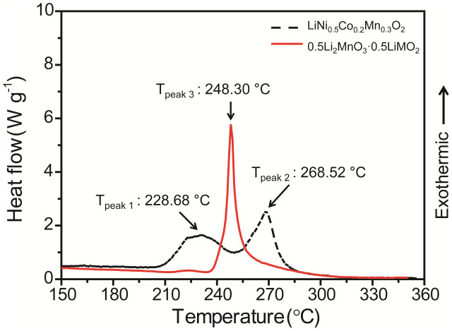
The thermal stabilities of the 0.5Li2MnO3·0.5LiMO2 and LiNi0.5Co0.2Mn0.3O2 nanocomposites after they had been charged to 4.8 V were compared using differential scanning calorimetry (DSC) in a manner similar to that employed by Park et al.36 For 0.5Li2MnO3·0.5LiMO2, the sample heat treated at 1000°C was selected because this sample had exhibited the best electrochemical performance. It can be observed from Figure 7 that the 4.8-V-charged LiNi0.5Co0.2Mn0.3O2 sample, whose particles did not have an outer Li2MnO3 coating, exhibited exothermic peaks corresponding to a two-step dissociation reaction. The temperatures corresponding to the 1st and 2nd exothermic peaks were 228.68 and 268.52°C, respectively; this result indicated that the dissociation of the material occurred through a two-step process36. The total heat generated during the dissociation reaction was 461.5 J g−1. However, only one exothermic peak was observed for the 4.8-V-charged 0.5Li2MnO3·0.5LiMO2 sample, indicating a one-step dissociation reaction. The peak was positioned at 248.30°C, and the total heat generated during the reaction was 239.2 J g−1, which was lower than that for the bare sample. This result is very similar to those reported by other research groups, who have reported that AlF3 or FePO4-coated LiMO2 can stabilize the cathode surface and start to decompose only at high temperatures37,38. Thus, in addition to exhibiting a higher capacity and improved cyclability (see Figs. 5 and 6), the core/shell-like structured 0.5Li2MnO3·0.5LiMO2 sample also exhibited a reduction in the total heat generated and an increase in the dissociation temperature. Therefore, the fact that a greater number of Ni ions were present in the bulk of the electrode resulted in a higher capacity, while the Li2MnO3 shell improved the overall thermal stability of the Li2MnO3-coated materials37. The results of the time-resolved (TR) XRD analyses were in good agreement with the DSC results and provided additional information regarding the changes induced in the various nanocomposite samples after heating. Figures 8 (a) and (b) present the TR-XRD patterns of the LiNi0.5Co0.2Mn0.3O2 and 0.5Li2MnO3·0.5LiMO2 samples heat treated at 1000°C in the absence of an electrolyte; the samples were subsequently heated from room temperature to 600°C and then charged to 4.8 V. The initial TR-XRD data were collected at 38°C because the X-ray generator required more than a few minutes to initialize.
Figure 7. DSC profiles for pristine LiNi0.5Co0.2Mn0.3O2 and the 0.5Li2MnO3·0.5LiNi0.5Co0.2Mn0.3O2 sample heat treated at 1000°C after being charged to 4.8 V vs. Li/Li+.
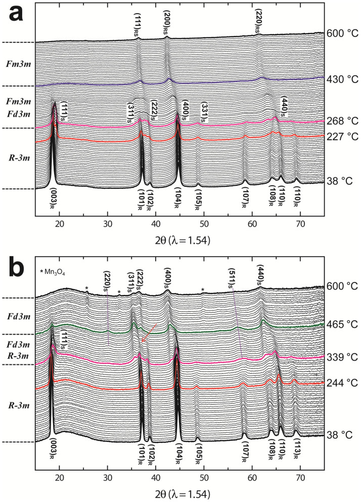
Figure 8. TR-XRD patterns of the (a) LiNi0.5Co0.2Mn0.3O2 and (b) 0.5Li2MnO3·0.5LiNi0.5Co0.2Mn0.3O2 samples heat treated at 1000°C (the temperature was raised to 600°C after being charged to 4.8 V vs. Li/Li+).
We had previously observed that materials with a layered structure undergo phase transformations in the following sequence as the temperature is increased: R-3m → Fd3m → Fm3m. The amount of oxygen released during the phase transformation from Fd3m to Fm3m is higher than that generated during the transformation from R-3m to Fd3m29,30. Thus, it is important to suppress the phase transformation from Fd3m to Fm3m if one wishes to improve the thermal stability of such cathode materials. It can be observed from Figure 8 (a) that, at 38°C, the LiNi0.5Co0.2Mn0.3O2 sample exhibits a structure belonging to the R-3m space group35,39 (i.e., it has a rhombohedral structure). The change in the structure of the sample commences at approximately 227°C; this value agrees well with the DSC data, which is presented in Figure 7 (a). Over the temperature range of 200 to 260°C, which also corresponds to the 1st exothermic peak, the (108) and (110) peaks corresponding to the layered structure merged into a (440) peak, which could be indexed to a disordered spinel structure with the space group Fd3m29,30,31,40. This result indicated that cation mixing increased over this temperature range40. With respect to the 2nd exothermic peak (corresponding to a temperature range extending from approximately 240 to 300°C), the TR-XRD data suggested that the nanocomposite material underwent a phase transformation, with its structure changing from that corresponding to a disordered spinel to that of a rock salt. The (400) and (440) peaks corresponding to the disordered spinel structure disappeared and new (200) and (220) peaks appeared, which could be indexed to the rock salt structure (space group: Fm3m). This rock salt structure was preserved at temperatures as high as 600°C. As observed in Figure 8 (b), the 0.5Li2MnO3·0.5LiMO2 sample exhibited a higher thermal stability than that of the LiNi0.5Co0.2Mn0.3O2 sample.
At 38°C, the 0.5Li2MnO3·0.5LiMO2 sample was observed as having the same structure (i.e., one corresponding to the R-3m space group) as the LiNi0.5Co0.2Mn0.3O2 sample. However, its structure started to change at approximately 244°C, a temperature much higher than that for the LiNi0.5Co0.2Mn0.3O2 sample (~227°C). This value agreed well with the DSC data, which is presented in Figure 7 (b). Further, this temperature is higher than all the previously reported values, which are 223°C for Li0.33Ni0.5Co0.2Mn0.3O240 and 236°C for Li0.33Ni1/3Co1/3Mn1/3O241. It was evident that the layered structure dissociated based on the gradual decrease in the intensities of the (105), (107), and (113) peaks starting at approximately 244°C. The appearance of the (311), (400), and (440) peaks confirmed the formation of a new phase starting at 339°C. The formation of this new phase occurred over the range of 339 to 465°C and was accompanied by the appearance of peaks corresponding to the LiM2O4-type spinel structure. Over the temperature range of 339 to 465°C, in addition to the peaks corresponding to the LiM2O4-type spinel structure, (102), (104), and (110) peaks corresponding to the layered structure were also observed. That is, the layered structure and the spinel structure coexisted over this temperature range. These results indicate that the core/shell-like structure of the nanocomposite 0.5Li2MnO3·0.5LiMO2 not only retarded the transformation of its structure to the spinel structure at high temperatures but also slowed down its dissociation, increasing its thermal stability. However, in contrast to the observations for LiNi0.5Co0.2Mn0.3O2, for 0.5Li2MnO3·0.5LiMO2, another change in structure, that into a Mn3O4-type spinel structure, was also observed. At approximately 490°C, peaks attributed to Mn3O4 began to appear (these peaks are marked with an asterisk). It is highly likely that this Mn3O4-like phase was formed by the dissociation of the Li2MnO3 shells. At the end of the heating stage, that is, at 600°C, 0.5Li2MnO3·0.5LiMO2 exhibited a higher thermal stability than LiNi0.5Co0.2Mn0.3O2.
To conclude, we mechanochemically synthesized xLi2MnO3·(1−x)LiMO2 cathode materials with a core/shell-like nanostructure using a simple solid-state reaction. The synthesis process employed is an easy, one-step, and low-cost method and results in significant improvements in the electrochemical performance of the LiMO2 component due to the presence of the stabilizing Li2MnO3 shell-like layer on the surfaces of the LiMO2 particles. The presence of this Li2MnO3 layer was confirmed using TEM, energy-dispersive spectrometry, and elemental mapping. Furthermore, the presence of Li2MnO3 and LiMO2 on the surfaces and in the bulk, respectively, was also confirmed based on the FFT patterns of the high-resolution transmission electron microscopy (HRTEM) images of the synthesized samples. Of the various samples synthesized, the 0.5Li2MnO3·0.5LiNi0.5Co0.2Mn0.3O2 sample synthesized through a heat treatment at 1000°C exhibited the highest discharge capacity as well as the highest cyclability. The results of the TR-XRD and DSC analyses showed that the synthesized nanocomposite materials exhibited higher thermal stabilities. We propose that the Li2MnO3 coating on the surfaces of the LiMO2 particles effectively stabilized the electrodes consisting of the Ni-rich bulk material.
Methods
Material synthesis
Stoichiometric amounts of LiOH·H2O (≥98%, Aldrich) and MnCO3·xH2O (≥98%, Aldrich) were used to form the Li2MnO3 shells. The precursors were mixed with LiNi0.5Co0.2Mn0.3O2 (~10 μm, L&F Materials Co., Ltd., Korea) using a planetary mill (Pulverisette 5, Fritsch) in the presence of acetone at 350 rpm for 3 h; the ball-to-powder weight ratio was 20:116,17,18,19,20,21,22. Li2MnO3-stablized LiMO2 core/shell-like nanocomposite materials with compositional ratios of 0.3Li2MnO3·0.7LiMO2, 0.5Li2MnO3·0.5LiMO2, and 0.7Li2MnO3·0.3LiMO2 were prepared in this study. The heat treatment was performed at 400, 700, or 1000°C in a box furnace; the heating time was 32 h for the treatment at 400°C and 10 h for the treatments at 700 and 1000°C.
Material characterization
FESEM (NOVA NanoSEM200, FEI) was used to characterize the morphologies of the prepared materials. Enhanced images were obtained using TEM (CM30, Philips). A TEM system (JEM2100F, JEOL) with an EDS attachment and elemental mapping functionality (Inca Energy, Oxford) was used to investigate the elements present on the surfaces and in the bulk of the synthesized cathode materials. HRTEM (Tecnai G2, FEI) was used to investigate the crystal structures of the materials based on their FFT patterns. XRD measurements were performed with a Rigaku X-ray diffractometer using monochromatic Cu-Kα radiation (40 kV and 100 mA). A scan rate of 3° min−1 was selected to collect the diffraction data over 2θ values ranging from 15 to 70°.
Electrochemical measurements
For the electrochemical measurements, coin cells with the CR2032 configuration (Hoshen Corp., Japan) were used. The cells were assembled in a dry room using Li metal for the counter and reference electrodes; Celgard® 2400 was used as the separator. The cathode consisted of a mixture of the synthesized nanocomposite samples, Denka Black®, and polyvinylidene fluoride (PVDF) in 1-methyl-2-pyrrolidone at a weight ratio of 80:10:10. The electrolyte used was a 1 M solution of LiPF6 in an EC:DMC:DEC mixture (1:1:1 by volume). The cells were stored for 24 h before being subjected to galvanostatic charge-discharge cycling tests. We used a multichannel battery tester (Model 4000, Maccor Inc.) in the constant current/constant voltage (CCCV) mode over potentials ranging from 2.0 to 4.8 V; the test current rate was 10 mA g−1 (1/20 C) unless noted otherwise.
Thermal stability analyses
To determine the thermal stabilities of the charged 0.5Li2MnO3·0.5LiMO2 (1000°C) electrodes, TR-XRD and DSC analyses were employed. The TR-XRD analyses were performed using an X-ray diffractometry system (R-AXIS IV++, Rigaku) at the Korea Institute of Science and Technology (KIST) and at the 1D beamline at Pohang Light Source. Before the analyses, the electrodes were charged fully to 4.8 V. Then, the surfaces of the electrodes were scratched. The obtained powder samples were sealed completely and were mounted on the thermal stage of the TR-XRD system. Mo-Kα radiation with a wavelength of 0.7107 Å was used for the X-ray diffractometry system at KIST. To allow for a ready comparison of the obtained results with those reported in the literature, the 2θ values over which the analyses were performed have been converted into values corresponding to Cu-Kα radiation (λ = 1.54 Å). Using the DSC system (Auto Q20, TA Instruments), the thermal stabilities of the electrode materials 0.5Li2MnO3·0.5LiMO2 (1000°C) and LiNi0.5Co0.2Mn0.3O2 were then analyzed, and the capillaries were heated to 600°C at a heating rate of 3°C min−1.
Author Contributions
J.K.N., S.K., D.B., B.W.C. and K.Y.C. conceived, planed and designed the experiments. J.K.N. and S.K. synthesized the cathode materials and performed TEM, SEM, DSC and electrochemical tests. H.K. performed XRD analysis. W. Chang and W. Choi contributed to discussion TEM and DSC results. J.K.N., S.K. and K.Y.C. wrote the main manuscript. B.W.C. and K.Y.C. supervised the whole processes. All authors reviewed the manuscript.
Supplementary Material
Supplementary Information
Acknowledgments
This work was supported by the National Research Foundation of Korea Grant funded by the Korean Government (MEST) (NRF-2011-C1AAA001-0030538). This work was also supported by the KIST Institutional Program (Project No. 2E24663).
References
- Tarascon J.-M. & Armand M. Issues and challenges facing rechargeable lithium batteries. Nature. 414, 359–367 (2001). [DOI] [PubMed] [Google Scholar]
- Thackeray M. M. et al. Li2MnO3-stabilized LiMO2 (M = Mn, Ni, Co) electrodes for lithium-ion batteries. J. Mater. Chem. 17, 3112–3125 (2007). [Google Scholar]
- Kang S. H., Johnson C. S., Vaughey J. T., Amine K. & Thackeray M. M. The Effects of Acid Treatment on the Electrochemical Properties of 0.5Li2MnO3 · 0.5LiNi0.44Co0.25Mn0.31O2 Electrodes in Lithium Cells. J. Electrochem. Soc. 153, A1186–A1192 (2006). [Google Scholar]
- Thackeray M. M., Kang S. H., Johnson C. S., Vaughey J. T. & Hackney S. A. Comments on the structural complexity of lithium-rich Li1+xM1−xO2electrodes (M = Mn, Ni, Co) for lithium batteries. Electrochem. Commun. 8, 1531–1538 (2006). [Google Scholar]
- Johnson C. S., Li N., Lefief C. & Thackeray M. M. Anomalous capacity and cycling stability of xLi2MnO3 · (1−x)LiMO2 electrodes (M = Mn, Ni, Co) in lithium batteries at 50°C. Electrochem. Commun. 9, 787–795 (2007). [Google Scholar]
- Kang S. H. et al. Interpreting the structural and electrochemical complexity of 0.5Li2MnO3·0.5LiMO2 electrodes for lithium batteries (M = Mn0.5−xNi0.5−xCo2x, 0 ≤ x ≤ 0.5). J. Mater. Chem. 17, 2069–2077 (2007). [Google Scholar]
- Yu D. Y. W., Yanagida K., Kato Y. & Nakamura H. Electrochemical Activities in Li2MnO3. J. Electrochem. Soc. 156, A417–A424 (2009). [Google Scholar]
- Rossouw M. H., Kock A., Picciotto L. A. & Thackeray M. M. Structural aspects of lithium-manganese-oxide electrodes for rechargeable lithium batteries. Mat. Res. Bull. 25, 173–182 (1990). [Google Scholar]
- Gopukumar S., Chung K. Y. & Kim K. B. Novel synthesis of layered LiNi1/2Mn1/2O2 as cathode material for lithium rechargeable cells. Electrochim. Acta. 49, 803–810 (2004). [Google Scholar]
- Yoon W. S. et al. Investigation of the Charge Compensation Mechanism on the Electrochemically Li-Ion Deintercalated Li1−xCo1/3Ni1/3Mn1/3O2 Electrode System by Combination of Soft and Hard X-ray Absorption Spectroscopy. J. Am. Chem. Soc. 127, 17479–17487 (2005). [DOI] [PubMed] [Google Scholar]
- Johnson C. S., Li N., Lefief C., Vaughey J. T. & Thackeray M. M. Synthesis, Characterization and Electrochemistry of Lithium Battery Electrodes: xLi2MnO3·(1−x)LiMn0.333Ni0.333Co0.333O2 (0 ≤ x ≤ 0.7). Chem. Mater. 20, 6095–6106 (2008). [Google Scholar]
- Liu J., Reeja-Jayan B. & Manthiram A. Conductive Surface Modification with Aluminum of High Capacity Layered Li[Li0.2Mn0.54Ni0.13Co0.13]O2 Cathodes. J. Phys. Chem. C. 114, 9528–9533 (2010). [Google Scholar]
- Koga H. et al. Li1.20Mn0.54Co0.13Ni0.13O2 with Different Particle Sizes as Attractive Positive Electrode Materials for Lithium-Ion Batteries: Insights into Their Structure. J. Phys. Chem. C. 116, 13497–13506 (2012). [Google Scholar]
- Boldyrev V. V. Mechanochemistry and mechanical activation of solids. Solid State Ionics. 63–65, 537–543 (1993). [Google Scholar]
- West W. C., Soler J. & Ratnakumar B. V. Preparation of high quality layered-layered composite Li2MnO3–LiMO2 (M = Ni, Mn, Co) Li-ion cathodes by a ball milling–annealing process. J. Power Sources. 204, 200–204 (2012). [Google Scholar]
- Shin H. C. et al. Rate performance and structural change of Cr-doped LiFePO4/C during cycling. Electrochim. Acta. 53, 7946–7951 (2008). [Google Scholar]
- Kim Y. U., Cho B. W. & Sohn H. J. The Reaction Mechanism of Lithium Insertion in Vanadium Tetraphosphide: A Possible Anode Material in Lithium-Ion Batteries. J. Electrochem. Soc. 152, A1475–A1478 (2005). [Google Scholar]
- Woo S. G. et al. Electrochemical Characteristics of Ti–P Composites Prepared by Mechanochemical Synthesis. J. Electrochem. Soc. 153, A1979–A1983 (2006). [Google Scholar]
- Oh S. H., Jeon S. H., Cho W. I., Kim C. S. & Cho B. W. Synthesis and characterization of the metal-doped high-voltage spinel LiNi0.5Mn1.5O4 by mechanochemical process. J. Alloys Compd. 452, 389–396 (2008). [Google Scholar]
- Kim S. et al. Effects of transition metal doping and surface treatment to improve the electrochemical performance of Li2MnO3. J. Electroceram. 30, 159–165 (2013). [Google Scholar]
- Kim S. et al. Synthesis of layered–layered xLi2MnO3·(1−x)LiMO2 (M = Mn, Ni, Co) nanocomposite electrodes materials by mechanochemical process. J. Power Sources. 220, 422–429 (2012). [Google Scholar]
- Kim S. et al. Synthesis of layered–layered 0.5Li2MnO3·0.5LiCoO2 nanocompositeelectrode materials by the mechanochemical process and first principles study. J. Mater. Chem. 22, 25418–25426 (2012). [Google Scholar]
- Dahn J. R., Fuller E. W., Obrovac M. & Von Sacken U. Thermal stability of LixCoO2, LixNiO2 and λ-MnO2 and consequences for the safety of Li-ion cells. Solid State Ionics. 69, 265–270 (1994). [Google Scholar]
- Ohzuku T., Ueda A. & Nagayama M. Electrochemistry and Structural Chemistry of LiNiO2 (R3—m) for 4 Volt Secondary Lithium Cells. J. Electrochem. Soc. 140, 1862–1870 (1993). [Google Scholar]
- Deb A., Bergmann U., Cramer S. P. & Cairns E. J. In Situ X-Ray Absorption Spectroscopic Study of Li1.05Ni0.35Co0.25Mn0.4O2 Cathode Material Coated with LiCoO2. J. Electrochem. Soc. 154, A534–A541 (2007). [Google Scholar]
- Noh H. J., Youn S., Yoon C. S. & Sun Y. K. Comparison of the structural and electrochemical properties of layered Li[NixCoyMnz]O2 (x = 1/3, 0.5, 0.6, 0.7, 0.8 and 0.85) cathode material for lithium-ion batteries. J. Power Sources. 233, 121–130 (2013). [Google Scholar]
- MacNeil D. D., Lu Z., Chen Z. & Dahn J. R. A comparison of the electrode/electrolyte reaction at elevated temperatures for various Li-ion battery cathodes. J. Power Sources. 108, 8–14 (2002). [Google Scholar]
- Jouanneau S. et al. Synthesis, Characterization, and Electrochemical Behavior of Improved Li[NixCo1−2xMnx]O2(0.1 ≤ x ≤ 0.5). J. Electrochem. Soc. 150, A1637–A1642 (2003). [Google Scholar]
- Nam K. W. et al. Cathode Materials: Combining In Situ Synchrotron X-Ray Diffraction and Absorption Techniques with Transmission Electron Microscopy to Study the Origin of Thermal Instability in Overcharged Cathode Materials for Lithium-Ion Batteries. Adv. Funct. Mater. 23, 1046–1046 (2013). [Google Scholar]
- Bak S. M. et al. Correlating Structural Changes and Gas Evolution during the Thermal Decomposition of Charged LixNi0.8Co0.15Al0.05O2 Cathode Materials. Chem. Mater. 25, 337–351 (2013). [Google Scholar]
- Yoon W. S., Chung K. Y., McBreen J. & Yang X. Q. A comparative study on structural changes of LiCo1/3Ni1/3Mn1/3O2and LiNi0.8Co0.15Al0.05O2 during first charge using in situ XRD. Electrochem. Commun. 8, 1257–1262 (2006). [Google Scholar]
- Sun Y. K., Myung S. T., Kim M. H., Prakash J. & Amine K. Synthesis and Characterization of Li[(Ni0.8Co0.1Mn0.1)0.8(Ni0.5Mn0.5)0.2]O2 with the Microscale Core−Shell Structure as the Positive Electrode Material for Lithium Batteries. J. Am. Chem. Soc. 127, 13411–13418 (2005). [DOI] [PubMed] [Google Scholar]
- Sun Y. K., Myung S. T., Kim M. H., Park B. C. & Amine K. Synthesis of Spherical Nano- to Microscale Core−Shell Particles Li[(Ni0.8Co0.1Mn0.1)1−x(Ni0.5Mn0.5)x]O2 and Their Applications to Lithium Batteries. Chem. Mater. 18, 5159–5163 (2006). [Google Scholar]
- Sun Y. K., Myung S. T., Park B. C., Prakash J., Belharouak I. & Amine K. High-energy cathode material for long-life and safe lithium batteries. Nat. Mater. 8, 320–324 (2009). [DOI] [PubMed] [Google Scholar]
- Wu K. et al. Effect of precursor and synthesis temperature on the structural and electrochemical properties of Li(Ni0.5Co0.2Mn0.3)O2. Electrochim. Acta. 75, 393–398 (2012). [Google Scholar]
- Park M. S. et al. On the surface modifications of high-voltage oxide cathodes for lithium-ion batteries: new insight and significant safety improvement. J. Mater. Chem. 20, 7208–7213 (2010). [Google Scholar]
- Park B. C. et al. Improvement of structural and electrochemical properties of AlF3-coated Li[Ni1/3Co1/3Mn1/3]O2 cathode materials on high voltage region. J. Power Sources. 178, 826–831 (2008). [Google Scholar]
- Liu X., Li H., Yoo E., Ishida M. & Zhou H. Fabrication of FePO4 layer coated LiNi1/3Co1/3Mn1/3O2: Towards high-performance cathode materials for lithium ion batteries. Electrochim. Acta. 83, 253–258 (2012). [Google Scholar]
- Yang K., Fan L., Guo J. & Qu X. Significant improvement of electrochemical properties of AlF3-coated LiNi0.5Co0.2Mn0.3O2 cathode materials. Electrochim. Acta. 63, 363–368 (2012). [Google Scholar]
- Cho Y. H. et al. Thermal stability of charged LiNi0.5Co0.2Mn0.3O2 cathode for Li-ion batteries investigated by synchrotron based in situ X-ray diffraction. J. Alloys Compd. 562, 219–223 (2013). [Google Scholar]
- Nam K. W., Yoon W. S. & Ya X. Q. Structural changes and thermal stability of charged LiNi1/3Co1/3Mn1/3O2 cathode material for Li-ion batteries studied by time-resolved XRD. J. Power Sources. 189, 515–518 (2009). [Google Scholar]
Associated Data
This section collects any data citations, data availability statements, or supplementary materials included in this article.
Supplementary Materials
Supplementary Information


