Abstract
We propose the development and assessment of a multi-section continuum robot for endoscopic surgical clipping of intracranial aneurysms. The robot has two sections for bending actuated by tendon wires. By actuating the two sections independently, the robot can generate a variety of posture combinations by these sections while maintaining the tip angle. This feature offers more flexibility in positioning of the tip than a conventional endoscope for large viewing angles of up to 180 degrees. To estimate the flexible positioning of the tip, we developed kinematic mapping with friction in tendon wires. In a kinematic-mapping simulation, the two-section robot at the target scale (i.e., an outer diameter of 1.7 mm and a length of 60 mm) had a variety of tip positions within 50-mm ranges at the 180°-angled view. In the experimental validation, the 1:10 scale prototype performed the three salient postures with different tip positions at the 180°-angled view.
Keywords: Continuum robot, Tendon drive, Robotic surgery, Aneurysm clipping, Endoscope-assisted microsurgery, Endoscopy
1 Introduction
Intracranial aneurysms occur at the branching point of the major arteries in the anterior circulation near the base of the brain [1]. Intracranial aneurysms cause subarachnoid hemorrhage with a frequency of six to eight per 100,000 in western populations [2]. Such hemorrhages cause the death of 12% of patients before treatment and death for as many as 40% of patients even after treatment [1].
The treatment for intracranial aneurysms is to isolate the aneurysmal sac from circulation and prevent the thin wall of the blood vessel from rupturing. This treatment can be performed either surgically or endoluminally. In the surgical approach, a clip is placed at the neck of the aneurysmal sac to achieve thrombosis. In the endoluminal approach, a soft, metallic coil is placed within the lumen of the aneurysm. While the indications for the choice of surgical clipping or endoluminal coiling are still yet to be fixed [3, 4], surgical clipping remains the treatment of choice for intracranial aneurysms [5, 12]. The interdisciplinary approach remains a safe and useful strategy when the configuration of aneurysms is difficult for endoluminal coiling [12].
For the surgical clipping procedure, the quality of clipping affects the outcome of the procedure. Thus, endoscopic visualization is necessary to attain the following three clinical goals, i.e., 1) inspection before clipping, 2) clipping under endoscopic view, and 3) postclipping evaluation. For inspection before clipping, the endoscope provides topographic information of the relationship of the aneurysm to the parent, branching, and perforating vessels, and to adjacent structures. For post-clipping evaluation, the endoscope is utilized to assess clip position, to confirm the completeness of aneurysm obliteration, and to preclude the occlusion or constriction of parent, branching, or perforating vessels.
The literature suggests that one of the limitations of endoscopic clipping surgery at the present time is the inability to use the endoscope to inspect around or behind aneurysms without displacing neurovascular structures, which is a prerequisite for safe and efficient surgeries. As Fischer et al. indicate in [5], there are cases in which the visual inspection of the surrounding critical structure is vitally important ensure the safety of the procedure and to evaluate the positioning of the clips to minimize the risk of future rupturing. Some aneurysms are not amenable to direct clipping because of their location and the lack of a method for complete inspection. A flexible endoscope cannot be used for clipping surgery because the minimal space that is available in the basal cisterns precludes the safe use of a flexible endoscope for the required viewing angles of 30 to 70 degrees, or even higher [6].
The objective of this study is to develop an alternative to the use of conventional, rigid and flexible endoscopes so that wide-angled visualization and flexible positioning of the tip are possible. We propose the development and assessment of a novel, multi-section, continuum robot that can use a tendon wire. The approach we propose is unique since the robot will take into account the salient features of friction in a tendon wire when we control the curvature of the robot using tension as an input. We created and validated kinematic mapping with friction in a tendon wire between the input tension and the posture of the robot to estimate the position of the tip for a large viewing angle of the robot. To the best of our knowledge, such an approach considering the salient features of tendon friction in kinematic mapping by a continuum robot is original and has not been reported.
2 Materials and methods
2.1 Mechanical design
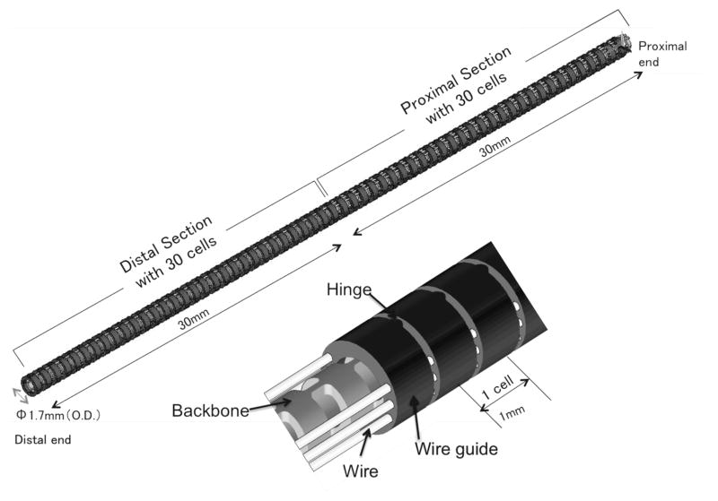
Figure 1 shows the structure of the robot, which is composed of a monolithic backbone, tendon wire, and wire guides. The robot has an outer diameter (O.D.) of 1.7 mm, a length of 60 mm and consists of the two sections, each with one degree of freedom. The robot has a 0.7 mm-diameter tool channel for imaging fibers. Three antagonistic pairs of tendon wires run through the wire guides. The two pairs end at the robot’s midpoint, and the other pair ends at the distal end. The pair of tendon wires was spread apart from 0.65 mm from the centroid of the robot. Through differential variation of the tensions in the tendon wires, the tensions are transduced into torque at the wire guides. The torque bends the backbone at the distal section or the proximal section.
Fig. 1.
Two-sections continuum robot design
The backbone is an elastic tube, with flexible and rigid portions periodically spaced along its length. The wire guides align with the rigid portions so that the torques are applied only at the rigid portions. The flexible portion between two rigid portions and the guides is regarded as a constant-curvature element within one section under bending (hereafter referred to as a “cell”). Each cell has a length of 1 mm, with a bending stiffness of 2.0 × 10⁻² Nm/rad with imaging fiber stiffness for endoscopy. As we discuss below, the cells make kinematic modeling of both uneven curvatures and frictions simple. A material of the backbone and the tendon wires is superelastic nickel-titanium (NiTi) alloy. The wire guides are made of stainless steel. The wire guides have eyelets for holding tendon wires of 0.2 mm diameter. The tendon wires are 0.16 mm diameter wire ropes. The tension limitation is 5 N for one tendon wire due to the distortion tolerance for a linear elastic region (0.5 %). The structure was designed in CAD software, SolidWorks. The bending stiffness of the backbone was calculated by a finite-element analysis software, ANSYS.
Using two sections offers the advantages of active curvature compensation. By actuating two sections independently, the robot can generate a variety of posture combinations with curvatures at the distal and the proximal section while holding the tip angle.
2.2 Kinematic mapping with friction in tendon wire
We formulated the forward kinematic mapping (FKM) of the robot from the input tension in a tendon wire to the posture of the robot. For the FKM, we introduced arc parameters, which are curvature, length of arc and an angle of a bending plane containing the arc, as configuration parameters of the continuum robot. We mapped the tension to the arc parameters followed by mapping from the arc parameters to the posture of the robot to complete the FKM.
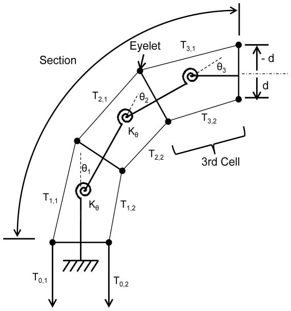
For accurate mapping between the tension and the arc parameters, we introduced a friction model that is a ratio of the tension variation in a tendon wire due to frictional forces between the tendon wire and eyelets in the wire guides. To express this tension variation, we created a concept of “cell.” A cell is a unit of a linear elastic system consisting of a rotational spring, torque arms, and constant tensions within one cell. By concatenating cells, both tension variation and the corresponding curvature variation within one section can be handled in the FKM. Figure 2 shows this decomposition of a single section consisting of three cells.
Fig. 2.
Section consisting of a linear elastic system of cells.
We assumed that system remains in quasistatic equilibrium. Frictional forces are equal to maximum static frictional forces proportional to the normal forces with friction coefficient μ at eyelets. By considering geometrical layout of the tendons and cells, we defined αi,j, which is the ratio of the tension variation in a tendon i between cell j and cell (j+1), as:
| (1) |
where Sgn(x) is Sign function, Tj,i represents the tension in tendon i in cell j, θj is the angular displacement of the distal end in the cell j. The magnitude of di is the distance of tendon i from the centroid of cell j and the sign of di represents the direction of the tendon i from the centroid of cell j.
The rotational spring Kθ of cell j maps the tension in a tendon wire to the arc parameters as:
| (2) |
where κj is the curvature of the cell j and sj is the arc length of the cell j. Since Kθ, sj and di are known parameters, equations (1) and (2) allow us to map the tension in a tendon wire into the curvature by sequential calculation from the cell at the proximal end to the one at the distal end.
For the mapping from the arc parameters to the posture of the robot, we utilized a homogeneous transformation matrix parameterized by the arc parameters in [8] and applied the matrix for the cells. Our approach is completely different from the approach outlined in [8] because the matrix is applied to cells, not sections. The decomposition into cells allows us to calculate the posture of the robot with uneven curvatures by a simple calculation. Moreover, our mechanical design provides good consistency between this kinematic model and physical structure of cells.
2.3 Experimental design
We conducted two sets of studies to validate the advantages of a two-section robot over a conventional one-section endoscope for an angled-view task. The first set assessed the flexibility of the tip position at a 180°-angled view task attained by a 1:1 scale robot by using FKM. The second set validated the postures when positioning the tip flexible at a 180°-angled view by developing a 1:10 scale prototype of the two-section robot.
Performance analysis
We analyzed the flexibility of the tip position at a 180°-angled view as advantageous performance of the two-section robot. The analysis was conducted using FKM with a friction coefficient that we measured experimentally. The averaged measurement value was 0.31 for friction between test pieces of eyelets and wires. All data presented in this section were obtained using this friction coefficient.
To assess the flexibility of the tip position, we defined the tip position along a longitudinal direction of the robot (tip height) as a performance metric. We tabulated maximum, median and minimum values of this metric. The details of the procedure for this analysis are as follows:
First, a 1:1-scale robot with two-sections was analyzed. As the input of the FKM, we generated possible combinations of the tensions in the tendon wires (TproxL, TdistR) or (TproxR, TdistL) at intervals of 0.1 N. There was a minimum pre-tension value in the tendon wires to avoid slack. By inputting these combinations of the tensions in tendon wires to the FKM, we computed a corresponding group of postures for the robot. From this group we selected postures with a tip angle of 180 degrees. From all of these postures, we tabulated maximum, median and minimum values of the tip height.
Second, a one-section endoscope with the same mechanical specifications as the two-section robot was analyzed. We generated the possible tension in a tendon wire TdistR at intervals of 0.1 N as the input for the FKM. Unlike the two-section robot, the one-section endoscope has only one tension as the input. The rest of the procedure to tabulate the tip height was the same as for the two-section robot.
Finally, we compared the tip height at a tip angle of 180 degrees between the two-section robot and one-section endoscope.
Posture validation
To prove the concept of achieving flexibility with an angled view utilizing a two-section robot, we developed a 1:10 scale prototype of the two-section robot manually actuated by the tendon wires (Figure 3). The prototype has an outer diameter of 14.6 mm, a length of 208 mm and consists of the two sections actuated by tendon wires. The prototype had a similar mechanical structure to the 1:1 scale robot.
Fig. 3.
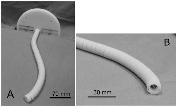
1:10 scale prototype. A: perspective view. B: enlarged view of the tip.
We set 180 degrees as a target angled view. For the input for these views, we converted the tensions in the tendon wires into the pull amount for the tendon wires. After placing the prototype on the surface of a stage, we pulled the tendon wires at these pull amounts and observed the postures of the prototype.
3 Results
3.1 Performance analysis
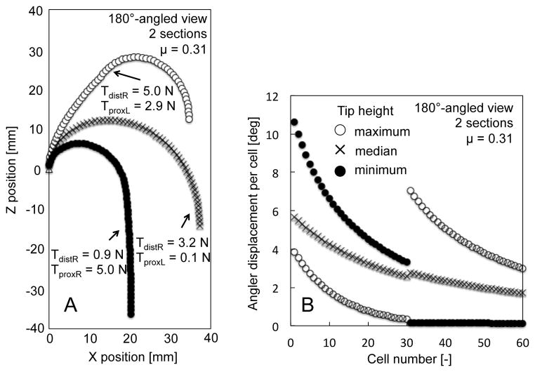
The results of the tip height test at a 180°-angled view are shown in Table 1. The two-section robot had a variety of tip heights from −36.3 mm to 12.5 mm; more than that of the one-section endoscope, which had only one solution at −14.5 mm. The postures of these tip heights are shown in Figure 4A. The two-section robot varied the posture while retaining the tip angle through changes in the tensions of the tendon wires. Figure 4B shows the angular displacement per cell of the two-section robot. From the maximum tip height to the minimum, a cell number with a larger angular displacement shifted from the distal section to the proximal section.
Table 1.
Comparison of tip-height results between two sections and one section.
| Tip height | One section (mm) | Two sections (mm) |
|---|---|---|
| Maximum | - | 12.5 |
| Median | −14.5 | −14.1 |
| Minimum | - | −36.3 |
Fig. 4.
Result of performance analysis of a two-section robot at 180°-angled view. A, Postures of robot grounded at (0,0) mechanically. B, Angular displacement per cell.
3.2 Posture validation
We validated the posture of the two-section prototype at a 180°-angled view (Figure 5A–D). The prototype performed with a variety of tip heights while maintaining a tip angle at 180 degrees by changing the curvature distribution between the two sections. Figure 5 shows three salient postures of maximum (Figure 5B), median (Figure 5C) and minimum (Figure 5D) values of the tip height at a 180°-angled view.
Fig. 5.
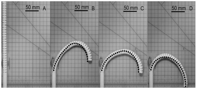
Postures of 1:10 scale prototype at 180°-angled view with prediction by FKM (dots). A: initial straight posture. B: maximum tip height. C: median tip height. D: minimum tip height.
4 Discussion
In this study, we proposed the development and assessment of a multi-section continuum robot to enable a wide-angled visualization and flexible positioning of the tip of an endoscope. In the performance analysis done through forward kinematic mapping (FKM), the two-section robot had a larger variety of tip heights than the one-section endoscope, which had only one height.
The FKM in our study incorporates the piecewise constant-curvature approximation presented in prior art [7, 8]. Likewise, this approximation has been applied to many multi-section continuum robots in the medical field [9–11], because the constant curvature can facilitate analytical frame transformations [8]. In our study, to manage friction in tendon wires for more realistic estimation of the tip position, we introduced cells with good consistency in their physical structures. Because friction is eminent at a large tip angle, our FKM is useful for the analysis of a large-angled-view task.
In summary, we have shown that a two-section continuum robot has an advantage of flexible positioning of the tip at angled-view tasks over one-section endoscopes. This feature can expand the use of the endoscope to inspect around or behind aneurysms without displacing neurovascular structures.
Acknowledgments
Research reported in this publication was supported by Canon USA Inc. and the National Institutes of Health under Award Number P41EB015898, P01CA067165, R01CA138586, R01CA111288, R01CA124377 and R42CA137886.
Footnotes
The content is solely the responsibility of the authors and does not necessarily represent the official views of the National Institutes of Health.
References
- 1.Schievink WI. Intracranial aneurysms. The New England Journal of Medicine. 1997;336:28, 1267. doi: 10.1056/NEJM199701023360106. [DOI] [PubMed] [Google Scholar]
- 2.de Rooij NK, et al. Incidence of subarachnoid haemorrhage: a systematic review with emphasis on region, age, gender and time trends. Journal of Neurology, Neurosurgery, and Psychiatry. 2007;78:1365. doi: 10.1136/jnnp.2007.117655. [DOI] [PMC free article] [PubMed] [Google Scholar]
- 3.Molyneux AJ, et al. International subarachnoid aneurysm trial (ISAT) of neurosurgical clipping versus endovascular coiling in 2143 patients with ruptured intracranial aneurysms: a randomised comparison of effects on survival, dependency, seizures, rebleeding, subgroups, and aneurysm occlusion. Lancet. 2005;366:809. doi: 10.1016/S0140-6736(05)67214-5. [DOI] [PubMed] [Google Scholar]
- 4.Molyneux A, et al. International Subarachnoid Aneurysm Trial (ISAT) of neurosurgical clipping versus endovascular coiling in 2143 patients with ruptured intracranial aneurysms: a randomised trial. Lancet. 2002;360:1267. doi: 10.1016/s0140-6736(02)11314-6. [DOI] [PubMed] [Google Scholar]
- 5.Fischer G, et al. Endoscopy in aneurysm surgery. Neurosurgery. 2012;70:184. doi: 10.1227/NEU.0b013e3182376a36. [DOI] [PubMed] [Google Scholar]
- 6.Taniguchi M, et al. Microsurgical Maneuvers under Side-Viewing Endoscope in the Treatment of Skull Base Lesions. Skull base-an interdisciplinary. 2011;21:115. doi: 10.1055/s-0031-1275248. [DOI] [PMC free article] [PubMed] [Google Scholar]
- 7.Jones BA, et al. Kinematics for multisection continuum robots. IEEE Transactions on Robotics. 2006;22(1):43–55. [Google Scholar]
- 8.Webster RJ, III, et al. Design and Kinematic Modeling of Constant Curvature Continuum Robots: A Review. International Journal of Robotics Research. 2010;29(13):1661–1683. [Google Scholar]
- 9.Camarillo DB, et al. Configuration Tracking for Continuum Manipulators With Coupled Tendon Drive. IEEE Transactions on Robotics. 2009;25 [Google Scholar]
- 10.Webster RJ, III, et al. IEEE Transactions on Robotics. 2009;25:67–78. [Google Scholar]
- 11.Xu K, et al. An investigation of the intrinsic force sensing capabilities of continuum robots. IEEE Transactions on Robotics. 2008;24 [Google Scholar]
- 12.Proust F, et al. Quality of life and brain damage after microsurgical clip occlusion or endovascular coil embolization for ruptured anterior communicating artery aneurysms: neuropsychological assessment. Journal of Neurosurgery. 2009;110:19. doi: 10.3171/2008.3.17432. [DOI] [PubMed] [Google Scholar]


