Abstract
Photoacoustic endoscopy for human urogenital imaging has the potential to diagnose many important diseases, such as endometrial cancer and prostate cancer. We have specifically developed a 12.7 mm diameter, rigid, side-scanning photoacoustic endoscopic probe for such applications. The key features of this endoscope are the streamlined structure for smooth cavity introduction and the proximal actuation mechanism for fast scanning. Here, we describe the probe’s composition and scanning mechanism, and present in vivo experimental results suggesting its potential for comprehensive clinical applications.
Because of the inadequacy of current tools and techniques for diagnosing urogenital diseases [1], such as endometrial cancer, cervical cancer, and prostate cancer, more effective means are desired to achieve accurate medical assessments. Photoacoustic endoscopy (PAE) is an emerging technique that embodies photoacoustic (PA) tomography [2] in a miniaturized probe to enable high-resolution imaging of internal organs with optical absorption contrast. PAE provides structural and functional information by visualizing blood vasculature as well as dye-labeled lymph nodes and vessels in the gastrointestinal tract [3-5] in vivo. Other forms of PA imaging techniques, such as PA microscopy or computed tomography have demonstrated that glucose metabolism and micro-hemodynamics can be monitored in vivo [6,7]. As many neoplasms are associated with angiogenesis and show abnormal metabolic rates, the disease-relevant information provided by PA imaging can potentially facilitate accurate diagnoses.
In recent years, a number of miniaturized PA imaging probes have been reported for various endoscopic applications, such as intravascular [8], urogenital [9,10], and gastrointestinal tract [4] imaging. Among them, however, only two imaging probes that use a micromotor-based mechanical scanning mechanism have demonstrated in vivo imaging with fully encapsulated probe implementations and suitable diameters for endoscopy [4,5]; other imaging probes are not fully encapsulated and/or have not demonstrated in vivo imaging. However, the imaging probes reported in Refs. [4,5] may not be suited for clinical urogenital imaging due to their nonrigidity and slow imaging speed (4 Hz).
The diameter of endoscopic probes for imaging the uterus or prostate are not tightly restricted, as various forms of large-diameter ultrasound probes (usually ~1 cm in diameter) are widely used for many urogenital disease diagnoses in a stand-alone form [11], i.e., without the incorporation with a video endoscopic function. In this study, seeking to apply PAE for diagnosing urogenital diseases, we have implemented a new endoscopic probe with improved imaging speed and a specifically designed probe structure. The key strategy was to use parabolic acoustic reflector-based mechanical scanning with a proximal actuation mechanism, and construct the probe with a durable and safe structure.
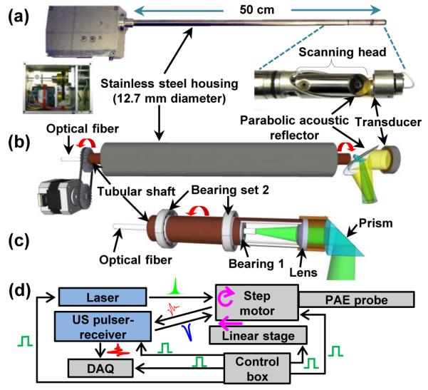
Figures 1(a) shows photos of the side-viewing PA endoscopic probe. The entire endoscopic probe is rigid for convenient handling, and a dome-shaped distal end enables smooth cavity introduction. To encapsulate all endoscope components, we fabricated the probe housing from a medical-grade stainless steel tube (MicroGroup) with an outer diameter of 12.7 mm and a length of ~50 cm. For the mechanical scanning, we employ a scanning head comprised of two key components, a parabolic acoustic reflector (10 mm diameter, nickel substrate, Optiforms) and an optical prism (3 mm diameter, altered from #45-525, Edmund). The scanning head is actuated by a step motor located at the proximal end. The parabolic reflector enables acoustic focusing with a lower geometric aberration than our previous acoustic lens-based focusing method [4,5], while providing a high acoustic numerical aperture (~0.48). Via the prism and parabolic reflector, laser pulses and acoustic waves are delivered coaxially to achieve an efficient overlap of the illumination and acoustic detection over a large depth range.
Fig. 1.

Photo (a) and schematic (b) of the PA endoscopic probe developed for human urogenital system imaging (Media 1). (c) Schematic of the rotary junction (Bearing 1) and light guiding optics. (d) Block diagram showing the peripheral systems.
An ultrasonic (US) transducer (LiNbO3, ~40 MHz, unfocused) generates US pulses and detects both PA and US pulse-echo signals. The US transducer’s piezo-element is a ring with an outer diameter of 8 mm and an inner diameter of 3 mm. The inner diameter matches the diameter of the round optical prism located at the center of the parabolic reflector [Fig. 1(a)]; reducing the transducer’s surface area is also beneficial to the electric impedance matching between the transducer and a signal amplifier. To support the US transducer, we fabricated a bridge-shape stainless steel frame and mounted the transducer at the distal end of the frame. The US transducer’s signal wire (~1 mm thick) passes through the stainless steel bridge, along the 50 cm long probe housing, and is statically connected to a US pulser-receiver (5072PR, Olympus). Because of the bridge section, the angular field-of-view (FOV) of the endoscope is partially blocked, by ~100°.
In Figure 1(b), we present a schematic to illustrate the principle of the mechanical scanning and the configuration of the optical and acoustic components. Inside the stainless steel housing, we coaxially placed a tubular rigid shaft to transfer mechanical torque to the scanning head. However, inside the tubular shaft, we placed a multimode optical fiber (UM22-600, Thorlabs) which is positioned statically along the axis of the endoscope. Thus, only the tubular shaft rotates between the housing and the innermost optical fiber. The main advantage of employing the tubular shaft is that it permits torque transmission without mechanical jitter and eventually enables rotational scanning with a uniform angular step size for the scanning mirror. Also, by employing a step motor that can provide fast and stable rotation, the endoscope achieves much faster mechanical scanning than previous micromotor-based endoscopes [4,5].
As shown in Figure 1(c), we formed a rotary junction (i.e., Bearing 1) near the coupling point between the tubular shaft and scanning head [Fig. 1(a)] to provide a free rotation only to the scanning head, separating it from the optical fiber. The center position of the shaft to the probe housing is sustained by multiple ball bearings (Bearing set 2) placed at the space between the housing and the shaft, over the 50 cm long tubular section; Bearing 1 placed inside the shaft is necessary to make the optical fiber static. Hence, an optical lens (#65-270, Edmund) and the prism inside the scanning head rotate together during the mechanical scanning. Given the optical configuration, the laser beam diameter for PA imaging is ~2.3 mm when it passes through an optically and acoustically transparent polyethylene terephthalate membrane (103-0227, Advanced Polymers). The membrane forms an imaging window and seals the inner cavity of the endoscope, which is filled with de-ionized water. As laser beams are sent to target tissue without optical focusing, the endoscope’s spatial resolution is determined by the geometry of the parabolic reflector and acoustic parameters of the US transducer. For this prototype imaging probe, we set the working distance at ~3.5 mm apart from the probe surface to image endometrial cancer in the uterus, which typically has a wall thickness of ~10 mm.
Figure 1(d) shows the endoscope’s peripheral systems, comprised of a light source, the US pulser-receiver, and a data acquisition (DAQ) system. The light source is a solid-state, diode-pumped Nd:YVO4 laser (INNOSLAB IS811-E, EdgeWave) providing a 532 nm wavelength (~5 ns pulse width). For PA imaging, laser pulses are coupled to the endoscope’s multimode optical fiber (~5 m), which is extended to the distal end of the probe [Fig. 1(b)]. After exiting the optical fiber, they are reflected by the prism and sent to the target tissue to generate PA signals. We applied the total internal reflection effect, and, to maintain the effect after the chamber is filled with acoustic coupling water, we sealed a thin air layer outside the hypotenuse of the prism. The generated PA waves reflected by the parabolic reflector are detected by the US transducer. To record PA and US signals, we utilize a high-speed digitizer (PCI-5124, National Instruments). [4] We also constructed a control box using a multifunction data acquisition card (PCI-6221, National Instruments) to control and synchronize the peripheral systems. Considering the large probe diameter of 12.7 mm, we record 800 A-lines per B-scan, which yields an angular step size of 0.45° for the scanning mirror.
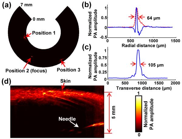
We tested its imaging performance, including the scanning speed, spatial resolution, and imaging depth. As presented in Media 1, our endoscope’s scanning speed could easily reach 22 Hz, thanks to the capacity of the motor. In the imaging experiments to be presented later, however, we recorded data with a 6.25 Hz B-scan frame rate because of the limited pulse repetition rate of the laser system (5 kHz). For the resolution measurement, we utilized a ~20 μm thick tungsten wire as a target and imaged it at three different locations in a water medium; we imaged photoacoustically only because the US resolution relies on two-way acoustic focusing and can be inferred from the PA resolution. Since the imaged tungsten wire had a sufficient length with a diameter smaller than the endoscope’s spatial resolution, the wire could be treated as a line target. For more accurate measurement of resolution, we recorded 50 B-scan images and then averaged them.
Figures 2(a) shows a PA B-scan image that includes the imaged tungsten wire at three different locations. As the target is moved away from the focus (i.e., Positions 1 and 3), the transverse resolution deteriorates. In Figures 2(b) and 2(c), we present radial and transverse line spread functions (LSFs) for the target located at the focal point (i.e., Position 2). Based on the LSFs, we determined the endoscope’s spatial resolutions to be 64 μm and 105 μm in the radial and transverse directions, respectively. These experimental resolutions were worse than the theoretically estimated radial resolution [12] of 39 μm, and 65 μm transverse resolution predicted by Zemax (Radiant Zemax). We speculate that the discrepancies were caused by the distortion of acoustic waves by the optical prism placed at the center of the parabolic reflector. Figure 2(d) shows the endoscope’s image penetration capability, which was determined by imaging a black needle (21 gauge) inserted into the inner leg of an adult Sprague Dawley rat (~450 g, Harlan) in vivo. As shown, the needle was clearly differentiated to a depth of more than 5 mm through the highly scattering tissue, highlighting the endoscope’s eligibility for deep tissue imaging.
Fig. 2.

(a) PA B-scan image of the 20 μm thick tungsten wire imaged at three locations. (b) Typical PA A-line signal (blue) and its Hilbert-transformed signal (i.e., radial LSF) for the tungsten wire target located at the focal point (Position 2). (c) Corresponding transverse LSF of the tungsten wire. (d) PA image of a black needle inserted into the inner leg of a rat.
To demonstrate the endoscope’s in vivo imaging ability, we imaged the colorectum of a New Zealand White rabbit (Harlan). The rabbit was fasted for ~12 hr before the experiment, to increase the likelihood of an empty colon for imaging. Prior to endoscopic imaging, we anesthetized the animal by injecting 15–25 mg/kg ketamine and 2–3 mg/kg xylazine intramuscularly. We cleansed the rabbit’s colon with a saline laxative enema, and spread ultrasound gel into the colon for acoustic coupling. Then, we inserted the probe into the colon and performed endoscopic imaging with a B-scan imaging speed of 6.25 Hz and a laser pulse energy of 0.55 mJ at a 5 kHz repetition rate, which yielded an optical fluence of 13 mJ/cm2 (65% of the ANSI safety limit at the tissue surface [13]). To achieve volumetric imaging, we recorded B-scan images during the constant pullback translation of the probe (200 μm/s) provided by a motorized translation stage. During the imaging procedure, the anesthesia level of the animal was maintained by continuously supplying ~1.5% isoflurane, and the vital signs were also monitored. After the imaging experiment, the rabbit was euthanized by a 150 mg/kg pentobarbital injection via the marginal ear vein.
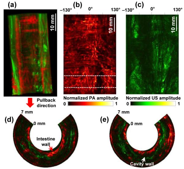
Figure 3(a) shows a three-dimensionally rendered, coregistered PA and US image from the rabbit colorectum acquired in vivo over a scanning time of ~4.5 min. The image was processed from a volumetric data set acquired from a 27 mm diameter and 5.3 cm long image volume (partial images among the entire 1700 coregistered B-scan slices are provided in Media 2). In this experiment, we recorded only data corresponding to a 7 mm imaging depth because the transverse resolutions are degraded in the distant region from the focal point [Fig. 2(a)]; the working distance is 3.5 mm from the probe surface. As shown in PA and US radial maximum amplitude projection (RMAP) images [Figs. 3(b) and 3(c)], which were produced from the volumetric image [Fig. 3(a)], the PA signals acquired at the 532 nm wavelength show vasculature distributed in the colorectum and adjacent organs, while the US signals reveal a spine structure very clearly because of the high acoustic reflection caused by tissue density variation near the cavity wall. In Figures 3(d) and 3(e), we present two combined PA and US B-scan images selected from the marked positions in Figure 3(b). To produce the images, we applied time-gain compensation to more clearly visualize PA signals originating from greater depths. PA imaging shows the cross-sections of blood vessels distributed in the intestine wall, which was estimated to be ~1 mm thick, and detects PA signals from a depth of more than 6 mm.
Fig. 3.

(a) Coregistered PA and US volumetric image from a rabbit colorectum acquired in vivo over a 53 mm range with a 27 mm image diameter (Media 2). The lower portion of the image corresponds to the anus. (b, c) PA- and US-RMAP images of (a). (d, e) Representative combined PA and US B-scan images near the location indicated by the dashed line in (b).
Although the PA imaging experiment provided vasculature information in the colorectum, the imaged blood vessels were not clearly visualized as expected from the resolution values presented in Figure 2. The endoscope’s working distance was about 3.5 mm from the probe surface, while the blood vessels in the imaged colorectum were mostly distributed within ~2 mm of the probe surface [Figs. 3(d) and 3(e)].
To demonstrate the endoscope’s full vasculature resolving ability, we designed a simple experiment that imaged blood vessels positioned near the focal distance of the probe. Such an experimental circumstance was intentionally created by inserting a plastic tubular spacer images are mapped on a linear scale. (13 mm inner diameter, 2 mm wall thickness) around the endoscope’s housing and then imaging blood vessels distributed on the large intestine surface of a rat which was surgically opened. A portion of the tubular spacer’s wall which corresponded to the imaging window of the endoscope was opened to allow PA waves to pass through it, and the gap was filled with ultrasound gel. For this experiment, we utilized the same rat used in the imaging penetration test [Fig. 2(d)] and performed the experiment ex vivo after euthanizing the animal (pentobarbital, 150 mg/kg, IP injection) to avoid distress and possible complications.
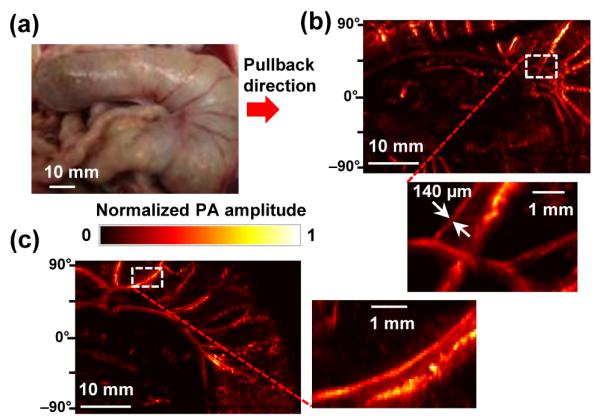
The photograph in Figure 4(a) shows the surface of the large intestine imaged by the PA endoscopic probe in concert with the spacer. As shown in the acquired PARMAP images [Figs. 4(b) and 4(c)], the PA endoscope clearly mapped blood vessels in the intestine wall, as well as neighboring mesenteric tissues (scanning time: ~4 min). Apparent blood vessel diameters in the magnified images are much smaller than those in the PA-RMAP images acquired from the rabbit colorectum in vivo [Figs. 3(b)] and estimated to be as small as ~140 μm, which is comparable with the experimentally quantified spatial resolution value [Fig. 2] and makes the mesenteric blood vessel pair distinguishable. The angular FOVs of the images presented in Figures 4(b) and 4(c) are smaller than the actual FOV because a nearly-planar surface was imaged. All procedures in the animal experiments followed protocols approved by the Institutional Animal Care and Use Committee at Washington University in St. Louis.
Fig. 4.

(a) Photo of the rat large intestine imaged ex vivo. (b, c) PA-RMAP images of (a). All the PA signals in the presented
In this study, we designed and implemented a dual-mode PA and US rigid probe for comprehensive use in human urogenital imaging, and demonstrated its endoscopic workability through animal experiments. The endoscopic probe enabled simultaneous PA and US imaging with a B-scan frame rate of 6.25 Hz, which is currently limited by the pulse repetition rate of the laser system; we demonstrated that the mechanical rotation speed exceeds 20 Hz [Media 1]. Compared with our previous micromotor-based endoscopes [4,5], the main difference in the probe design is that the locations of the US sensor and mechanical actuation source are switched (Fig. 1), while the static mounting strategy of the light delivery and acoustic detection units is maintained. By relocating the mechanical source to the proximal part, a space restriction for the motor was eliminated at the distal end; thereby we were able to use a more powerful motor. Although the detailed endoscope’s design needs to be modified for specific applications, the general design concept and scanning mechanism presented in this paper may be used for various other applications, such as a hand-held exterior or laparoscopic probe.
One disadvantage of this endoscope is the low depth of focus caused by the high acoustic numerical aperture. For this prototype, we aimed the focal distance at 3.5 mm which renders a poor spatial resolution near the probe surface. Applying the integrated optical- and acoustic-resolution imaging concept [10] could increase the transverse resolution over the entire radial imaging range. Our first clinical goal is to apply this endoscope for imaging uteri with endometrial cancers. As the endoscope provides PA images in a coregistered form with traditional US images, which are familiar to clinicians, it would enable more accurate medical assessments for urogenital diseases.
Acknowledgments
We thank Prof. James Ballard for his attentive reading of the manuscript. This work was sponsored in part by National Institutes of Health grants DP1 EB016986 (NIH Director’s Pioneer Award), R01 CA134539, and R01 CA159959. L.W. has a financial interest in Microphotoacoustics, Inc. and Endra, Inc., which, however, did not support this work. K.M. has a financial interest in Microphotoacoustics, Inc.
Footnotes
OCIS Codes: (170.3880) Medical and biological imaging; (170.5120) Photoacoustic imaging; (170.2150) Endoscopic imaging. http://dx.doi.org/10.1364/OL.99.099999
References
- [1].Cannistra SA, Niloff JM. Cancer of the uterine cervix. N. Engl. J. Med. 1996;334(no. 16):1030–1038. doi: 10.1056/NEJM199604183341606. [DOI] [PubMed] [Google Scholar]
- [2].Wang LV, Hu S. Photoacoustic tomography: in vivo imaging from organelles to organs. Science. 2012 Mar.335(80):1458–62. doi: 10.1126/science.1216210. [DOI] [PMC free article] [PubMed] [Google Scholar]
- [3].Yang J-M, Maslov K, Yang H-C, Zhou Q, Shung KK, Wang LV. Photoacoustic endoscopy. Opt. Lett. 2009 May;34(no. 10):1591–3. doi: 10.1364/ol.34.001591. [DOI] [PMC free article] [PubMed] [Google Scholar]
- [4].Yang J-M, Favazza C, Chen R, Yao J, Cai X, Maslov K, Zhou Q, Shung KK, Wang LV. Simultaneous functional photoacoustic and ultrasonic endoscopy of internal organs in vivo. Nat. Med. 2012 Jul.18(no. 8):1297–1302. doi: 10.1038/nm.2823. [DOI] [PMC free article] [PubMed] [Google Scholar]
- [5].Yang J-M, Chen R, Favazza C, Yao J, Li C, Hu Z, Zhou Q, Shung KK, Wang LV. A 2.5-mm diameter probe for photoacoustic and ultrasonic endoscopy. Opt. Express. 2012 Oct.20(no. 21):23944–53. doi: 10.1364/OE.20.023944. [DOI] [PMC free article] [PubMed] [Google Scholar]
- [6].Yao J, Maslov KI, Zhang Y, Xia Y, Wang LV. Label-free oxygen-metabolic photoacoustic microscopy in vivo. J. Biomed. Opt. 2011;16(no. 7):076003. doi: 10.1117/1.3594786. [DOI] [PMC free article] [PubMed] [Google Scholar]
- [7].Yao J, Xia J, Maslov KI, Nasiriavanaki M, Tsytsarev V, Demchenko AV, Wang LV. Noninvasive photoacoustic computed tomography of mouse brain metabolism in vivo. Neuroimage. 2013 Jan.64:257–66. doi: 10.1016/j.neuroimage.2012.08.054. [DOI] [PMC free article] [PubMed] [Google Scholar]
- [8].Wang B, Karpiouk A, Yeager D, Amirian J, Litovsky S, Smalling R, Emelianov S. Intravascular photoacoustic imaging of lipid in atherosclerotic plaques in the presence of luminal blood. Opt. Lett. 2012;37(no. 7):1244–1246. doi: 10.1364/OL.37.001244. [DOI] [PubMed] [Google Scholar]
- [9].Yaseen MA, Ermilov SA, Brecht H-P, Su R, Conjusteau A, Fronheiser M, Bell BA, Motamedi M, Oraevsky AA. Optoacoustic imaging of the prostate: development toward image-guided biopsy. J. Biomed. Opt. 2013;15(no. 2):021310. doi: 10.1117/1.3333548. [DOI] [PMC free article] [PubMed] [Google Scholar]
- [10].Xing W, Wang L, Maslov K, Wang LV. Integrated optical- and acoustic-resolution photoacoustic microscopy based on an optical fiber bundle. Opt. Lett., vol. 2013 Jan.38(no. 1):52–4. doi: 10.1364/ol.38.000052. [DOI] [PMC free article] [PubMed] [Google Scholar]
- [11].Hawes RH, Fockens P. Endosonography. 2010:212. [Google Scholar]
- [12].Zhang C, Maslov K, Yao J, Wang LV. In vivo photoacoustic microscopy with 7 . 6-μm axial resolution using a commercial 125-MHz ultrasonic transducer transducer. J. Biomed. Opt. 2012;17(no. 11) doi: 10.1117/1.JBO.17.11.116016. [DOI] [PMC free article] [PubMed] [Google Scholar]
- [13].Lasers Institute of American National Standard for Safe Use of Lasers. 2007.


