Abstract
We propose a novel automatic fiducial frame detection and registration method for device-to-image registration in MRI-guided prostate interventions. The proposed method does not require any manual selection of markers, and can be applied to a variety of fiducial frames, which consist of multiple cylindrical MR-visible markers placed in different orientations. The key idea is that automatic extraction of linear features using a line filter is more robust than that of bright spots by thresholding; by applying a line set registration algorithm to the detected markers, the frame can be registered to the MRI. The method was capable of registering the fiducial frame to the MRI with an accuracy of 1.00 ± 0.73 mm and 1.41 ± 1.06 degrees in a phantom study, and was sufficiently robust to detect the fiducial frame in 98% of images acquired in clinical cases despite the existence of anatomical structures in the field of view.
1 Introduction
Magnetic Resonance Imaging (MRI) is an advantageous option as an intra-operative imaging modality for image-guided prostate interventions. While transrectal ultrasound (TRUS) is the most commonly used imaging modality to guide core needle prostate biopsy in the United States, the limited negative predictive value of the TRUS-guided systematic biopsy has been argued [1]. To take advantage of MRI’s excellent soft tissue contrast, researchers have been investigating the clinical utility of MRI for guiding targeted biopsies [2]. MRI-guided prostate biopsies are often assisted by needle guide devices [3, 4] or MRI-compatible manipulators [5, 6, 7]. These devices allow the radiologist to insert a biopsy needle accurately into the target defined within the MRI coordinate space.
Registering needle guide devices to the MRI coordinate system is essential for accurate needle placement [3, 4, 5]. These devices are often equipped with MR-visible passive markers to be localized in the MRI coordinate system. Because the locations of those markers in the device’s own coordinate system are known, one can register the device’s coordinate system to the MRI coordinate system by detecting the markers on an MR image. However, the detection and registration of markers on an MR image are not always simple to achieve, because simple thresholding does not always provide robust automatic detection due to noise from other sources such as the patient’s anatomy. Even if the markers are successfully detected, associating them with the individual markers is another hurdle for device-to-image registration. Existing methods rely on specific designs of fiducial frames or MR sequences [3, 4], restricting the device design.
In this paper, we propose a novel method for robust automatic fiducial frame detection and registration that can be applied to a variety of fiducial frame designs. The only requirement for the frame design is that the frame has at least three cylindrical MR-visible markers asymmetrically arranged. The key idea behind the method is that extraction of 3D linear features from cylindrical markers using a line filter is more robust than that of bright spots on the image by thresholding; by matching the cylindrical shapes detected on an MR image and a model of the fiducial frame, one can register the frame to the MRI coordinate system. We conducted phantom and clinical studies to evaluate the accuracy and the detection rate of the method using an existing MRI-visible fiducial frame [4].
2 Methods
2.1 Requirements for a Fiducial Frame
Our method is designed to detect a fiducial frame consisting of multiple MR-visible cylindrical markers on an MR image and register a model of the fiducial frame to the detected markers. The cylindrical markers can be an MR skin marker product, or sealed tubes filled with liquid that produces MR signal. The frame must be rotationally asymmetric to obtain a unique solution in marker registration. The configuration of the fiducial frame is modeled as a model line set { } in our registration algorithm. Each line is described by a pair of position and direction vectors, and ; those vectors represent the coordinates of a point on the line and the direction vector of the line defined in the fiducial frame coordinate system respectively.
2.2 Detection of Cylindrical Markers on MRI
After a 3D or multi-slice MR image of the fiducial frame has been obtained, each individual marker of the frame is automatically segmented on the MR image using the 3D multi-scale line filter [8]. To distinguish the fiducial frame from other anatomical structures, we propose the following filtering steps. First, the line filter is applied to the image of the fiducial frame to highlight the 3D lines that have the same width as the cylindrical markers. The filter can target 3D lines of a specific width by σf, the standard deviation of the isotropic Gaussian function used to estimate the partial second derivatives. The filtered image is binarized with a threshold. At this stage, only the voxels within the line structures are labeled ‘1’, while the remaining voxels are labeled ‘0’. The voxels within the lines are then relabeled so that each segment has a unique voxel value. Each segment is examined based on its volume and dimensions. If the volume in a given segment is within a pre-defined range [Vmin, Vmax], the length and width of the segment are assessed by computing the principal eigenvector of the distribution of the voxels in the segment. The segment is identified as a cylindrical marker only if its length along the principal eigenvector is close to the physical length of the markers. Once the segment is identified as a cylindrical marker , the centroid of the segment is calculated as , and the principal eigenvector as .
2.3 Registration of the Two Line Set
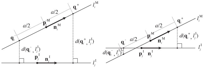
Once the markers are identified as a line set { } on the MR image, the line set in the model { } is registered to { }. The challenge here is that the transformation that registers the model to the MR image cannot be determined analytically, because an one-to-one correspondence between { } and { } has not been established. To address this challenge, we developed an approach similar to the Iterative Closest Line (ICL) [9]. The ICL is a point cloud registration algorithm alternative to the Iterative Closest Points (ICP) [10]; whereas the ICP registers two point clouds by iteratively associating points in the two clouds by nearest-neighbor criteria, the ICL registers them by associating linear features extracted from the point clouds. Unlike ICL, we compute the translation and rotation at once rather than computing them separately. To achieve this, we define a distance function, which becomes zero when two given lines match (Figure 1). The two points on line are defined by and , where the distance between the two points is a. The distances from those points to line are:
| (1) |
| (2) |
Figure 1.

We defined a distance function between one of the lines in the model of the fiducial frame, , and one of the lines extracted from the image, , using the distances from two points and on line to line . and are defined by point , direction vector and the distance to , a/2. The distance function gives zero only if the two lines match. Although the distance function depends on how is chosen, it does not depend on the location of along line . Therefore, the distance function is insensitive to translation along line during the registration process.
If we define the error function for line and line as:
| (3) |
the error function between line and the line set identified on the MRI, , can be defined as:
| (4) |
Finally, the linear transformation is computed by optimizing E using the same iterative approach as in ICP.
2.4 Experimental Setup
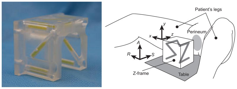
We evaluated the performance of the proposed fiducial detection algorithm using an existing fiducial frame called Z-frame that has been used for registration of a needle-guide template in our clinical study [4]. The existing registration algorithm estimates the position and orientation of the Z-frame with respect to a given 2D image plane based on distances between hyper-intensity dots, where the cylindrical markers intersect the slice plane. Although the automatic registration algorithm for the Z-frame works well for CT images [11], it encounters two problems when used for MRI. First, it often requires manual masking on the input image to exclude anatomical structures that lead to misidentification of tubes. Second, the existing algorithm is specialized for the Z-frame’s shape and does not allow for different shapes. The rationales for using the Z-frame in our evaluation are as follows: 1) it allows direct comparison of registration accuracy with the established method; 2) it allows retrospective tests using existing clinical data, which provide realistic image features e.g. noise and structures other than the fiducial frame, including the patient anatomy.
Phantom Study
We fixed an acrylic base with a scale on the patient table of a 3 Tesla MRI scanner (MAGNETOM Verio 3T, Siemens AG, Erlangen, Germany) to give known translations and rotations to the Z-frame. The scale allows the Z-frame to be placed at 0, 50, 100, 150, and 200 mm horizontally off the isocenter of the imaging bore, and tilted 0, 5, 10, 15, and 20 degrees horizontally from the B0 field. We evaluated the accuracy of the Z-frame registration, while translating the Z-frame along the Z-frame’s X- and Y-axes and rotating around the X-, Y- and Z-axes i.e., roll, pitch and yaw, respectively (Figure 2). The translation along the Z-axis was not considered, since the scanner can position the subject to its isocenter by moving the table. For the acquisition of the 3D images, we used the 3D Fast Low Angle Shot (FLASH) imaging sequence (TR/TE: 12 ms/1.97 ms; acquisition matrix: 256 × 256; flip angle 45°; field of view: 160 × 160 mm; slice thickness: 2 mm; receiver bandwidth: 400 Hz/pixel; number of averages: 3). For each translation and rotation, eight sets of 3D images were acquired. The existing and proposed detection and registration methods were applied.
Figure 2.

A configuration of the Z-frame, which has been used in our clinical trial [4]. The Z-frame has seven rigid tubes with 7.5 mm inner diameters and 30 mm length filled with a contrast agent (MR Spots, Beekley, Bristol, CT) placed on three adjacent faces of a 60 mm cube, thus forming a Z-shaped enhancement in the images.
Clinical Study Using Existing Data
MRI data of the Z-frame were obtained during clinical MRI-guided prostate biopsies performed under a study protocol approved by the Institutional Review Board. Three-dimensional images of the Z-frame acquired at the beginning of each case were collected in 50 clinical cases, where the Z-frame was used to register the needle guide template. We performed automatic registration of the Z-frame using the proposed method. The results were visually inspected by overlaying the Z-frame model on the MRI.
For both studies, we used the medical image computing software, 3D Slicer 4.1 [12] running on a workstation (Apple Mac Pro, Mac OS X 10.7.1, CPU: Dual 6-Core Intel Xeon 2.66 GHz, Apple Inc., Cupertino, CA).
3 Results
Phantom Study
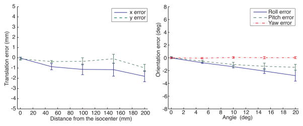
The parameters for the multi-scale line filter [8] were as follows: σf = 3.0, α1 = 0.5, α2 = 2.0. We used threshold for the Hessian matrix = 13.0, [Vmin, Vmax] = [300mm3, 2500mm3], and minimum length of principal axis = 10 mm. Registration of the Z-frame on all MR images was successfully completed without tuning the parameters. Figure 3 shows the errors between translations and rotations of the Z-frame estimated from the proposed registration method and measured on the scale. The average time for computation was 4.3 seconds per image. Table 1 shows a comparison between the registration accuracy of the proposed algorithm and that of the existing algorithm.
Figure 3.
The plots shows the mean and standard deviations of the translational registration errors when the fiducial frame is placed at 0, 50, 100, 150, and 200 mm horizontally off the isocenter and the rotational registration errors when it was tilted 0, 5, 10, 15, and 20 degrees around the X, Y and Z axis of the frame from its original position.
Table 1.
Comparison between the registration accuracy of the existing (original) algorithm and the proposed algorithm using the Mann-Whitney U test.
| X (mm) | Y (mm) | Roll (deg) | Pitch (deg) | Yaw (deg) | |
|---|---|---|---|---|---|
| Original | −1.08 ± 0.80 | −1.44 ± 1.83 | −0.70 ± 0.97 | −1.55 ± 1.55 | 0.04 ± 0.05 |
| Proposed | −1.00 ± 0.73 | −0.38 ± 0.44 | −1.41 ± 1.06 | −0.87 ± 0.66 | 0.01 ± 0.13 |
| p-value | 0.5 | 0.005 | 0.01 | 0.1 | 9.0 × 10⁻⁶ |
Clinical Study using Existing Data
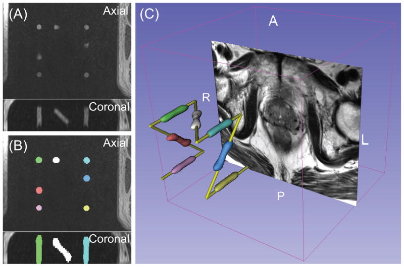
The same parameters were used in the clinical study. Visual inspection of the results (Figure 4) showed that, the Z-frame was successfully registered in 49 cases (98%). In one case, threshold values for minimum and maximum volume of markers had to be adjusted to achieve successful registration. The average computation time was 5.6 seconds.
Figure 4.
(A) The original 3D MR image of the Z-frame acquired in the clinical study presents the sections of the cylindrical markers and the thighs of the patient. (B) The segmented markers are overlaid onto the original MR image. The segmented area was relabeled so that each segment has a unique voxel value presented as unique color. (C) The surface models of the segmented markers are shown with the model of the fiducial frame and an axial slice of T2-weighted prostate MRI in the 3D space.
4 Discussion and Conclusion
In this paper, we proposed a novel method for robust automatic fiducial frame detection and registration that can be applied to a variety of fiducial frame designs. The phantom study demonstrated that the proposed method was capable of registering the model of the fiducial frame to the MRI with an accuracy of 1.00 ± 0.73 mm and 1.41 ± 1.06 degrees. The clinical study demonstrated that the method was sufficiently robust to detect the fiducial frame with a success rate of 98% without any manual operation.
The use of cylindrical markers is essential to the proposed method. Our assumption is that automatic extraction of 3D linear features from cylindrical markers on the input image is more robust than that of spherical markers or sections of cylindrical markers because the Hessian matrix can selectively highlight the linear structures with a specific width, and once the linear structures are extracted, several criteria e.g. volume and size in primary and secondary axes, can be applied to filter out unwanted structures. Moreover, thanks to the approach’s use of lines instead of points, the method is less prone to detection error due to MR signal defects than the other approaches that rely on simple threshold. In practice, signal defects are often caused by bubbles in capsules of liquid-based MR-visible markers. However, the signal defects can still impact the registration accuracy in our approach, because a line is identified as the eigenvectors of the voxel distribution in the segmented markers. This might explain why the registration error of the proposed method was significantly higher than the existing method in Roll but not in the other directions; for the existing technique, only the slices without any signal defect in the markers were manually selected, whereas the proposed method relies on the entire 3D image. Krieger et al proposed the use of template matching to minimize the effect of bubbles [5].
The proposed method provides several advantages over other methods for fully automated device-to-image registration. First, it only relies on passive markers and does not require any embedded coil or MR pulse sequence to enhance the signal from the markers. Second, the algorithm does not assume any particular frame design for automatic detection and registration. The only requirement for the fiducial frame design is the use of more than three cylindrical markers asymmetrically arranged. Such flexibility allows automatic detection and registration of a wide variety of needle guide devices. Third, the algorithm does not require any modification of its implementation in order to be adapted to a particular fiducial frame design. It only requires modifying a model of the frame and parameters, which can be provided as a configuration file. Therefore, even developers who are not specialized in image processing can design and implement device-to-image registration. Those advantages help developers to design needle guide devices with less effort and fewer constraints.
In conclusion, we propose a novel method for robust automatic fiducial frame detection and registration that can be used for a variety of fiducial frame configurations for device-to-image registration in MRI-guided interventions. The phantom and clinical studies demonstrate that the method provides accurate and robust automatic detection and registration of fiducial frames.
Acknowledgments
This work is supported by the National Institute of Health (NIH) (R01CA111288, P01CA067165, P41RR019703, P41EB015898, R01CA124377, R01CA138586), Center for Integration of Medicine and Innovative Technology (CIMIT 11-325), Siemens Seed Grant Award.
References
- 1.Roehl KA, Antenor JA, Catalona WJ. Serial biopsy results in prostate cancer screening study. J Urol. 2002;167(6):2435–9. [PubMed] [Google Scholar]
- 2.Hambrock T, Futterer JJ, Huisman HJ, Hulsbergen-vandeKaa C, van Basten JP, van Oort I, Witjes JA, Barentsz JO. Thirty-two-channel coil 3T magnetic resonance-guided biopsies of prostate tumor suspicious regions identified on multimodality 3T magnetic resonance imaging: technique and feasibility. Invest Radiol. 2008;43(10):686–94. doi: 10.1097/RLI.0b013e31817d0506. [DOI] [PubMed] [Google Scholar]
- 3.de Oliveira A, Rauschenberg J, Beyersdorff D, Semmler W, Bock M. Automatic passive tracking of an endorectal prostate biopsy device using phase-only cross-correlation. Magn Reson Med. 2008;59(5):1043–50. doi: 10.1002/mrm.21430. [DOI] [PubMed] [Google Scholar]
- 4.Tokuda J, Tuncali K, Iordachita I, Song SE, Fedorov A, Oguro S, Lasso A, Fennessy FM, Tempany CM, Hata N. In-bore setup and software for 3T MRI-guided transperineal prostate biopsy. Phys Med Biol. 2012;57(18):5823–40. doi: 10.1088/0031-9155/57/18/5823. [DOI] [PMC free article] [PubMed] [Google Scholar]
- 5.Krieger A, Iordachita I, Guion P, Singh AK, Kaushal A, Menard C, Pinto PA, Camphausen K, Fichtinger G, Whitcomb LL. An MRI-compatible robotic system with hybrid tracking for MRI-guided prostate intervention. IEEE Trans Biomed Eng. 2011;58(11):3049–60. doi: 10.1109/TBME.2011.2134096. [DOI] [PMC free article] [PubMed] [Google Scholar]
- 6.Yakar D, Schouten MG, Bosboom DG, Barentsz JO, Scheenen TW, Futterer JJ. Feasibility of a pneumatically actuated MR-compatible robot for transrectal prostate biopsy guidance. Radiology. 2011;260(1):241–7. doi: 10.1148/radiol.11101106. [DOI] [PubMed] [Google Scholar]
- 7.Zangos S, Melzer A, Eichler K, Sadighi C, Thalhammer A, Bodelle B, Wolf R, Gruber-Rouh T, Proschek D, Hammerstingl R, Muller C, Mack MG, Vogl TJ. MR-compatible assistance system for biopsy in a high-field-strength system: initial results in patients with suspicious prostate lesions. Radiology. 2011;259(3):903–10. doi: 10.1148/radiol.11101559. [DOI] [PubMed] [Google Scholar]
- 8.Sato Y, Nakajima S, Shiraga N, Atsumi H, Yoshida S, Koller T, Gerig G, Kikinis R. Three-dimensional multi-scale line filter for segmentation and visualization of curvilinear structures in medical images. Med Image Anal. 1998;2(2):143–68. doi: 10.1016/s1361-8415(98)80009-1. [DOI] [PubMed] [Google Scholar]
- 9.Alshawa M. ICL: Iterative closest line a novel point cloud registration algorithm based on linear features. Ekscentar. 2007;10:53–59. [Google Scholar]
- 10.Besl PJ, Mckay ND. A method for registration of 3-D shapes. IEEE Trans on Pattern Analysis and Machine Intelligence. 1992;14(2):239–256. [Google Scholar]
- 11.Susil R, Anderson J, Taylor R. A single image registration method for CT-guided interventions. Springer; Heidelberg: 1999. Volume 1679 of LNCS. [Google Scholar]
- 12.Gering DT, Nabavi A, Kikinis R, Hata N, O’Donnell LJ, Grimson WE, Jolesz FA, Black PM, Wells WM. An integrated visualization system for surgical planning and guidance using image fusion and an open MR. J Magn Reson Imaging. 2001;13(6):967–75. doi: 10.1002/jmri.1139. [DOI] [PubMed] [Google Scholar]


