Abstract
Interfacial nanodroplets were grafted to the surfaces of self-sacrificed template particles in a galvanic reaction system to assist the construction of 3D Au porous structures. The interfacial nanodroplets were formed via direct adsorption of surfactant-free emulsions onto the particle surfaces. The interfacial nanodroplets discretely distributed at the template particle surfaces and served as soft templates to guide the formation of porous Au structures. The self-variation of footprint sizes of interfacial nanodroplets during Au growth gave rise to a hierarchical pore size distribution of the obtained Au porous particles. This strategy could be easily extended to synthesize bimetal porous particles such as Au-Pt and Au-Pd. The obtained porous Au, Au-Pt, and Au-Pd particles showed excellent catalytic activity in catalytic reduction of 4-nitrophenol.
Noble-metal particles such as Au, Pt, Pd and bimetallic particles have attracted intense attention due to their unique physicochemical properties and crucial roles in a wide range of applications, such as catalysis, electronics, photonics, environmental sciences, biology and medicine1,2,3,4. Over the past decade, porous Au and Au based alloys were intensively studied as a new class of promising materials5,6,7,8,9. Porous structures not only increase the surface area but also facilitate the mass diffusion, which could enhance the activity of the noble metal, and meanwhile reduce their consumption. Great effort has been devoted to fabricating nanoporous Au10,11,12,13,14,15,16,17. To date, the most widely applied approaches include dealloying, templating and electrochemical synthesis. Dealloying is a selective corrosion and leaching process where the less-stable constituent of an alloy such as Ag in Ag-Au alloys, Cu in Cu-Au alloys, is removed by strong acid or base, remaining a sponge-like nanoporous Au structure10,11,12. In templating strategy, hard templates for instance porous diatom frustules and colloidal crystal templates are used for transcriptive synthesis of Au porous structures15,16,17. A few steps are required to realize the porous structure transcription, including template preparation, modification, Au deposition, and template removing. To scale up the production of porous Au materials for the highly demanded applications, it is still imperative to develop facile and efficient methods for the synthesis of porous Au and its alloys. In addition, synthesis of Au particles with hierarchical pores is still challenging and attractive for both fundamental research and practical applications.
In this work, for the first time we take advantage of interfacial nanodroplets (NDs) as structure guider to construct hierarchical porous Au particles. Interfacial oil droplets are generally formed via anchoring small oil droplets at solid-liquid interfaces18,19,20,21,22,23,24,25. Previously, the interfacial NDs were mainly studied on macroscopic planar solid substrates to investigate their formation, evolution and influence on interfacial properties. Little attention has been paid to the study of interfacial NDs at particle surfaces. The potential application of NDs is hardly explored. Herein, we introduce the interfacial NDs to the hard template particle surfaces in a galvanic reaction system to assist the construction of 3D porous Au structure. Galvanic reactions between  and solid Ag, Cu and Cu2O particles which serve both as reactants and self-sacrificed hard templates, are generally used to prepare Au hollow structures26,27,28,29. However, this strategy is not effective for porous Au synthesis. We found that via simply introducing interfacial NDs onto the surfaces of the self-sacrificed template particles during the galvanic reaction, hierarchical porous Au particles were successfully produced. The interfacial NDs played a key role in the construction of porous structures.
Results
Formation of porous Au particles
Cu2O octahedral particles with an average edge length of ~3.25 μm (See supplementary Fig. S1a) were utilized as sacrificed hard templates since the synthesis of Cu2O is facile and relatively cost-effective30,31. Cu2O octahedral particles were first immersed in water, followed by the addition of HAuCl4 solution to trigger the galvanic reaction between Cu2O and  :
:
 |
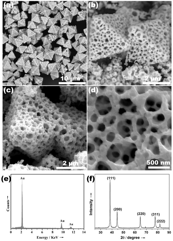
After galvanic reaction, Au nanoparticles were formed and deposited on the surfaces of Cu2O particles. Fig. S1b depicts the obtained particles via direct galvanic reaction between Cu2O and  , from which Au nanoparticles coated Cu2O particles are presented. No obvious pores are observed except the inter-particle spaces. However, if the Cu2O particles were immersed in a surfactant free oil-in-water emulsion solution instead of pure water, while kept other experimental conditions constant, significant structure discrepancy of the obtained particles was realized. As shown in Fig. 1 and Fig. S2, porous particles were produced. The octahedral shape of the obtained porous particle indicates that the shape of template particles (Cu2O octahedra) is successfully transcribed. The average edge length of octahedral porous particles is measured to be about 3.4 μm, which is about 150 nm larger than that of template octahedral particles. Energy dispersive X-ray (EDX) spectrum (Fig. 1e) and X-ray diffraction (XRD) pattern (Fig. 1f) of the porous particles only detect the crystalline Au. The absence of Cu2O signal indicates that the hard template particles were consumed during the reaction. All the data confirm the formation of porous Au particles via the galvanic reaction in the presence of emulsion droplets. Interestingly, a close view of the particle surface (Fig. 1d and Fig. S2a) clearly demonstrates a 3D porous network, but not only a porous shell. Fig. 1b and S2b depict the cracked Au porous particles, from which the 3D porous structure is clearly illustrated. The cracked porous particles produce small porous pieces coexisting with the octahedral Au porous particles. Fig. 1d and Fig. S2a show a hierarchical pore size distribution, from which one can see that the outer pores (300 ~ 650 nm) are larger than the inner pores (50 ~ 140 nm).
Figure 1. Porous Au characterization.
(a–d) SEM images (e) EDX spectrum and (f) XRD pattern of the porous Au particles obtained via galvanic reaction in the presence of emulsions (reaction time is 24 h).
Discussion
Formation mechanism of 3D porous structure
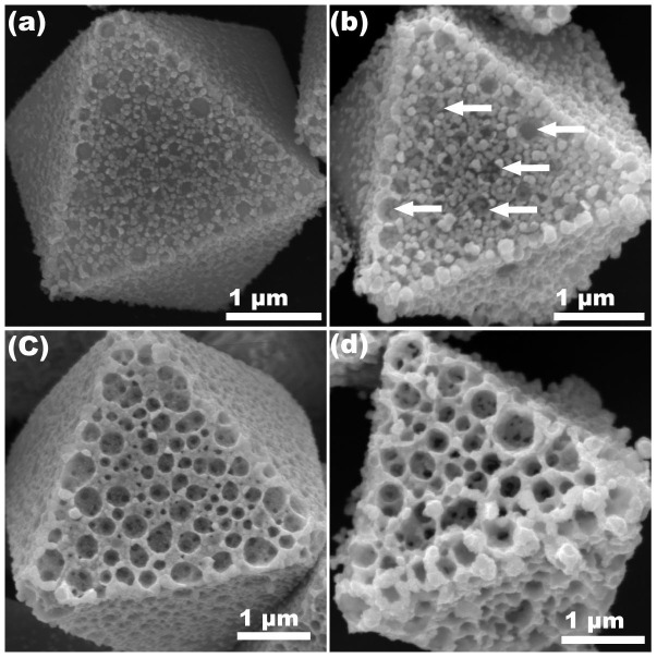
The structural difference between the products obtained via direct galvanic reaction and emulsion presented galvanic reaction indicated that the porous structure was induced by emulsion droplets. To shed light on the function of emulsion droplets and the mechanism in the construction of 3D hierarchical porous structure, time-dependent evolution of the products during the galvanic reaction in the presence of emulsion droplets was monitored. As shown in Figure S1a, primary template Cu2O octahedral particles are with smooth surfaces. After immersing these Cu2O particles in oil-in-water emulsion solution with droplet size of about 145.7 nm (Fig. S3), HAuCl4 was added into the solution to initiate the galvanic reaction. It is found that 10 min galvanic reaction between Cu2O and  gave rise to a porous Au layer formed on the surfaces of Cu2O particles (Fig. 2a). The sizes of pores range from 50 nm to 240 nm. These pores were formed due to the template effect of interfacial NDs. The emulsion droplets could spontaneously adsorb onto the surfaces of Cu2O particles to form the interfacial NDs25, which discretely distributed on the particle surfaces (Fig. 3a). This direct adsorption method has been successfully applied to produce the interfacial NDs at 2D solid substrates20,24. Herein we adopted this concept to particle surfaces. Once the interfacial NDs formed, the NDs capped domains on Cu2O particle surfaces were protected from galvanic reaction because the reactant ions can't penetrate the interfacial NDs composed of oil. Therefore the NDs covered Cu2O surfaces were reserved after galvanic reaction. However, the uncapped domains were exposed for galvanic reaction and consequent Au deposition. Thus Au nanoparticles selectively grew at the uncapped domains, forming the first porous Au layer at the surfaces of Cu2O particles (Fig. 2a and Fig. 3b). After the formation of first porous Au layer, the emulsion droplets subsequently adsorbed onto the as-formed Au layer to form new interfacial NDs thereof (Fig. 3c). These newly formed NDs also served as the templates for the deposition of second porous Au layer on top of the first porous Au layer (Fig. 3d). As show in Fig. 2b, when the reaction time was prolonged to 1 h, the trace of the second porous Au layer was observed. The arrowed parts in Fig. 2b clearly show some larger Au pores formed on the top of the first porous Au layer. The outward growth of second Au layer on the top of first Au layer was caused by Kirkendall effect and Fick's diffusion32,33,34,35, which has been widely applied in solid-liquid reaction to produce hollow structures. During this process, with the proceeding of galvanic reaction, newly generated Au nuclei or clusters diffused outward due to concentration gradient, and finally deposited at the surface of the first porous Au layer in the presence of interfacial NDs. Thus form the second Au porous layer (Fig. 2b). Further prolonging the reaction time (6 h) led to a distinguishable second porous Au layer as shown in Fig. 2c. The continuous growth of Au gave rise to a 3D porous framework (Fig. 2d and Fig. 1a–d).
Figure 2. Time-dependent evolution of the products.
SEM images of the particle surfaces obtained at different galvanic reaction time (a) 10 min, a porous Au particle layer formed at the surface of Cu2O, (b) 1 h, trace of second porous layer formed on the top of the first porous Au layer, (c) 6 h, clear second porous layer formed, (d) 12 h, 3D porous Au structure formed.
Figure 3. Process of construction of 3D porous Au.

(a) Formation of interfacial NDs at the surface of Cu2O particle via direct adsorption of emulsions, (b) Formation of first porous Au layer via galvanic reaction between Cu2O and HAuCl4 in the presence of interfacial NDs, (c) Formation of new interfacial NDs at the as-formed Au porous layer surface via continuous adsorption of emulsions, (d) formation of second porous Au layer on the top of the first Au layer via galvanic reaction in the presence of interfacial NDs. This process continued until the formation of 3D porous structure. (Side view of a part of particle surface).
Hierarchical pore size distribution
Interestingly, it is noticed that the pores in second porous Au layer (Fig. 2b,c) are much larger than that in the first porous Au layer (Fig. 2a), which agrees well with pore size distribution observed in 24 h products (Fig. 1d). The remarkable size discrepancy between the pores in the first and second Au layers is due to the different footprint sizes of the interfacial NDs (templates) at Cu2O and Au surfaces (Fig. 4). The contact angle of an oil droplet at solid surface under water can be estimated according to the Young's equation for the contact angle of a liquid-liquid-solid three-phase system36:
 |
Where γOA, γWA, and γOW are surface tensions of the oil/air, water/air, and oil/water interfaces, respectively. θOW, θO, and θW are the contact angles of oil in water, oil in air and water in air. According to this equation, a solid surface which is hydrophobic in air (large θW, and small value of cosθW) is oleophilic under water, i.e. the oil droplets have smaller contact angle θOW at hydrophobic solid surface than that at hydrophilic surface under water37. Assuming there is no volume lost after the adsorption of emulsion droplets onto particle surfaces to form interfacial NDs, the smaller contact angle of NDs at hydrophobic surfaces renders a larger footprint and vice versa (Fig. 4). Therefore interfacial NDs at hydrophobic surfaces could serve as templates for larger pores, while NDs at hydrophilic surfaces produce smaller pores. Herein, the as-formed Au surface is relatively hydrophobic because the absence of surfactant, while the surface of Cu2O is relatively hydrophilic due to the termination of metal-OH bond (Fig. S4). Therefore, according to equation (2), the interfacial NDs spread well on the Au surfaces, occupying and protecting more surface area (Fig. 4). As a result, larger pore sizes were produced in the second porous Au layer.
Figure 4. Footprint sizes of interfacial NDs at different solid surfaces under water.
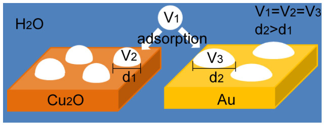
When an emulsion droplet adsorbs onto the relatively hydrophilic Cu2O particle surface and relatively hydrophobic Au surface separately via direct adsorption of emulsion droplet, the formed interfacial NDs have the same volume (V2 = V3 = V1). The ND has relatively larger contact angle at Cu2O surface than that at Au surface. The diameter of the footprint of NDs at Cu2O surface (d1) is smaller than that at Au surface (d2).
Synthesis of bimetallic porous particles
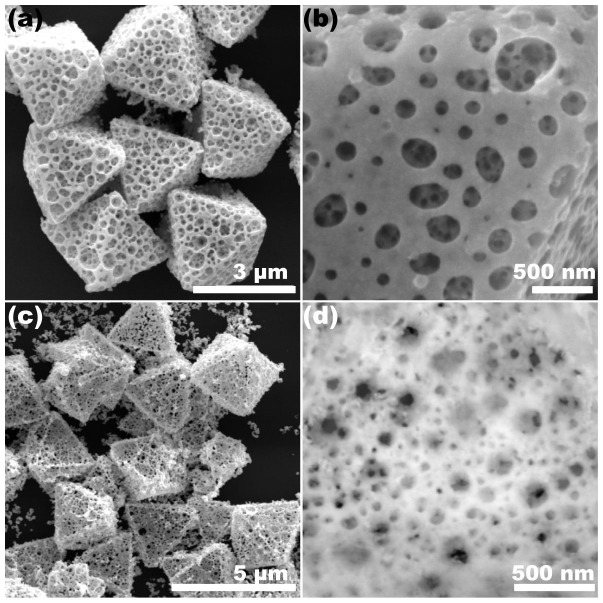
This strategy could be extended to synthesize Au-Pt, and Au-Pd bimetal particles with 3D porous structure, via simply adding a certain amount of H2PtCl6 and H2PbCl4 solution into the reaction system. Fig. 5a,b are typical SEM images of the Au-Pt porous particles obtained after 24 h galvanic reaction, from which one can see the similar 3D hierarchical porous structures. The outer layer pores are much larger than the inner ones. The EDX spectrum (Fig. S5a) confirms the co-existence of Au and Pt elements in the 3D porous particles. SEM images of Au-Pd particles are shown in Fig. 5c,d, confirming the formation of porous structure. The corresponding EDX spectrum of Au-Pd porous particles is shown in Fig. S5b, both the elements of Au and Pd are detected.
Figure 5. Bimetal porous particles.
SEM images of (a) and (b) Au-Pt porous particles, (c) and (d) Au-Pd porous particles synthesized via galvanic reaction in the presence of interfacial NDs.
Catalytic performance of the porous particles
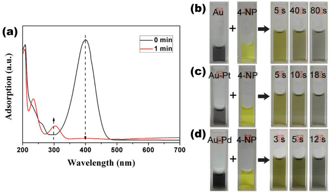
The hierarchical porous structure, especially when the outer layer pores are large and inner layer pores are small, is believed to be favourable for the catalytic application since large pores can increase the diffusion efficiency while the small pores increase the surface area. To testify the catalytic activity of Au, Au-Pt and Au-Pd porous particles, liquid-phase reduction of 4-nitrophenol (4-NP) by NaBH4, which is a model reaction to evaluate the performance of Au catalyst was conducted38,39,40,41,42,43,44,45,46,47,48. Adding NaBH4 into 4-NP solution will produce 4-nitrophenolate with an adsorption peak at 400 nm (yellow colour). Without adding catalyst, the adsorption didn't change, implying the reduction can't proceed without catalysts. When a trace amount (~0.5 mg) of porous Au particles was added to the solution, the yellow colour rapidly faded within 2 min at 298 K (Fig. 6a, b). Because the exceedingly fast reduction, we can only capture the UV-vis spectra for the initial solution and the final solution (Fig. 6a). An isosbestic point at 313 nm is observed, which is same as the reported data39,40,41,42,43,44, indicating that the catalytic reaction only produces 4-aminophenol (4-AP) without any byproduct. The process of the catalytic reaction was also recorded by the video (See supplementary Video 1), from which one can clearly see that the whole process of catalytic reduction of 4-NP finished within 2 min. Because of the large excess of reductant NaBH4 (C(NaBH4)/C(4-NP) = 400:1), the reaction should be considered as a pseudo-first-order reaction with regards to 4-NP only. The linear relationships between ln(Ct/C0) against reaction time are used to calculate the rate constant (ka). Porous Au particles show very high ka value of about 0.75 min−1 at 298 K. The catalytic activity of Au-Pt was also investigated via the same catalytic reaction. It is found that the Au-Pt possessed even higher catalytic activity than that of porous Au particles. With same amount of catalyst, the reduction of 4-NP finished within 20 s (Fig. 6c). The ka value reaches ~3.3 min−1 at 298 K. The video (supplementary Video 2) records the process of the unprecedented fast catalytic reduction of 4-NP. The Au-Pd alloy porous particles showed even higher catalytic activity than Au, and Au-Pt particles. The catalytic reduction finished within 12 s (Fig. 6d, supplementary Video 3), the corresponding ka value is higher than 4 min−1 at 298 K, which is much higher compared to the data reported in the literatures. In addition, the activation energy (Ea) of the reaction was calculated based on the Arrhenius equation:
 |
where A is a constant of the Arrhenius factor, Ka is the rate constant, T (in Kelvin) is reaction temperature, R is the universal gas constant. The catalytic reduction of 4-NP was conducted at three different temperatures 292, 298, and 302 K with porous Au, Au-Pt and Au-Pd particles as catalysts. The obtained reaction rate constant ka is listed in Table S1. The plots of ln ka versus 1000/T show linear curves for 4-NP reduction with porous Au, Au-Pt, Au-Pd particles as catalysts (Fig. 7). From the slope, the apparent activation energy was calculated to be about 34 KJmol−1 for porous Au, 30 KJmol−1 for porous Au-Pt and 28 KJmol−1 for porous Au-Pd respectively. These values are comparable to that reported for nano-sized Au particles43,44,45,46,47,48, for instance the Au nanoboexes (44 KJmol−1) and nanocages (28 KJmol−1)42, Au nanoparticles immobilized on anion-exchange resin (31 KJmol−1)44, Au nanoparticles deposited on poly(methyl methacrylate) particles (38 KJmol−1)45, Au nanodrods stabilized by CTAB (38 KJmol−1)46, and Au nanoparticles immobilized on spherical polyelectrolyte brushes (43 KJmol−1)48 etc. The outstanding catalytic activity of Au, Au-Pt and Au-Pd porous particles should be attributed to their special porous structures. These 3D hierarchical porous Au, Au-Pt, ad Au-Pd particles are promising catalysts.
Figure 6. Catalytic performances.
(a) Time-dependent UV-vis spectra of the reaction solution catalysed by porous Au particles. Photographs of the reaction solution catalysed by (b) porous Au, (c) porous Au-Pt, and (d) porous Au-Pd particles.
Figure 7. Activation energy.
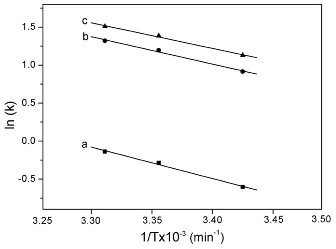
Arrhenius plots of the rate constant (Ka) versus time (1000/T) for 4-NP reduction at different temperature catalyzed by (a) porous Au, (b) porous Au-Pt and (c) porous Au-Pd particles.
In summary, we successfully introduced the interfacial NDs onto the particle surfaces in the galvanic reaction system to construct hierarchical porous Au particles. The synthetic process is facile and cost-effective, and is extendable for the synthesis of Au-Pt, and Au-Pd porous particles. During the galvanic reaction and deposition of porous Au layers, the emulsion droplets continuously adsorbed to the as-formed porous Au surfaces to subsequently serve as templates for the formation of new porous Au layers, leading to the 3D porous structure. The variation of footprint sizes of the NDs at Cu2O and Au surfaces during synthesis caused the hierarchical pore size distribution of the porous particles. The obtained porous Au, Au-Pt, and Au-Pd particles show excellent catalytic activity for catalytic reduction of 4-NP to 4-AP. It is expected that the interfacial NDs involved synthetic strategy could be adapted for other porous materials via solid-liquid reactions, which is focus of our ensuing work.
Methods
Materials
Hydrogen tetrachloroaurate hydrate (99.9%, metal basis) was purchased from Alfa Aesar. Chloroplatinic acid hydrate (H2PtCl6), Pdlladium (II) chloride (PdCl2), Copper acetate hydration (Cu(CH3COO)2·H2O), glucose, hexadecane, acetone, Dopamine hydrochloride, 4-Nitrophenol (4-NP), Sodium borohydrate (NaBH4), ammonia 30% solution, HCl and NaOH were purchased from Sigma-Aldrich and used without purification. Milli-Q water used has a resistance of ~18.2 MΩ cm−1.
Preparation of Cu2O octahedra
A copper acetate aqueous solution (5 mL, 0.3 M) was prepared in a glass vial. 3 mL of 3 M NaOH was added dropwise under vigorous stirring. The blue precipitate of Cu(OH)2 was formed quickly. After continuously stirring for 15 min, 0.06 g glucose was added. The mixture was then stirred for another 5 min before heating in a water bath at 70°C. After 5 min incubation, the brick red product of Cu2O was collected and washed by Milli-Q water and ethanol several times. The obtained Cu2O particles were dispersed in 2 ml of ethanol. 10 μL of Cu2O ethanol suspension was then deposited on a silicon wafer (Cu2O-Si wafer) and dried for further experiments.
Preparation of hexadecane-in-water emulsion
The surfactant free hexadecane-in-water emulsion was prepared by solvent shifting method49,50. A trace of hexadecane was added to acetone at a volume fraction of 0.1%. The required emulsion was synthesized by injecting the acetone solution into large volume (X 20) of Milli-Q water quickly.
Preparation of porous Au, Au-Pt and Au-Pd particles
Porous Au particles: A Cu2O-Si wafer was immersed into 20 mL of hexadecane-in-water emulsion for 20 min for emulsion droplets adsorption. Then, 2 mL of 2.9 mM HAuCl4 was added dropwise to the solution. The reaction was incubated for 10 min, 30 min, 6 h, 12 h, and 24 h separately. Then the wafer was taken out from the reaction solution and washed by water and ethanol.
Porous Au-Pt and Au-Pd particles: A Cu2O-Si wafer was immersed into 20 mL of hexadecane-in-water emulsion for 20 min. 1.7 mL of 2.9 mM HAuCl4 was added dropwise to that emulsion. The reaction was incubated for 1 hour. Then 0.3 mL of 2 mM H2PtCl6 or 0.6 mL of 1 mM H2PdCl4 was added. The reaction was incubated for another 23 hours. And finally, the wafer was washed by water and ethanol several times for characterizations.
Before conducting the catalytic reaction, the possible residual of template particles (Cu2O) was dissolved via immersing the sample-wafer in 15% ammonia aqueous solution for 24 h. As mentioned in the manuscript, we noticed that the porous Au, Au-Pt and Au-Pd particles are hydrophobic. They aggregated heavily during wash and centrifugation. Therefore, before peeling of the porous particles from Si water, the sample-Si wafer was placed in dopamine solution (0.5 mg/ml) for 5–10 min for the ligand adsorption. The catechol group of dopamine has strong metal-binding ability51, which guarantees the colloidal stability of the porous metal particles (catalysts). After the Cu2O removing, the porous metal particles were washed by water several times. They were dispersible in water and used as catalysts.
Catalytic reduction of 4-nitrophenol
The catalytic reduction of 4-NP was executed in a quartz cuvette and monitored by UV-vis spectroscopy and video. In a typical procedure, 0.1 mL of 5 mM 4-NP solution was prepared and mixed with 1 mL of fresh 0.2 M NaBH4. 1 ml of catalysts solution (0.5 mg/ml) was pipetted into the cuvette containing above solution. Then the reduction of 4-NP was recorded by UV-vis spectroscopy. For the curve of reaction time t = 0, it was measured by replacing 1 ml of catalysts solution with 1 ml of Milli-Q water. The process of the catalytic reductions was also recorded by video.
Characterizations
Scanning electron microscopy (SEM) images and energy dispersive X-ray spectrum (EDX) were conducted with FEI Quanta 450 operated at 10–20 kV. The powder X-ray diffraction (XRD) analysis was performed with a ScintagARL X'tra diffractometer. Size distribution of hexadecane-in-water emulsion droplets was measured on Malvern zetasizer nano ZS. UV-vis adsorption spectra were recorded with Shimadzu UV-2600 UV-Vis spectrophotometer. Contact angles were determined by a video-based DataPhysics, OCAH 200.
Author Contributions
H.X. conceived this work. H.X. and A.M. designed the experiment. A.M and J.X. conducted the experiment. H.X., B.Z., D.W. and X.Z. discussed and analysed the data. A.M. and H.X. wrote the manuscript. All authors contributed to the manuscript.
Supplementary Material
Supplementary information
Video 1
Video 2
Video 3
Acknowledgments
This work is supported by the Australia Research Council (DE120100042, DP110104179, DP120102959) and University of South Australia.
References
- Chen A. & Holt-Hindle P. Platinum-Based Nanostructured Materials: Synthesis, Properties, and Applications. Chem. Rev. 110, 3767–3804 (2010). [DOI] [PubMed] [Google Scholar]
- Xia Y. N., Xiong Y. J., Lim B. & Skrabalak S. E. Shape-Controlled Synthesis of Metal Nanocrystals: Simple Chemistry Meets Complex Physics? Angew. Chem. Int. Ed. 48, 60–103 (2009). [DOI] [PMC free article] [PubMed] [Google Scholar]
- Newton M. A. Dynamic adsorbate/reaction induced structural change of supported metal nanoparticles: heterogeneous catalysis and beyond. Chem. Soc. Rev. 37, 2644–2657 (2008). [DOI] [PubMed] [Google Scholar]
- Liz-Marzán L. M. Tailoring Surface Plasmons through the Morphology and Assembly of Metal Nanoparticles. Langmuir 22, 32–41 (2005). [DOI] [PubMed] [Google Scholar]
- Wittstock A., Zielasek V., Biener J., Friend C. M. & Baumer M. Nanoporous Gold Catalysts for Selective Gas-Phase Oxidative Coupling of Methanol at Low Temperature. Science 327, 319–322 (2010). [DOI] [PubMed] [Google Scholar]
- Wittstock A., Biener J. & Baumer M. Nanoporous gold: a new material for catalytic and sensor applications. Phys. Chem. Chem. Phys. 12, 12919–12930 (2010). [DOI] [PubMed] [Google Scholar]
- Ding Y. & Chen M. W. Nanoporous Metals for Catalytic and Optical Applications. MRS Bull. 34, 569–576 (2009). [Google Scholar]
- Biener J. et al. Surface-chemistry-driven actuation in nanoporous gold. Nat. Mater. 8, 47–51 (2009). [DOI] [PubMed] [Google Scholar]
- Zielasek V. et al. Gold catalysts: Nanoporous gold foams. Angew. Chem. Int. Ed. 45, 8241–8244 (2006). [DOI] [PubMed] [Google Scholar]
- Ding Y., Kim Y. J. & Erlebacher J. Nanoporous gold leaf: “Ancient technology”/advanced material. Adv. Mater. 16, 1897–1900 (2004). [Google Scholar]
- Erlebacher J., Aziz M. J., Karma A., Dimitrov N. & Sieradzki K. Evolution of nanoporosity in dealloying. Nature 410, 450–453 (2001). [DOI] [PubMed] [Google Scholar]
- Yu H. D., Zhang Z. P. & Han M. Y. Metal Corrosion for Nanofabrication. Small 8, 2621–2635 (2012). [DOI] [PubMed] [Google Scholar]
- Li C., Wang H. & Yamauchi Y. Electrochemical Deposition of Mesoporous Pt–Au Alloy Films in Aqueous Surfactant Solutions: Towards a Highly Sensitive Amperometric Glucose Sensor. Chem. Eur. J. 19, 2242–2246 (2013). [DOI] [PubMed] [Google Scholar]
- Yanson A. I. et al. Cathodic Corrosion: A Quick, Clean, and Versatile Method for the Synthesis of Metallic Nanoparticles. Angew. Chem. Int. Ed. 50, 6346–6350 (2011). [DOI] [PMC free article] [PubMed] [Google Scholar]
- Bao Z. H., Ernst E. M., Yoo S. & Sandhage K. H. Syntheses of Porous Self-Supporting Metal-Nanoparticle Assemblies with 3D Morphologies Inherited from Biosilica Templates (Diatom Frustules). Adv. Mater. 21, 474–478 (2009). [Google Scholar]
- Bao Z. H. et al. Chemical reduction of three-dimensional silica micro-assemblies into microporous silicon replicas. Nature 446, 172–175 (2007). [DOI] [PubMed] [Google Scholar]
- Nyce G. W., Hayes J. R., Hamza A. V. & Satcher J. H. Synthesis and characterization of hierarchical porous gold materials. Chem. Mater. 19, 344–346 (2007). [Google Scholar]
- Zhang X. H. et al. From transient nanodroplets to permanent nanolenses. Soft Matter 8, 4314–4317 (2012). [Google Scholar]
- Méndez-Vilas A., Jódar-Reyes A. B. & González-Martín M. L. Ultrasmall Liquid Droplets on Solid Surfaces: Production, Imaging, and Relevance for Current Wetting Research. Small 5, 1366–1390 (2009). [DOI] [PubMed] [Google Scholar]
- Zhang X. H. & Ducker W. Interfacial oil droplets. Langmuir 24, 110–115 (2008). [DOI] [PubMed] [Google Scholar]
- Zhang X. H. & Ducker W. Formation of interfacial nanodroplets through changes in solvent quality. Langmuir 23, 12478–12480 (2007). [DOI] [PubMed] [Google Scholar]
- Malmsten M., Lindstrom A. L. & Warnheim T. Ellipsometry Study of Interfacial Film Formation in Emulsion Systems. J. Colloid Interface Sci. 173, 297–303 (1995). [Google Scholar]
- Alvarez M., Friend J. R. & Yeo L. Y. Surface vibration induced spatial ordering of periodic polymer patterns on a substrate. Langmuir 24, 10629–10632 (2008). [DOI] [PubMed] [Google Scholar]
- Zhang X. H., Wei X. X. & Ducker W. Formation of Nanodents by Deposition of Nanodroplets at the Polymer-Liquid Interface. Langmuir 26, 4776–4781 (2010). [DOI] [PubMed] [Google Scholar]
- Ma A. et al. Adsorbed emulsion droplets: capping agents for in situ heterogeneous engineering of particle surfaces. Chem. Commun. 49, 11563–11565 (2013). [DOI] [PubMed] [Google Scholar]
- Skrabalak S. E. et al. Gold Nanocages: Synthesis, Properties, and Applications. Acc. Chem. Res. 41, 1587–1595 (2008). [DOI] [PMC free article] [PubMed] [Google Scholar]
- Camargo P. H. C., Xiong Y., Ji L., Zuo J. M. & Xia Y. N. Facile synthesis of tadpole-like nanostructures consisting of Au heads and Pd tails. J. Am. Chem. Soc. 129, 15452–15453 (2007). [DOI] [PubMed] [Google Scholar]
- Sun Y. G. & Xia Y. N. Alloying and dealloying processes involved in the preparation of metal nanoshells through a galvanic replacement reaction. Nano Lett. 3, 1569–1572 (2003). [Google Scholar]
- Fang J. X., Lebedkin S., Yang S. C. & Hahn H. A new route for the synthesis of polyhedral gold mesocages and shape effect in single-particle surface-enhanced Raman spectroscopy. Chem. Commun. 47, 5157–5159 (2011). [DOI] [PubMed] [Google Scholar]
- Kuo C. H. & Huang M. H. Morphologically controlled synthesis of Cu2O nanocrystals and their properties. Nano Today 5, 106–116 (2010). [Google Scholar]
- Xu H., Wang W. & Zhu W. Shape Evolution and Size-Controllable Synthesis of Cu2O Octahedra and Their Morphology-Dependent Photocatalytic Properties. J. Phys. Chem. B 110, 13829–13834 (2006). [DOI] [PubMed] [Google Scholar]
- Zeng H. C. Integrated Nanocatalysts. Acc. Chem. Res. 46, 226–235 (2013). [DOI] [PubMed] [Google Scholar]
- Lou X. W., Archer L. A. & Yang Z. C. Hollow Micro-/Nanostructures: Synthesis and Applications. Adv. Mater. 20, 3987–4019 (2008). [Google Scholar]
- Yin Y. D. et al. Formation of hollow nanocrystals through the nanoscale Kirkendall Effect. Science 304, 711–714 (2004). [DOI] [PubMed] [Google Scholar]
- Xu H., Wang W., Zhu W. & Zhou L. Synthesis of octahedral CuS nanocages via a solid–liquid reaction. Nanotechnology 17, 3649 (2006). [Google Scholar]
- Jin M. et al. Underwater Oil Capture by a Three-Dimensional Network Architectured Organosilane Surface. Adv. Mater. 23, 2861–2864 (2011). [DOI] [PubMed] [Google Scholar]
- Zhong J. et al. Combined Molecular Dynamics and Quantum Mechanics Study of Oil Droplet Adsorption on Different Self-Assembly Monolayers in Aqueous Solution. J. Phys. Chem. C 117, 12510–12519 (2013). [Google Scholar]
- Herves P. et al. Catalysis by metallic nanoparticles in aqueous solution: model reactions. Chem. Soc. Rev. 41, 5577–5587 (2012). [DOI] [PubMed] [Google Scholar]
- Lee J., Park J. C. & Song H. A Nanoreactor Framework of a Au@SiO2 Yolk/Shell Structure for Catalytic Reduction of p-Nitrophenol. Adv. Mater. 20, 1523–1528 (2008). [Google Scholar]
- Ge J., Zhang Q., Zhang T. & Yin Y. Core–Satellite Nanocomposite Catalysts Protected by a Porous Silica Shell: Controllable Reactivity, High Stability, and Magnetic Recyclability. Angew. Chem. Int. Ed. 47, 8924–8929 (2008). [DOI] [PubMed] [Google Scholar]
- Deng Y. et al. Multifunctional Mesoporous Composite Microspheres with Well-Designed Nanostructure: A Highly Integrated Catalyst System. J. Am. Chem. Soc. 132, 8466–8473 (2010). [DOI] [PubMed] [Google Scholar]
- Zeng J., Zhang Q., Chen J. & Xia Y. A Comparison Study of the Catalytic Properties of Au-Based Nanocages, Nanoboxes, and Nanoparticles. Nano Lett. 10, 30–35 (2009). [DOI] [PubMed] [Google Scholar]
- Saha S., Pal A., Kundu S., Basu S. & Pal T. Photochemical Green Synthesis of Calcium-Alginate-Stabilized Ag and Au Nanoparticles and Their Catalytic Application to 4-Nitrophenol Reduction. Langmuir 26, 2885–2893 (2009). [DOI] [PubMed] [Google Scholar]
- Panigrahi S. et al. Synthesis and Size-Selective Catalysis by Supported Gold Nanoparticles: Study on Heterogeneous and Homogeneous Catalytic Process. J. Phys. Chem. C 111, 4596–4605 (2007). [Google Scholar]
- Kuroda K., Ishida T. & Haruta M. Reduction of 4-nitrophenol to 4-aminophenol over Au nanoparticles deposited on PMMA. J. Mol. Catal. A: Chem. 298, 7–11 (2009). [Google Scholar]
- Khalavka Y., Becker J. & Sönnichsen C. Synthesis of Rod-Shaped Gold Nanorattles with Improved Plasmon Sensitivity and Catalytic Activity. J. Am. Chem. Soc. 131, 1871–1875 (2009). [DOI] [PubMed] [Google Scholar]
- Chang Y.-C. & Chen D.-H. Catalytic reduction of 4-nitrophenol by magnetically recoverable Au nanocatalyst. J. Hazard. Mater. 165, 664–669 (2009). [DOI] [PubMed] [Google Scholar]
- Schrinner M. et al. Mechanism of the Formation of Amorphous Gold Nanoparticles within Spherical Polyelectrolyte Brushes. Macromol. Chem. Phys. 208, 1542–1547 (2007). [Google Scholar]
- Aubry J., Ganachaud F., Cohen Addad J.-P. & Cabane B. Nanoprecipitation of Polymethylmethacrylate by Solvent Shifting:1. Boundaries. Langmuir 25, 1970–1979 (2009). [DOI] [PubMed] [Google Scholar]
- Taisne L., Walstra P. & Cabane B. Transfer of oil between emulsion droplets. J. Colloid Interface Sci. 184, 378–390 (1996). [DOI] [PubMed] [Google Scholar]
- Lee H., Dellatore S. M., Miller W. M. & Messersmith P. B. Mussel-inspired surface chemistry for multifunctional coatings. Science 318, 426–430 (2007). [DOI] [PMC free article] [PubMed] [Google Scholar]
Associated Data
This section collects any data citations, data availability statements, or supplementary materials included in this article.
Supplementary Materials
Supplementary information
Video 1
Video 2
Video 3


