Abstract
Introduction
Attenuation correction for magnetic resonance (MR) coils is a new challenge that came about with the development of combined MR and positron emission tomography (PET) imaging. This task is difficult because such coils are not directly visible on either PET or MR acquisitions with current combined scanners and are therefore not easily localized in the field of view. This issue becomes more evident when trying to localize flexible MR coils (eg, cardiac or body matrix coil) that change position and shape from patient to patient and from one imaging session to another. In this study, we proposed a novel method to localize and correct for the attenuation and scatter of a flexible MR cardiac coil, using MR fiducial markers placed on the surface of the coil to allow for accurate registration of a template computed tomography (CT)–based attenuation map.
Materials and Methods
To quantify the attenuation properties of the cardiac coil, a uniform cylindrical water phantom injected with 18F-fluorodeoxyglucose (18F-FDG) was imaged on a sequential MR/PET system with and without the flexible cardiac coil. After establishing the need to correct for the attenuation of the coil, we tested the feasibility of several methods to register a precomputed attenuation map to correct for the attenuation. To accomplish this, MR and CT visible markers were placed on the surface of the cardiac flexible coil. Using only the markers as a driver for registration, the CT image was registered to the reference image through a combination of rigid and deformable registration. The accuracy of several methods was compared for the deformable registration, including B-spline, thin-plate spline, elastic body spline, and volume spline. Finally, we validated our novel approach both in phantom and patient studies.
Results
The findings from the phantom experiments indicated that the presence of the coil resulted in a 10% reduction in measured 18F-FDG activity when compared with the phantom-only scan. Local underestimation reached 22% in regions of interest close to the coil. Various registration methods were tested, and the volume spline was deemed to be the most accurate, as measured by the Dice similarity metric. The results of our phantom experiments showed that the bias in the 18F-FDG quantification introduced by the presence of the coil could be reduced by using our registration method. An overestimation of only 1.9% of the overall activity for the phantom scan with the coil attenuation map was measured when compared with the baseline phantom scan without coil. A local overestimation of less than 3% was observed in the ROI analysis when using the proposed method to correct for the attenuation of the flexible cardiac coil. Quantitative results from the patient study agreed well with the phantom findings.
Conclusions
We presented and validated an accurate method to localize and register a CT-based attenuation map to correct for the attenuation and scatter of flexible MR coils. This method may be translated to clinical use to produce quantitatively accurate measurements with the use of flexible MR coils during MR/PET imaging.
Keywords: magnetic resonance imaging, positron emission tomography, attenuation correction, flexible radio frequency coils
Combined magnetic resonance (MR) and positron emission tomography (PET) imaging is a technology that has been in development for nearly 2 decades.1 The synergy between the 2 imaging modalities has always been desirable because each one provides different but complementary information about the structure and function of tissue. Recently, commercial solutions became available for simultaneous MR and PET brain imaging,2 followed by simultaneous and sequential whole-body scanners.3,4 Indeed, the increase in available scanners has produced a growing body of literature about the potential use of combined MR and PET imaging in a number of different anatomic settings including the brain,2 lungs,5 heart,6 vasculature,7 and neck.8
The development of combined MR/PET imaging has not been without challenges, especially those related to accurate tracer quantification by the PET component. In contrast to stand-alone PET scanners or combined PET/computed tomography (CT) scanners, MR/PET scanners lack a method to directly measure the photon attenuation because of objects in their field of view (FOV). This has prompted the development of new methods for attenuation correction for combined MR/PET imaging. Several studies investigated the validation of newly developed MR-based attenuation correction methods against the well-established and clinically accepted CT-based attenuation correction.9–17 Attenuation correction on the currently available commercial scanners consists of 2 separate attenuation maps that are generated independently and summed up together at reconstruction time.10,13 The first attenuation map is the patient attenuation, which is typically produced by taking the MR image, segmenting it, and assigning linear attenuation correction factors to certain tissue types. Commercial scanners currently available use either a 4-segment method (air, soft tissue, lung, and fat) or a 3-segment method (air, soft tissue, and lung).18,19 Although this concept is simple, its clinical application has been proven to be inconsistent.20 Missegmentation, metal implant artifacts, arm truncation (because the MR FOV is smaller than that of PET), and lack of a bone segment were some of the issues that have been shown to affect quantification using current MR-based attenuation correction methods.20 The second attenuation map is that of the MR hardware (ie, coils and patient table). Several reports have evaluated the attenuation properties of the MR hardware10–12 and concluded that such equipment attenuates the signal significantly and thus requires careful attenuation correction. Magnetic resonance hardware attenuation maps are either transmission-based13 or CT-based.10 A template attenuation map of the entire object is stored in the system, and the scanned part of the hardware is cropped and added to the patient attenuation map before reconstruction. However, methods currently available on commercial scanners can only correct for the attenuation of rigid objects (rigid MR coils, patient table) in their FOV, but they are not sufficient for the attenuation correction of flexible coils, which change shape and position depending on the patient size and the area being imaged.
Here, we report on a method to localize and correct for the attenuation of a flexible MR cardiac coil using a precomputed template attenuation map. We propose to localize the coil using a set of fiducial markers placed on the outer surface of the coil. Using a combination of rigid and deformable registration, we attempted to align and insert a template CT-based attenuation map of the coil to the MR attenuation correction scan for use in PET reconstruction using fiducial markers visible in both the MR and CT images. We then investigated the accuracy of the proposed combination of rigid and deformable registration to align a single template attenuation map of the coil even when it is at a different degree of flexure. Finally, we demonstrated that we can effectively correct for the attenuation of the flexible coil using the proposed registration method in both phantom and patient studies.
MATERIALS AND METHODS
Cardiac Coil
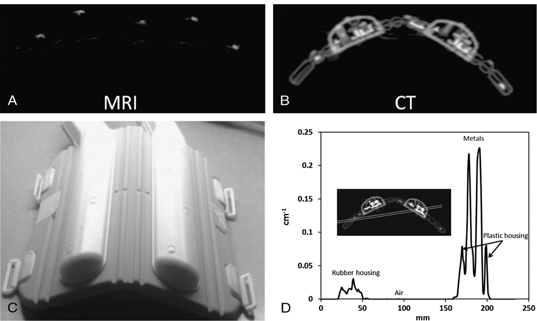
The cardiac coil is a phased array coil that consists of 32 elements. The flexible anterior part of the coil that was used in this study consists of 16 elements. The anterior part of the coil covered approximately 30 cm in the feet-head direction. The design of the cardiac coil used in this study was not optimized for PET transparency. A photograph of the anterior portion of the flexible cardiac coil is shown in Figure 1.
FIGURE 1.
A, Magnetic resonance image of the markers. B, Computed tomography scan of the coil showing the placement of the markers. C, Photograph of the bent coil. D, Line profile across the coil CT attenuation map before clipping the attenuation maps.
Combined MR/PET Imaging
All MR/PET acquisitions in this study were conducted on the Philips Ingenuity TF sequential whole-body scanner (Philips Healthcare, Cleveland, OH). The scanner consisted of 2 separate gantries connected by a rotating patient bed. First, the subjects were scanned using the MR imaging component of the scanner (Achieva 3.0T X Series), followed by a time-of-flight PET scan (Gemini TF). More information about the scanner capabilities and performance is described by Zaidi et al.3 Magnetic resonance imaging scans were done using a T1-weighted 3-dimensional (3D) gradient echo sequence. The following acquisition parameters were applied using the quadrature body coil: flip angle, 10 degrees; echo time, 2.2 milliseconds; repetition time, 4.2 milliseconds; and scan duration, 84 seconds.19 The image voxel size is 2 × 2 × 3 mm (FOV, 576 × 576 × 270 mm). A 3D geometric distortion correction was applied to the MR data to correct for the geometrical distortion. The PET data were acquired for 15 minutes for the phantom study using the scanner’s standard 3D time-of-flight acquisition. The duration between the with– and without–coil acquisitions was 28 minutes. Decay correction was applied to correct for the decay of the tracer between the acquisitions. List-mode data were then corrected for normalization, scatter, random coincidences, attenuation, and dead time. The images were reconstructed using 3D row action maximum likelihood algorithm with 3 iterations and 33 subsets of the data. Computed tomography–based attenuation maps at 511 KeV were generated from the CT images as described.21 Attenuation map values were clipped at 0.12 and 0.02 cm−1 to minimize the overestimation of attenuation of metals as was done in the study of Aklan et al.22 Attenuation correction for patient bed is standard in the system reconstruction.13 In the phantom studies, the CT phantom attenuation map was registered to the non–attenuation-corrected PET image using rigid normalized mutual information maximization registration. All CT-based attenuation maps were resampled to match the PET dimensions before the reconstruction. The final PET image voxel size was 4 × 4 × 4 mm (FOV of 576 × 576 × 180 for the phantom scan and 576 × 576 × 264 for the volunteer scan). Patient acquisition protocols were approved by the Icahn School of Medicine at Mount Sinai institutional review board.
Computed Tomographic Acquisition
All CT scans were conducted on a stand-alone CT scanner (256-slice multidetector CT; Brillance iCT; Philips Healthcare, Cleveland, OH). The acquisition parameters were as follows: voltage, 120 kV; current, 300 mA per slice. The image voxel size is 1.95 × 1.95 × 1 mm. The patient table in the CT scanner was segmented out manually.
Description of the Registration Algorithm
Fifteen MR markers with diameter of 8 mm (MR-SPOTS MRI Skin Markers, ref. no. 185; Beekley Medical, Bristol, CT) were placed on the surface of the coil as shown in Figure 1. The markers were visible on both MR and CT acquisitions. The centroid of each marker was calculated after thresholding the MR image to remove the phantom.
The proposed algorithm for registering a CT attenuation map of the coils to the markers is a 2-step procedure where both registration steps are based solely on the locations of the markers. First, a rigid 3D versor transform that allows for 3D translation and rotation is computed using least-squares minimization. Then, a deformable registration step is applied to the resultant image to “bend” the coil attenuation map. Volume-spline (V-spline) deformable registration was selected on the basis of our comparison of the registration methods (See Comparison of Registration Methods). Mathematical formulation for the V-spline registration is described here.23 After the registration steps, which were performed at the highest resolution, the final registered attenuation CT image was converted to an attenuation map and resampled to match the PET dimensions.
Data Analysis
The overall quantification in the reconstructed PET images is computed by summing up all the counts in the volumetric image. The ROI analysis in this study was done using a 2.5-cm ROI plotted over all axial planes. This size of ROI was selected to investigate the quantitative accuracy in an ROI similar in size to that of small tumors.24 The ROIs were placed either at the top of the phantom where the highest attenuation is expected when uncorrected for coil attenuation (closest to the anterior portion of the coil) or at the bottom of the phantom to quantify the propagation of activity loss.
Evaluation of the Coil Attenuation
To quantify the attenuation properties of the anterior part of the cardiac coil, a uniform cylindrical phantom (height, 30 cm; diameter, 20 cm) was injected with 137.27 MBq of 18F-FDG. The phantom was then scanned with and without the flexible coil, with the markers placed on the coil. In the phantom scan that was done with the coil, the coil was taped tightly to the phantom and the posterior part of the coil to minimize motion during the scan.
Correction of Coil Attenuation Using the CT-Based Coil Attenuation Map
After the MR/PET scans, the phantom and coil assembly was transferred to the CT scanner to generate a reference CT-based attenuation map of the coil and the phantom together. This was done to investigate whether a CT-based attenuation map is a suitable method to correct for attenuation of the coil. The template attenuation map of the coil and phantom assembly was used in the reconstruction of the data collected with the coil present. This attenuation map was registered using only the rigid landmark registration. The reconstructed PET image was then compared with that generated from the phantom-only scan.
Comparison of the Registration Methods
To investigate whether a single attenuation map can be used with our registration technique to fit a wide range of patient habitus, we placed markers on the surface of the coil and acquired a CT scan of the coil at the maximum bend and at an average bend to serve as a reference. Average bend was defined by measuring the bend angle from 3 volunteers. The angle was determined to be 140 degrees. This was done so that a reasonable approximation of the coil deformation would be used as an initial input for the registration workflow. Then, we registered the maximum-bend (angle, approximately 125 degrees) image to the reference image using only the fiducial markers as inputs for the registration. First, a rigid registration step is applied, followed by a deformable registration as described earlier. Several techniques were used in the deformable registration step, including B-spline, thin-plate spline, V-spline, and elastic body spline. Further details on the implementation of the registration methods can be found as previously described.23,25–28 Finally, the Dice similarity metric was computed between the reference and the final registered images to assess the accuracy of the overall registration procedure.29,30
Correction of Coil Attenuation Using a Registered Coil Attenuation Map
Registration of the coil attenuation map to the MR markers using the proposed V-spline registration technique was performed. The coil attenuation map was then added to the phantom attenuation map before reconstruction of the emission data acquired with the coil present. The resultant image from the PET reconstruction using the registered CT-based attenuation map was then compared with that from the phantom-only scan to determine the accuracy of this method to correct for the attenuation of the flexible coil.
Registration Error Calculation
After the registration of the coil attenuation map to the MR markers, we quantified the bias in the registration by computing the mean squared error between the markers in the final registered attenuation map and the markers in the MR image. To explore the effect of the measured registration uncertainty on the reconstructed PET image, the coil attenuation map was shifted in the transaxial direction to simulate the uncertainty in the registration. Emission data acquired with the coil present were then reconstructed with the mis-registered attenuation map and compared with those reconstructed with the registered attenuation map.
Patient Study
To demonstrate the feasibility of our registration method to correct for the attenuation of flexible MR coils in a clinical setting, we injected 506.9 MBq of 18F-FDG to a patient with a family history of cardiovascular disease. To evaluate the attenuation properties across the entire length of the coil, an acquisition of 2 beds for 8 minutes each was performed. The patient was scanned after a radiotracer circulation time of 90 minutes of post-injection with and without the cardiac coil, with the MR markers placed on the outer surface of the coil. The duration between the acquisitions with and without the coil was 25 minutes. Decay correction was applied to correct for the tracer decay between the acquisitions. Emission data acquired with the coil present were reconstructed first either without an attenuation map for the anterior part of the coil or with the coil attenuation map registered to the MR markers to investigate whether the proposed method can be used to correct for the attenuation of the coil.
RESULTS
Quantification of the Coil Attenuation
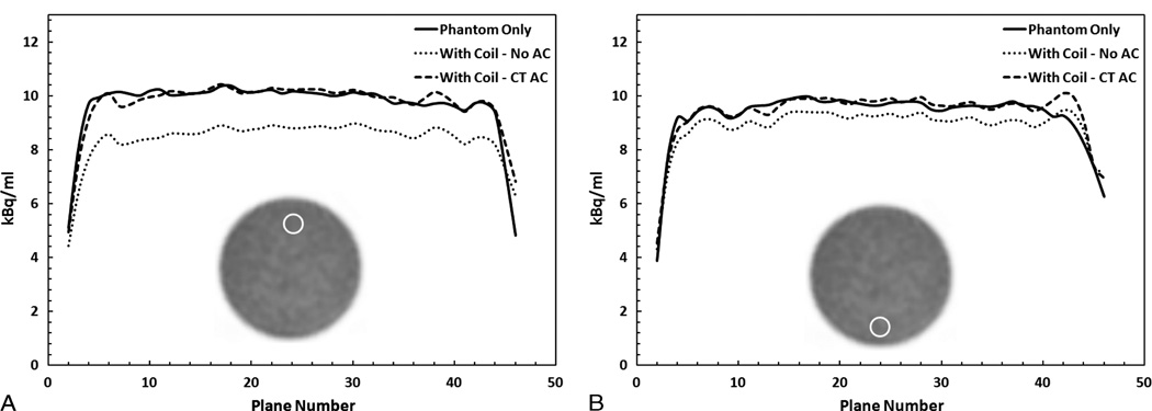
A line profile of attenuation values of the various components before clipping is presented in Figure 1D. The metal components in the coil had the highest attenuation (approximately 0.22 cm−1), followed by the plastic housing (approximately 0.08 cm−1) and finally the rubber housing, which represented the most flexible part of the coil (approximately 0.01 cm−1). The overall reduction in counts in the image due to the presence of the coil is 10%. Local bias in regions close to the coil reached 22% underestimation, as shown by the ROI analysis in Figure 2A. In addition, the effect of the coil on quantification propagates to the bottom of the phantom. Figure 2B shows more than 5% reduction in counts in several planes for the ROIs placed at bottom of the phantom.
FIGURE 2.
Region-of-interest analysis in PET images of the phantom-only scan (Phanton Only) or phantom with the coil scan without correction (With Coil -No AC) or with correction using the template attenuation map (With Coil - CT AC) plotted over all the axial planes. A, Large reduction in the activity of more than 20% in a 2.5-cm ROI placed at the top of the phantom. B, More than 5% reduction in activity was measured at the ROI placed at the bottom of the phantom. CT–based attenuation correction resulted in accurate correction.
Correction of Coil Attenuation Using the CT-Based Coil Attenuation Map
When compared with the acquisition done without the coil, the difference in the overall count was overestimated by 1.4%. Furthermore, the results of the ROI analysis shown in Figure 2 indicated an average overestimation of less than 3% in all axial planes both at the top and bottom ROIs. To establish a bench mark for the variance in the measurements, the standard deviation in a 2.5-cm ROI in the phantom-only image was computed to be 3.1% over all the axial planes. This bench mark was used as the cutoff for acceptable bias.
Registration Flexibility Methods
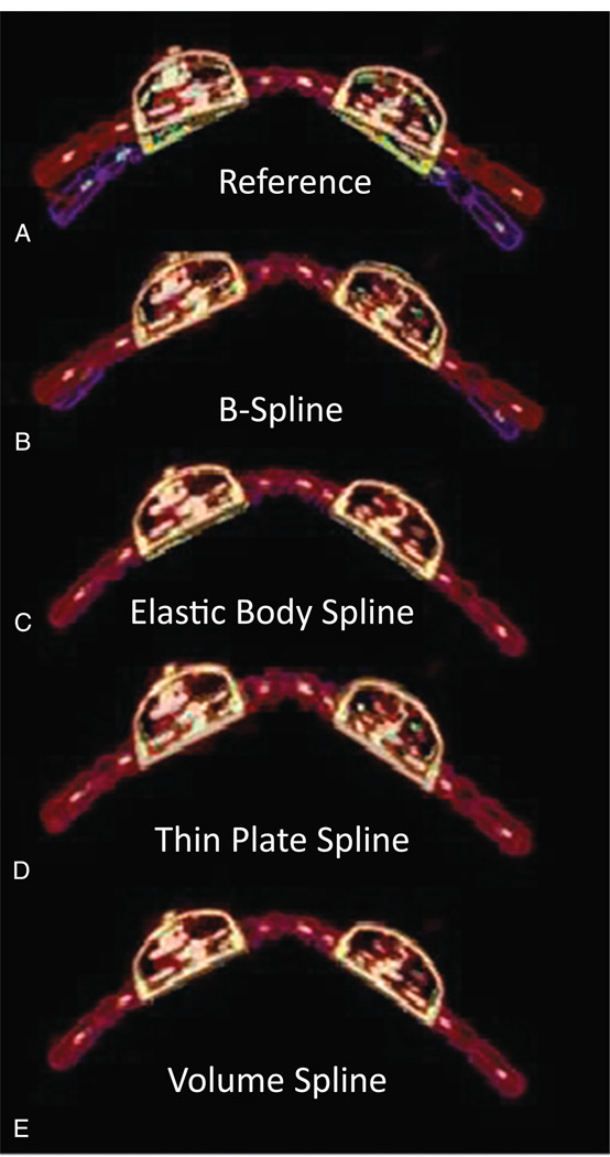
The overlap between the maximum bend and the reference image in addition to the results of the registration is shown in Figure 3. The Dice similarity coefficient and the computation time for each registration method are shown in Table 1. The difference between the maximum bend and the average bend in the reference image was measured to be 7.5 degrees from each side of the coil. The V-spline registration produced the most accurate registration (Dice coefficient, approximately 90%; computation time, 7.2 seconds). Conversely, the B-spline registration produced the least agreement registration (Dice coefficient, approximately 77%; computation time, 8.3 seconds). On the basis of these results, the V-spline registration was used in the remainder of the experiments in this study.
FIGURE 3.
Comparison between deformable registration methods. Overlap between the reference image (hot metal color map) and the maximum bend (A), B-spline (B), elastic body spline (C), thin-plate spline (D), V-spline (E), all in rainbow color map.
TABLE 1.
Summary of Respective Dice Similarity Coefficients and Computation Times Between the Bent Image of the Coil and the Reference Image When Registered With Several Deformable Methods
| Dice Coefficient, % | Computation Time, s | |
|---|---|---|
| Volume | 89.89 | 7.2 |
| Thin-plate | 82.53 | 7.1 |
| Elastic | 88.70 | 13.9 |
| B-spline | 76.92 | 8.3 |
Correction of Coil Attenuation Using a Registered Coil Attenuation Map
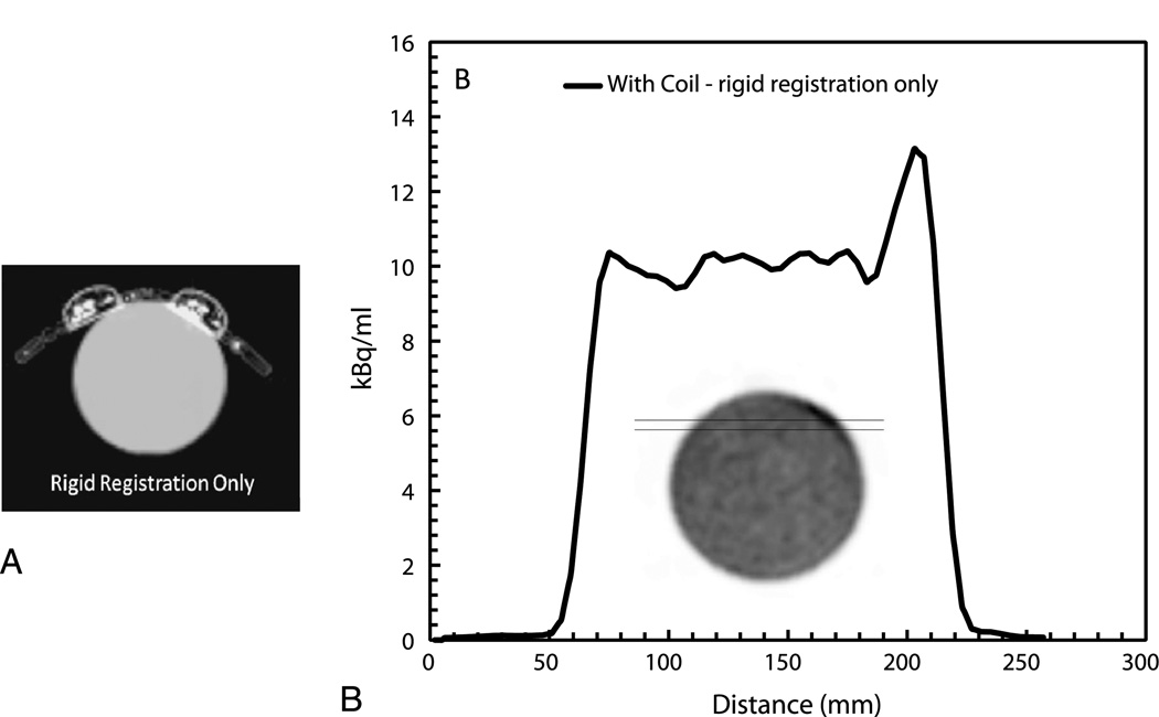
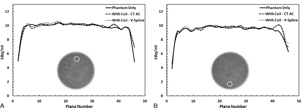
A line profile in Figure 4B demonstrates a large artifact present during the rigid registration only. Conversely, using our proposed 2-step registration technique resulted in only 1.9% overestimation in the overall activity when compared with the image generated from the no-coil acquisition, in addition to no image artifacts. Furthermore, the results of the ROI analysis indicated less than 3% quantitative differences in the ROIs at the top and bottom of the phantom as shown in Figure 5.
FIGURE 4.
A, Attenuation map of the coil over the phantom after the rigid registration only. B, Plot of a profile across the phantom in emission images reconstructed using the attenuation map from (A).
FIGURE 5.
Region-of-interest analysis in PET images of the phantom-only scan (Phantom Only) compared with that acquired with the coil present using the template CT attenuation map (With Coil - CT AC) or a registered coil attenuation map (With Coil - V-Spline). Using our registration technique can accurately correct for the coil’s attenuation as shown in the ROI analysis at the top ROI (A) and the bottom ROI (B).
Registration Error
The mean squared error of the registration was computed to be 1.8 mm averaged over all markers. The coil attenuation map was shifted one-half voxel (2 mm) in the transaxial direction to simulate the inaccuracy in the registration; then, the emission data were reconstructed with the misregistered attenuation maps. The results of this experiment indicated a 1.06% underestimation in the activity when compared with the phantom-only scan.
Patient Study
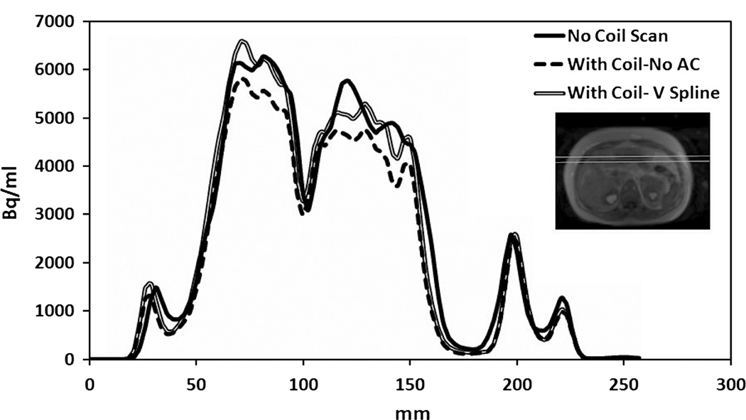
Accuracy of our registration technique is shown in Figure 6. The overall reduction in the counts between the reconstructed image with and without the coil in the volunteer scan was 10.1%. A profile plotted over the reconstructed PET image from the patient-only scan and compared with the patient scan with coil that was reconstructed with or without the coil attenuation map registered to the MR markers is shown in Figure 7. In addition, the measured activity after the attenuation correction for the flexible coil was overestimated by only 2.7% compared with that of the no-coil acquisition.
FIGURE 6.
Overlap between the MR image of a patient including the MR markers attached to the coil and the coil attenuation map. After the V-spline registration, the MR marker aligned with the markers on the coil attenuation map.
FIGURE 7.
A profile was drawn 8 cm under the anterior surface of a patient comparing the acquisition done without the coil (No Coil Scan), the scan done with the coil but without attenuation correction (With Coil-No AC), or with attenuation correction using our registration technique (With Coil - V-Spline).
DISCUSSION
In this study, we addressed the attenuation of flexible MR coils in combined MR/PET imaging. We have shown that attenuation correction for such coils is necessary for accurate quantitative analysis. Furthermore, we proposed and validated a method in both a phantom study and a patient study to localize and correct for such coils.
Several methods of deformable registration were used to deform the coil to match the MR markers. We found that the use of V-spline registration models in the deformation of the coil produced the most accurate registration. Indeed, it was reported that the use of V-spline registration is better suited to deform 3D objects.23 Thin-plate and elastic body spline registrations were able to deform the coil well at the flexible parts but were unable to produce acceptable deformation of the plastic housing of the electronics. The B-spline registration was the most flexible; thus, it would require placement of more markers than other techniques would, especially at the edges of the coil. Because of the smaller MR FOV compared with the PET FOV, the use of B-spline registration is not recommended because the markers at the periphery would likely not be imaged and result in inaccurate registration.
In addition, we investigated several aspects of attenuation correction of the flexible coil. We have shown that the attenuation of such a coil can induce high levels of attenuation making correction necessary for accurate quantitative imaging. We have also shown that the use of CT-based attenuation maps is a feasible solution for the attenuation correction of this coil. Other groups have shown that CT-based attenuation maps can be used in hardware attenuation correction. Delso et al,10 for example, used both CT-based and transmission-based attenuation maps to correct for a head-and-neck coil. The presence of the coil resulted in 17% count loss. Bin et al13 also used both CT- and transmission-based attenuation maps to correct for MR rigid coils and MR patient bed. They reported a count loss of approximately 10% to 20% caused by the patient bed. In agreement with our findings, they reported a slight overcorrection when using CT-based attenuation correction. Such overcorrection when using CT-based attenuation maps could be caused by metal artifacts in the CT image or beam hardening artifacts.11 Most recently, Aklan et al22 investigated the attenuation properties of a breast coil to be used in MR/PET imaging. It was shown that the presence of the coil results in 11% reduction in net true counts. A CT-based attenuation map template was also used to successfully correct for attenuation of the coil.
Accurate alignment of the hardware attenuation map is a critical factor in producing accurate quantification.10 It has been shown that a misregistration of more than 4 mm of a head-and-neck coil can induce bias in PET images.10 Our results indicate that, with the proposed registration method, the maximum measured registration uncertainty was only a maximum of 2.1 mm, less than the spatial resolution of the scanner (4-mm isotropic). However, minor quantitative errors were observed when shifting the coil attenuation map. Taking these results into account, the current registration accuracy is sufficient for accurate quantification.
The attenuation properties of flexible MR coils have been evaluated by Paulus et al.11 Their study used MR fiducial markers and features of the coil distinguishable using ultrashort echo time sequences to locate the coil. A CT-based attenuation map template of the coil, in measurements done on both phantoms and a patient, was then registered to the MR images. The CT-based attenuation maps in that study were registered by only rigid registration, which may not accurately reflect nonrigid movement between CT and MR scans, as demonstrated in this study. Rigid registration also may not accurately address interpatient registration of nonrigid coils, which is a major concern in such protocols. This may lead to a significant bias in quantification (Fig. 4), suggesting that a deformable registration of CT-based attenuation maps for different patients produces more accurate quantification.
In this study, we did not address various configurations of the markers; however, accurate attenuation correction was obtained with the selected configuration. The placement of the markers on and around plastic housing on the coil was done intentionally to accurately capture the flexure of the most attenuating part of the coil. In addition, we only investigated a CT-based attenuation map for the coil. The use of transmission-based attenuation maps for MR hardware has been shown to produce accurate quantification.10,13 In our study, however, CT-based attenuation correction was shown to produce accurate quantification. Finally, we have illustrated our method on 1 patient only as a proof of concept; therefore, several clinical cases must be conducted for a complete clinical evaluation.
CONCLUSIONS
In this study, we presented an accurate attenuation correction method for flexible MR coils in combined MR/PET imaging using a single template attenuation map of the coil determined by a separate CT scan of the coil only. Our method rigidly, then deformably, registers a precomputed attenuation map of the flexible coil to a set of MR markers placed on the outer surface of the coil visualized in both the CT coil attenuation template image and the MR acquisition. We have shown that the registration errors in our technique are minimal and do not induce quantitative or qualitative artifacts in PET quantification. This study has shown that the registration of CT-based attenuation maps of flexible MR coils is a potential solution for correction of attenuation of flexible MR coils in both phantom and patient studies. We have demonstrated the clinical feasibility of the proposed method to register and correct for flexible MR coils during combined MR/PET imaging protocols.
ACKNOWLEDGMENTS
The authors thank Philips Healthcare for its technical support.
sources of funding: Supported by research grants R01 HL071021 and R01 HL078667 from the NIH Heart, Lung and Blood Institute, Bethesda, MD and CTSA UL1TR000067 from the National Center for Advancing Translational Sciences, Bethesda, MD (Dr Fayad).
Footnotes
Conflict of interest
The authors report no conflicts of interest.
REFERENCES
- 1.Shao Y, Cherry SR, Farahani K, et al. Simultaneous PET and MR imaging. Phys Med Biol. 1997;42:1965–1970. doi: 10.1088/0031-9155/42/10/010. [DOI] [PubMed] [Google Scholar]
- 2.Schlemmer HP, Pichler BJ, Schmand M, et al. Simultaneous MR/PET imaging of the human brain: feasibility study. Radiology. 2008;248:1028–1035. doi: 10.1148/radiol.2483071927. [DOI] [PubMed] [Google Scholar]
- 3.Zaidi H, Ojha N, Morich M, et al. Design and performance evaluation of a whole-body Ingenuity TF PET-MRI system. Phys Med Biol. 2011;56:3091–3106. doi: 10.1088/0031-9155/56/10/013. [DOI] [PMC free article] [PubMed] [Google Scholar]
- 4.Delso G, Furst S, Jakoby B, et al. Performance measurements of the Siemens mMR integrated whole-body PET/MR scanner. J Nucl Med. 2011;52:1914–1922. doi: 10.2967/jnumed.111.092726. [DOI] [PubMed] [Google Scholar]
- 5.Platzek I, Beuthien-Baumann B, Langner J, et al. PET/MR for therapy response evaluation in malignant lymphoma: initial experience. MAGMA. 2013;26:49–55. doi: 10.1007/s10334-012-0342-7. [DOI] [PMC free article] [PubMed] [Google Scholar]
- 6.Schlosser T, Nensa F, Mahabadi AA, et al. Hybrid MRI/PET of the heart: a new complementary imaging technique for simultaneous acquisition of MRI and PET data. Heart. 2013;99:351–352. doi: 10.1136/heartjnl-2012-302740. [DOI] [PubMed] [Google Scholar]
- 7.Lobatto ME, Calcagno C, Metselaar JM, et al. Imaging the efficacy of anti-inflammatory liposomes in a rabbit model of atherosclerosis by non-invasive imaging. Methods Enzymol. 2012;508:211–228. doi: 10.1016/B978-0-12-391860-4.00011-2. [DOI] [PMC free article] [PubMed] [Google Scholar]
- 8.Platzek I, Beuthien-Baumann B, Schneider M, et al. PET/MRI in head and neck cancer: initial experience. Eur J Nucl Med Mol Imaging. 2013;40:6–11. doi: 10.1007/s00259-012-2248-z. [DOI] [PMC free article] [PubMed] [Google Scholar]
- 9.Bini J, Izquierdo-Garcia D, Mateo J, et al. Preclinical evaluation of MR attenuation correction versus CT attenuation correction on a sequential whole-body MR/PET scanner. Invest Radiol. 2013;48:313–322. doi: 10.1097/RLI.0b013e31827a49ba. [DOI] [PMC free article] [PubMed] [Google Scholar]
- 10.Delso G, Martinez-Moller A, Bundschuh RA, et al. Evaluation of the attenuation properties of MR equipment for its use in a whole-body PET/MR scanner. Phys Med Biol. 2010;55:4361–4374. doi: 10.1088/0031-9155/55/15/011. [DOI] [PubMed] [Google Scholar]
- 11.Paulus DH, Braun H, Aklan B, et al. Simultaneous PET/MR imaging: MR-based attenuation correction of local radiofrequency surface coils. Med Phys. 2012;39:4306–4315. doi: 10.1118/1.4729716. [DOI] [PubMed] [Google Scholar]
- 12.Tellmann L, Quick HH, Bockisch A, et al. The effect of MR surface coils on PET quantification in whole-body PET/MR: results from a pseudo-PET/MR phantom study. Med Phys. 2011;38:2795–2805. doi: 10.1118/1.3582699. [DOI] [PubMed] [Google Scholar]
- 13.Bin Z, Pal D, Zhiqiang H, et al. Attenuation correction for MR table and coils for a sequential PET/MR system. Nuclear Science Symposium Conference Record (NSS/MIC), 2009; October 24, 2009–November 1, 2009; Orlando, FL: IEEE; 2009. pp. 3303–3306. [Google Scholar]
- 14.Herzog H, Van Den Hoff J. Combined PET/MR systems: an overview and comparison of currently available options. Q J Nucl Med Mol Imaging. 2012;56:247–267. [PubMed] [Google Scholar]
- 15.Hofmann M, Steinke F, Scheel V, et al. MRI-based attenuation correction for PET/MRI: a novel approach combining pattern recognition and atlas registration. J Nucl Med. 2008;49:1875–1883. doi: 10.2967/jnumed.107.049353. [DOI] [PubMed] [Google Scholar]
- 16.Navalpakkam BK, Braun H, Kuwert T, et al. Magnetic resonance “based attenuation correction for PET/MR hybrid imaging using continuous valued attenuation maps. Invest Radiol. 2013;48:323–332. doi: 10.1097/RLI.0b013e318283292f. [DOI] [PubMed] [Google Scholar]
- 17.Quick HH, von Gall C, Zeilinger M, et al. Integrated whole-body PET/MR hybrid imaging: clinical experience. Invest Radiol. 2013;48:280–289. doi: 10.1097/RLI.0b013e3182845a08. [DOI] [PubMed] [Google Scholar]
- 18.Martinez-Moller A, Souvatzoglou M, Delso G, et al. Tissue classification as a potential approach for attenuation correction in whole-body PET/MRI: evaluation with PET/CT data. J Nucl Med. 2009;50:520–526. doi: 10.2967/jnumed.108.054726. [DOI] [PubMed] [Google Scholar]
- 19.Hu Z, Ojha N, Renisch S, et al. MR-based attenuation correction for a whole-body sequential PET/MR system. Nuclear Science Symposium Conference Record (NSS/MIC), 2009; October 24, 2009–November 1, 2009; Orlando, FL: IEEE; 2009. pp. 3508–3512. [Google Scholar]
- 20.Keller SH, Holm S, Hansen AE, et al. Image artifacts from MR-based attenuation correction in clinical, whole-body PET/MRI. MAGMA. 2013;26:173–181. doi: 10.1007/s10334-012-0345-4. [DOI] [PubMed] [Google Scholar]
- 21.Carney JP, Townsend DW, Rappoport V, et al. Method for transforming CTimages for attenuation correction in PET/CT imaging. Med Phys. 2006;33:976–983. doi: 10.1118/1.2174132. [DOI] [PubMed] [Google Scholar]
- 22.Aklan B, Paulus DH, Wenkel E, et al. Toward simultaneous PET/MR breast imaging: systematic evaluation and integration of a radiofrequency breast coil. Med Phys. 2013;40:024301. doi: 10.1118/1.4788642. [DOI] [PubMed] [Google Scholar]
- 23.Nielson GM. Scattered data modeling. IEEE Comput Graphics Applications. 1993;13:60–70. [Google Scholar]
- 24.Maffuz A, Barroso-Bravo S, Najera I, et al. Tumor size as predictor of microinvasion, invasion, and axillary metastasis in ductal carcinoma in situ. J Exp Clin Cancer Res. 2006;25:223–227. [PubMed] [Google Scholar]
- 25.Davis MH, Khotanzad A, Flamig DP, et al. A physics-based coordinate transformation for 3-D image matching. IEEE Trans Med Imaging. 1997;16:317–328. doi: 10.1109/42.585766. [DOI] [PubMed] [Google Scholar]
- 26.Rueckert D, Sonoda LI, Hayes C, et al. Nonrigid registration using free-form deformations: application to breast MR images. IEEE Trans Med Imaging. 1999;18:712–721. doi: 10.1109/42.796284. [DOI] [PubMed] [Google Scholar]
- 27.Harder RL, Desmarais RN. Interpolation using surface splines. J Aircraft. 1972;9:189–191. [Google Scholar]
- 28.Franke R, Nielson G. Smooth interpolation of large sets of scattered data. Int J Numer Meth Engng. 1980;15:1691–1704. [Google Scholar]
- 29.Pluim JP, Maintz JB, Viergever MA. Mutual-information-based registration of medical images: a survey. IEEE Trans Med Imaging. 2003;22:986–1004. doi: 10.1109/TMI.2003.815867. [DOI] [PubMed] [Google Scholar]
- 30.Curtis C, Frayne R, Fear E. Semiautomated multimodal breast image registration. Int J Biomed Imaging. 2012;2012:890830. doi: 10.1155/2012/890830. [DOI] [PMC free article] [PubMed] [Google Scholar]


