

Abstract
A novel dose reduction technique for fluoroscopic interventions involving a combination of a material x-ray region of interest (ROI) attenuator and spatially different, temporally variable ROI temporal recursive filter, was used to guide the catheter to the ROI in three live animal studies, two involving rabbits and one involving a sheep. In the two rabbit studies presented, a catheter was guided to the entrance of the carotid artery. With the added ROI attenuator the image under the high attenuation region is very noisy. By using temporal filtering with a filter weight of 0.6 on previous frames, the noise is reduced. In the sheep study the catheter was guided to the descending aorta of the animal. The sheep offered a relatively higher attenuation to the incident x-rays and thus a higher temporal filter weight of 0.8 on previous frames was used during the procedure to reduce the noise to levels acceptable by the interventionalist.
The image sequences from both studies show that significant dose reduction of 5–6 times can be achieved with acceptable image quality outside the ROI by using the above mentioned technique. Even though the temporal filter weighting outside the ROI is higher, the consequent lag does not prevent perception of catheter movement.
DESCRIPTION OF PURPOSE
Minimally invasive endovascular image guided interventions (EIGI) generally involve the insertion of a catheter into the femoral artery, which is then threaded under fluoroscopic guidance through the vasculature to the site of the pathology to be treated such as an aneurysm or stenosis. Once the catheter is guided to a region closer to the pathology (which is treated as a ROI), unnecessary dose to the patient outside the ROI can be reduced.
ROI fluoroscopy involves the use of an x-ray material attenuator with different attenuating regions. The basic idea of ROI fluoroscopy as previously reported [1] is to modulate the x-ray field incident to a patient (using a beam modulating attenuation filter) (Fig. 1) to reduce the exposure and thus patient dose in the peripheral area surrounding the ROI. This results in a noisier and a less bright image in the region peripheral to the ROI due to fewer incident photons, whereas the image is brighter and relatively less noisy in the ROI due to higher exposure (Fig. 2). The brightness is equalized throughout the image using a standard mask subtraction technique whereby the image of the attenuator alone is used as the mask (Fig 3). Once the brightness is equalized the noise outside the ROI is reduced by using temporal filtering with a higher filter weight (Fig 4) at the cost of losing temporal resolution whereas the image within the ROI is unaffected [2]. The filter weight can be changed during the procedure in real time.
Figure 1.

Concept of ROI fluoroscopy
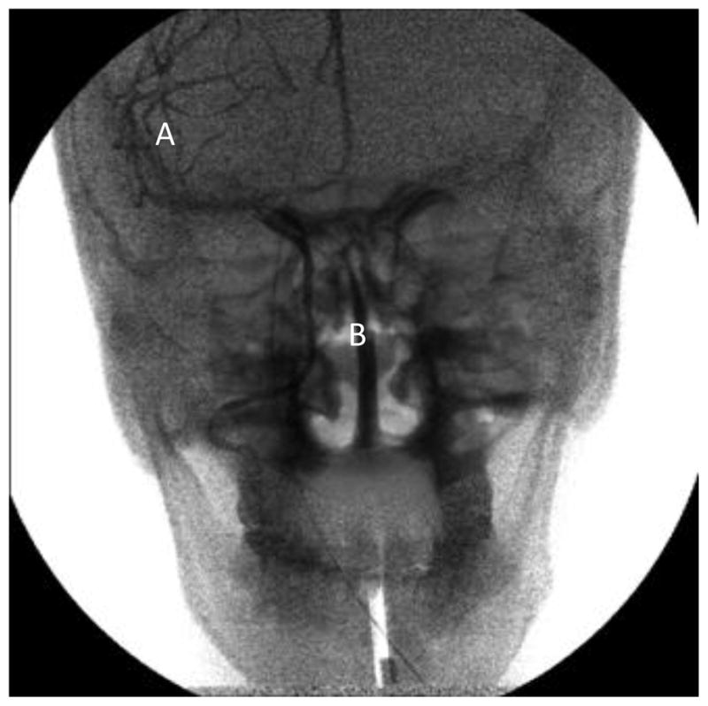
Figure 2.

Input image obtained during ROI fluoroscopy run of head phantom. The x-ray beam modulating attenuator, reduces the number of x-ray quanta incident on it, resulting in an image with differential brightness - region A. Region B is the ROI, with unattenuated quanta incident on the object
Figure 3.
Brightness equalized image during ROI fluoroscopy run. Noise in region A is higher due to fewer quanta
Figure 4.

Higher temporal weight in region A, thus noise reduced, but higher lag. However the guide wire can be seen in both the regions
The equation for a basic temporal recursion filter is given below[3]:
where x(t) is the current input signal at time t (in this case current image), y(t−1) is the previous filtered output, y(t) is the present filter output, α is the filter weight. The output of the filter is the weighted sum of its current input and previous outputs.
A quantitative analysis of signal to noise ratio in comparable regions inside and outside the ROI was presented previously [2] and is repeated here for the convenience of the reader. Two rectangular regions one inside and one outside the ROI were selected (refer to Fig. 5 to see the two rectangular regions). The signal to noise ratio in these two regions is measured after the images are brightness corrected and spatially different temporal filter is applied with different weights inside and outside the ROI. The signal to noise ratio for the region outside the ROI for different temporal weights is presented in table 1.
Figure 5.

Image of the skull phantom used for quantitative analysis. Region A- outside ROI, Region B - inside ROI
Table 1.
Signal to Noise Analysis in similar regions inside and outside the ROI. Different temporal weights, higher weight ouside the ROI and lower weight inside the ROI is applied
| Temporal Weight outside the ROI (α) | SNR(signal to noise) - Outside ROI | SNR(signal to noise)- Inside ROI temporal weight: (α= 0) |
|---|---|---|
| 0 | 2.77 | 5.27 |
| 0.2 | 3.17 | 5.27 |
| 0.39 | 3.71 | 5.27 |
| 0.6 | 4.26 | 5.27 |
| 0.8 | 5 | 5.27 |
In order to evaluate the clinical performance of this technique and simulate live patients, this method was used during two animal studies, one involving a sheep and the other a rabbit. In both the studies, the catheter was guided to the treatment area under ROI fluoroscopy. Real time brightness corrected images were displayed to the interventionalist.
ANIMAL STUDIES
Dose to the patient is reduced by using a beam modulating attenuator. For this study, a stack of Kodak Lanex Regular gadolinium screens with a hole in the middle was used.
In the rabbit studies, the catheter was guided to the aortic arch using the above mentioned technique. The tip of the catheter was placed inside the ROI by the interventionalist and the patient table was moved as the catheter was advanced further towards the heart. Due to added attenuation by the x-ray attenuator, a temporal filter weight of α=0.6 was applied in the region outside the ROI.
Three images from a sequence of 600 images of the above mentioned procedure are shown in figs 6, 7 and 8 from study 1 and figs 9, 10 and 11 from study 2. During the course of study 1 there was a slight movement of the attenuator, causing a boundary artifact during subtraction which can be seen in the image sequence. However this issue was addressed during study 2 as it can be seen from figs 9–11.
Figure 6.

Rabbit study 1, catheter being guided to the region of interest
Figure 7.

Rabbit study 1, descending aorta passing near the diaphragm
Figure 8.

Rabbit study 1, catheter approaching the aortic arch. Although the attenuation outside the ROI is higher as compared to inside the ROI, significant anatomical features of the animal can still be seen, as well as the rest of the catheter
Figure 9.

Rabbit study 2, catheter being guided to the region of interest and the boundary artifact corrected
Figure 10.

Rabbit study 2, descending aorta passing near the diaphragm
Figure 11.

Rabbit study 2, catheter approaching the aortic arch. Although the attenuation outside the ROI is higher as compared to inside the ROI, significant anatomical features of the animal can still be seen, as well as the rest of the catheter.
For a clinical implementation of ROI fluoroscopy a mechanically stable mechanism for inserting the attenuator in the beam would be necessary so as to eliminate this type of asymmetric artifact [4].
In a sheep study, the catheter was guided up the descending aorta of the animal using the dose reduction technique mentioned above. The tip of the catheter was placed inside the region of interest by the interventionalist and the patient table was moved as the catheter was advanced further towards the carotids. Due to added attenuation by x-ray attenuator, a temporal filter weight of 0.8 was applied in the region outside the ROI. The weight inside the ROI was kept very low about 0.1. Six images from a sequence of 400 images of the above mentioned procedure are shown in figs 12–14. The blotchy noise feature seen inside the ROI in figure 12 is due to the anatomy of the sheep. As the catheter is guided further into the animal the noise feature associated with the anatomy changes as can be seen from Figs 13–14.
Figure 12.

Sheep study, distal portion of the descending aorta. The blotchy noise feature in the image is due to the anatomy of the sheep
Figure 14.

Sheep study, catheter guided to the aortic arch, the region of interest.
Figure 13.

Sheep study, entering thoracic portion of the descending aorta
RESULTS AND DISCUSSION
From both the studies it can be seen that despite added attenuation the resulting image with brightness equalized and noise reduced (outside the ROI) can be found to be acceptable to work with. Despite high temporal filtering outside the region of interest, movement of the heart, lung and other major anatomy can still be seen.
For this attenuator stack the ratio of Kerma area Product with and without the material filter was presented previously [2] and was calculated to be 14% thus giving a integral dose reduction of 86%.
A different approach to dose reduction is employed in a technique named SPOT FLUOROSCOPY by Toshiba Medical Systems Corporation [5][6]. This method achieves 100% dose reduction outside the ROI during fluoroscopy by collimating the beam to the required ROI and using a reference fluoroscopy frame in the periphery. However, no real time image information is provided outside the ROI, just a static reference image.
CONCLUSIONS
From these animal studies, it can be concluded that significant dose reduction (of 5–6 times in the attenuating regions) can be achieved with an acceptable image quality in the periphery using the above technique. Even with a higher temporal filter weight outside the ROI, significant anatomical features and movement can still be visualized by the operator.
Acknowledgments
The authors gratefully acknowledge Dr. Hui Meng, Nicholas Liaw and Dr. Daniel D. Swartz for allowing us to use this technique in their animal study. This work was supported in part by NIH Grants R01-EB008425, R01-EB002873 and an equipment grant from Toshiba Medical Systems Corporation.
References
- 1.Rudin S, Bednarek DR, Hoffmann KR. Endovascular image guided interventions (EIGIs) Med Phys. 2008 Jan;35 doi: 10.1118/1.2821702. [DOI] [PMC free article] [PubMed] [Google Scholar]
- 2.Swetadri Vasan SN, Panse A, Jain A, Sharma P, Ciprian, Ionita N, Titus AH, Cartwright AN, Bednarek DR, Rudin S. Dose reduction technique using a combination of a region of interest (ROI) material x-ray attenuator and spatially different temporal filtering for fluoroscopic interventions. Proc SPIE 8313, Medical Imaging 2012: Physics of Medical Imaging. 2012 Feb 23;:831357. doi: 10.1117/12.910945. [DOI] [PMC free article] [PubMed] [Google Scholar]
- 3.Kotre CJ, Guibelalde E. Optimization of variable temporal averaging in digital fluoroscopy. The British Journal of Radiology. 2004;77:675–678. doi: 10.1259/bjr/72726487. [DOI] [PubMed] [Google Scholar]
- 4.Kezerashvili M, Rudin S, Bednarek D. Automatic filter placement device for region of interest (ROI) fluoroscopy. Health Phys. 1997;72(1):141–6. doi: 10.1097/00004032-199701000-00020. [DOI] [PubMed] [Google Scholar]
- 5. [last accessed : Dec 18 2012;]; http://www.medical.toshiba.com.au/xray/index.html.
- 6.Takahashi T, Kurihara T. Diagnostic X-ray System. 7,116,752. U S Patent. 2006 Oct 3;:B2.